City, University of London Institutional Repository
Citation: Marian, Laurentiu (2015). The tuned mass damper inerter for passive vibration
control and energy harvesting in dynamically excited structural systems. (Unpublished Doctoral thesis, City University London)This is the accepted version of the paper.
This version of the publication may differ from the final published
version.
Permanent repository link: http://openaccess.city.ac.uk/14884/
Link to published version:
Copyright and reuse: City Research Online aims to make research
outputs of City, University of London available to a wider audience.
Copyright and Moral Rights remain with the author(s) and/or copyright
holders. URLs from City Research Online may be freely distributed and
linked to.
City Research Online: http://openaccess.city.ac.uk/ publications@city.ac.uk
______________________________________________________________________
______________________________________________________________________
THE TUNED MASS DAMPER INERTER FOR PASSIVE
VIBRATION CONTROL AND ENERGY HARVESTING
IN DYNAMICALLY EXCITED STRUCTURAL SYSTEMS
by
Laurentiu Marian
Dissertation submitted in fulfilment of the requirements for the award of
DOCTOR OF PHILOSOPHY
in
STRUCTURAL ENGINEERING
School of Engineering and Mathematical Sciences
City University London
ii
TABLE OF CONTENTS ... ii
LIST OF TABLES ... vi
LIST OF FIGURES ... viii
ACKNOWLEDGMENTS ...viiiv
DECLARATION ... xv
ABSTRACT……… ... xvi
CHAPTER 1 :INTRODUCTION ... 1
1.1 MOTIVATION AND OBJECTIVES ... 1
1.2 THESIS ORGANISATION AND OUTLINE ... 6
CHAPTER 2 :A REVIEW ON THE CLASSICAL TUNED-MASS-DAMPER AND MASS AMPLIFICATION DEVICES FOCUSING ON APPLICATIONS IN EARTHQUAKE ENGINEERING ... 8
2.1 PASSIVE TUNED-MASS-DAMPER BASED VIBRATION CONTROL ... 8
2.2 THE INERTER AND OTHER MASS AMPLIFICATION DEVICES IN EARTHQUAKE ENGINEERING APPLICATIONS ... 14
CHAPTER 3 :THE TUNED-MASS-DAMPER-INERTER PASSIVE CONTROL SOLUTION FOR SINGLE-DEGREE-OF-FREEDOM PRIMARY SYSTEMS.…………...………..19
iii
3.2 GOVERNING EQUATIONS OF MOTION ... 20
3.3 OPTIMUM DESIGN OF THE TUNED-MASS-DAMPER-INERTER FOR
HARMONIC EXCITATION ... 25
3.3.1 Derivation of closed form solutions for optimum design parameters ... 25
3.3.2 Quantification of the performance enhancement and weight reduction of the Tuned-Mass-Damper-Inerter vis-à-vis the classical Tuned-Mass-Damper... 30
3.4 OPTIMUM DESIGN OF THE TUNED-MASS-DAMPER-INERTER FOR
STOCHASTIC WHITE NOISE EXCITATION ... 36
3.4.1 Derivation of closed form solutions for optimum design parameters ... 36
3.4.2 Quantification of performance enhancement and weight reduction of the Tuned-Mass-Damper-Inerter vis-à-vis the classical Tuned-Mass-Damper. ... 40
CHAPTER 4 :THE TUNED MASS DAMPER – INERTER FOR
SUPPORT-EXCITED MULTI-DEGREE-OF-FREEDOM PRIMARY SYSTEMS ... 45
4.1 PRELIMINARY REMARKS ... 45
4.2 GOVERNING EQUATIONS OF MOTION ... 47
4.3 OPTIMUM DESIGN OF THE TUNED-MASS-DAMPER-INERTER
CONFIGURATION FOR DAMPED MULTI-DEGREE-OF-FREEDOM PRIMARY
SYSTEMS ... 52
4.4 NUMERICAL APPLICATION OF THE TUNED-MASS-DAMPER-INERTER
FOR DAMPED MULTI-DEGREE-OF-FREEDOM PRIMARY SYSTEMS:
OPTIMUM DESIGN FOR STATIONARY COLOURED NOISE SUPPORT
iv
4.4.1 Optimum design of the classical Tuned-Mass-Damper as a special case of the Tuned-Mass-Damper-Inerter configuration ... 57
4.4.2 Optimum design of the Tuned-Mass-Damper-Inerter configuration ... 60
CHAPTER 5:DESIGN AND ASSESMENT OF THE
TUNED-MASS-DAMPER-INERTER FOR SEISMIC PROTECTION OF MULTI-STOREY BUILDINGS . 64
5.1 PRELIMINARY REMARKS ... 64
5.2 EUROCODE 8 COMPATIBLE OPTIMUM
TUNED-MASS-DAMPER-INERTER DEISGN OF BUILDING STRUCTURES ... 68
5.2.1 Optimum Tuned-Mass-Damper-Inerter design parameters ... 71
5.2.2 Top floor displacement variance of optimally designed Tuned-Mass-Damper-Inerter (b>0) versus the Tuned-Mass-Damper (b=0) for Eurocode 8 compatible stochastic excitation. ... 79
5.2.3 On the weight reduction of the Tuned-Mass-Damper Inerter (b>0) versus the classical Tuned-Mass-Damper (b=0) ... 86
5.3 PERFORMANCE ASSESMENT OF OPTIMALLY DESIGNED
TUNED-MASS-DAMPER-INERTER EQUIPPED STRUCTURES USING FIELD
RECORDED EUROCODE 8 COMPATIBLE ACCELEROGRAMS ... 89
5.4 ON THE CONTROL OF HIGHER MODES USING THE
TUNED-MASS-DAMPER-INERTER PASSIVE CONTROL SOLUTION ... 95
CHAPTER 6 :SIMULTANEOUS VIBRATION SUPRESSION AND ENERGY
HARVESTING USING THE TUNED-MASS-DAMPER-INERTER ... 99
v
6.2 MECHANICAL DESCRIPTION AND CHARACTERISATION OF THE
PROPOSED ENERGY HARVESTING ENABLED
TUNED-MASS-DAMPER-INERTER ... 101
6.3 QUANTIFICATION OF ENERGY SCAVENGED BY THE PROPOSED
TUNED-MASS-DAMPER-INERTER ELECTRO-MAGNETIC HARVESTER
DEVICE ... 104
6.4 SIMULTANIOUS ENERGY HARVESTING AND VIBRATION
SUPRESSION FOR TUNED-MASS-DAMPER-INERTER EQUIPPED SYSTEMS
WITH VARYING INERTANCE ... 107
CHAPTER 7 :CONCLUDING REMARKS ... 111
APPENDIX I: ALTERNATIVE CONNECTIVITY ARRANGEMENTS OF
SPRINGS, DAMPERS AND INERTERS ... 120
APPENDIX II : TUNED-MASS-DAMPER-INERTER EQUATIONS OF MOTION
USING A SYSTEM NETWORK APPROACH ... 123
vi
Table 1.1 Matrix of Thesis Contribution ... 5
Table 3.1. Closed-form expressions for optimal TMDI for undamped SDOF harmonically excited primary structures vis-à-vis the classical TMD case ... 29
Table 3.2. Closed-form expressions for optimal tuning of the proposed TMDI configuration for undamped SDOF primary structures subject to white noise base excitation vis-à-vis the classical TMD case. ... 39
Table 4.1 Inertial and elastic properties of the considered 3-DOF primary structure... 56
Table 4.2. Optimal TMDI parameters, Performance Index (PI) and percentage difference of PI achieved for different values of the attached TMDI mass and the inerter constant b compared to the classical TMD (b=0). ... 61
Table 5.1. Inertial and elastic properties of the considered primary structure ... 69
Table 5.2. Undamped natural frequencies of the considered primary structure. ... 69
Table 5.3. Parameters for the definition of C-P evolutionary power spectrum compatible with EC8 spectra ... 71
Table 5.4. The normalized by the top floor value of the first mode shape vector and the corresponding generalised masses ... 72
Table 5.5. TMDI parameters and Performance Index for different values of the additional mTMDI mass and of the inerter constant b. ... 82
Table 5.6. Maximum top floor displacements (cm) for 3DOF Structure IIa ... 90
Table 5.7. Maximum top floor acceleration (g) for 3DOF Structure IIa ... 93
Table 5.8. Maximum mTMDI mass displacements (cm) ... 94
Table 5.9. Inertial and elastic properties of the considered primary structure ... 95
Table 5.10. Undamped natural frequencies of the considered primary structure. ... 95
vii
Table 5.12. Maximum top floor and next-to-top floor displacements (cm) and
accelerations for the 10DOF primary structure ... 98
viii
Figure 2.1 A structural frame model of multi-storey (a) and single-storey (b) building
structures (primary systems) equipped with Tuned-Mass-Damper (TMD) classical
passive control solution ... 9
Figure 2.2 Schematic representation of the two-terminal flywheel device (b is the
mass-equivalent constant of proportionality ... 14
Figure 2.3. Single-degree-of-freedom (SDOF) primary structure ground-connected via an
inerter element. ... 16
Figure 2.4. Possible mechanical realisation of the inerter comprising a plunger that drives
a rotating flywheel through a rack, pinion and gearing system with n gears ... 16
Figure 3.1. Single-degree-of-freedom (SDOF) primary structure equipped with a tuned
mass-damper-inerter (TMDI) system (a) force excited; (b) base-excited. ... 21
Figure 3.2. Single-degree-of-freedom (SDOF) primary structure (modelled as a frame
structure) ground-connected via an inerter element (a) force excited (b) base excited. . 21
Figure 3.3 Relative displacement response amplitude of undamped support excited TMDI
equipped SDOF primary structure with mass ratio μ=0.1, inertance ratio β=0.1, frequency ratio υTMDI=0.5, and for various TMDI damping ratios ζTMDI. ... 26
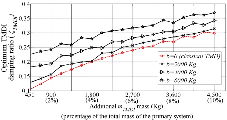
Figure 3.4. Optimum TMDI frequency ratio υTMDI and damping ratio ζTMDI as a function
of the inertance ratio 𝛽 and for several mass ratio values μ. ... 31
Figure 3.5. Dynamic amplification factor spectra for various optimally designed TMDI
(b>0) systems and for the classical TMD (b=0). ... 32
Figure 3.6. Normalized dynamic amplification factor at the “fixed” point ωP1 for
ix
Figure 3.7. Dynamic amplification factor spectra for various optimally designed TMD
(b=0) equipped undamped SDOF systems. ... 34
Figure 3.8. Dynamic amplification factor spectra for various optimally designed TMD
(b=0) equipped undamped SDOF systems. ... 35
Figure 3.9. Optimum TMDI frequency ratio for various values of 𝛽 and several mass
ratio values ... 41
Figure 3.10. Optimum TMD damping ratio for various values of 𝛽 and several mass ratio
values... 41
Figure 3.11. Minimum variance ratio between the proposed model (b>0) and the classical
TMD (b=0) ... 42
Figure 3.12 Additional mTMDI mass values required for achieving the same level of
performance in terms of displacement response variance for the proposes TMDI
configuration and classical TMD (b=0) ... 44
Figure 4.1. Multi-degree-of-freedom (MDOF) primary structure incorporating the
proposed tuned mass-damper-inerter (TMDI) configuration. ... 46
Figure 4.2. One-sided power spectrum representing the acceleration support excitation
αg(t)... 57
Figure 4.3. Optimum frequency ratio as a function of the TMD mass for various values
of the inerter constant b to control the fundamental mode of vibration of the 3-DOF primary structure of Table 4.1 ... 58
Figure 4.4. Optimum damping ratio as a function of the TMD mass for various values of
the inerter constant b to control the fundamental mode of vibration of the 3-DOF primary structure of Table 4.1. ... 58
Figure 4.5. Achieved performance index versus the TMD mass for various values of the
x
Figure 5.1. Tuned mass-damper-inerter (TMDI) equipped n-storey frame building. ... 66 Figure 5.2. Considered EC8 compatible evolutionary power spectrum S(ω,t) for design purposes ... 70
Figure 5.3. Three DOF primary structure (I). Optimum TMDI parameters. Frequency
ratio (a) and TMDI damping ratio (b), versus the additional mTMDI mass for various values
of b. ... 73 Figure 5.4. Three DOF primary structure (IIa). Optimum TMDI parameters. Frequency
ratio (a) and TMDI damping ratio (b), versus the additional mTMDI mass for various values
of b. ... 74 Figure 5.5. Three DOF primary structure (IIIa). Optimum TMDI parameters. Frequency
ratio (a) and TMDI damping ratio (b), versus the additional mTMDI mass for various
values of b. ... 74
Figure 5.6. Three DOF primary structure (I). Optimum TMDI parameters. TMDI stiffnes
value (a) and TMDI damping value (b), versus the additional mTMDI mass for various
values of b. ... 75 Figure 5.7. Three DOF primary structure (IIa). Optimum TMDI parameters. TMDI
stiffnes value (a) and TMDI damping value (b), versus the additional mTMDI mass for
various values of b. ... 76 Figure 5.8. Three DOF primary structure (IIIa). Optimum TMDI parameters. TMDI
stiffnes value (a) and TMDI damping value (b), versus the additional mTMDI mass for
various values of b. ... 77 Figure 5.9. Optimum TMDI parameters. Comparison of TMDI stiffness value versus the
additional mTMDI mass for all primary structures considered. ... 78
Figure 5.10. Optimum TMDI parameters. Comparison of TMDI damping value versus
xi
Figure 5.11. Three DOF primary structure - 3DOF (I). Performance index versus the
additional mTMDI mass for various values of b. ... 79
Figure 5.12. Three DOF primary structure - 3DOF (IIa). Performance index versus the
additional mTMDI mass for various values of b. ... 80
Figure 5.13. Three DOF primary structure - 3DOF (IIb). Performance index versus the
additional mTMDI mass for various values of b. ... 80
Figure 5.14. Three DOF primary structure - 3DOF (IIIa). Performance index versus the
additional mTMDI mass for various values of b. ... 81
Figure 5.15. Three DOF primary structure - 3DOF (IIIb). Performance index versus the
additional mTMDI mass for various values of b. ... 81
Figure 5.16. Performance index ratio between an optimum designed TMD and an
optimum designed TMDI for an mTMDI mass of 10% from the total mass of the primary
structure and for various values of b. ... 84 Figure 5.17. Three DOF primary structure - 3DOF (IIa). Performance index versus the
additional mTMDI mass for various values of b. Robustness assessment of optimal TMDI
on structures with uncertainty in natural frequency. ... 85
Figure 5.18. Absolute transfer function between the input ground acceleration and the
output top floor displacement for the uncontrolled (primary) structure 3DOF IIa, structure
equipped with optimal TMD and structure equipped with optimal TMDI ... 86
Figure 5.19. Additional mTMDI mass values required for achieving the same level of
performance index for the proposed TMDI configuration (b>0) and for classical TMD
(b=0). Three DOF primary structure - 3DOF (I). ... 87
Figure 5.20. Additional mTMDI mass values required for achieving the same level of
performance index for the proposed TMDI configuration (b>0) and for classical TMD
xii
Figure 5.21. Additional mTMDI mass values required for achieving the same level of
performance index for the proposed TMDI configuration (b>0) and for classical TMD
(b=0). Three DOF primary structure - 3DOF (IIIa). ... 88
Figure 5.22. Response spectra of the considered EC8 compatible field recorded
accelerograms listed in Table 5.6 ... 90
Figure 5.23. Three DOF primary structure IIa. Top floor displacement responses for
uncontrolled structure, structure equipped with optimal TMD and structure equipped with
optimal TMD and TTF device. ... 91
Figure 5.24. Three DOF primary structure IIa. Top floor acceleration responses for
uncontrolled structure, structure equipped with optimal TMD and structure equipped with
optimal TMD and TTF device. ... 92
Figure 5.25. Absolute transfer function between the input ground acceleration and the
output top floor displacement for the 10DOF uncontrolled (primary) structure, structure
equipped with optimal TMD and structure equipped with optimal TMDI ... 96
Figure 5.26. Absolute transfer function between the input ground acceleration and the
output top floor acceleration for the regular 10DOF uncontrolled (primary) structure,
structure equipped with optimal TMD and structure equipped with optimal TMDI ... 97
Figure 6.1 Single-degree-of-freedom (SDOF) primary structure incorporating the
proposed tuned mass-damper-inerter-harvester (TMDI-H) configuration. ... 102
Figure 6.2. Normalized relative velocity amplitude for an undamped structure equipped
with optimal TMDI configuration ... 105
Figure 6.3. Normalized power harvested from various TMDI systems optimally designed
xiii
Figure 6.4. Dynamic amplification factor spectra (left panel) for an optimally designed
TMDI system for vibration suppresion with µ=0.1and 𝛽=0.6 (fixed ʋTMDI=0.5651 and
ζTMDI=0.4132)and for several values of inertance. ... 108
Figure 6.5. Normalized power harvested speactra for an optimally designed TMDI system
for vibration suppresion with µ=0.1and 𝛽=0.6 (fixed ʋTMDI=0.5651 and ζTMDI=0.4132)
and for several values of inertance. ... 108
Figure 6.6. Peak dynamic amplification factor for the non-optimal TMDI configurations normalized by the maximum of the dynamic amplification factor for optimally designed
TMDI (for β=0.6) as functions of the inertance ratio β ... 109 Figure 6.7. Peak normalized potential harvesting power for the non-optimal TMDI configurations normalized by the maximum of the dynamic amplification factor for
optimally designed TMDI (for β=0.6) as functions of the inertance ratio β... 110 Figure 0.1. Alternative connectivity arrangements of TMD-inerter considered ... 120
Figure 0.2. Dynamic amplification factor for the system equipped with TMD and for the
xiv
First and foremost, I would like to express my sincere gratitude to my supervisor,
Dr Agathoklis Giaralis for his invaluable continuous support, advice and guidance. He is
indeed the most rigorous, supportive and dedicated supervisor anyone would hope to have
and has been an inspiration throughout my research work and our close collaboration.
Further, the financial support provided by City University London is gratefully
acknowledged.
A heartfelt thanks to all my former research colleges at City University for their
support and friendship.
In addition, I would also like to express my appreciation to my family’s
unconditional love. This work would not have been possible without their support and
understanding.
xv
I grant powers of discretion to the University Librarian to allow this dissertation to be
copied in whole or in part without further reference to me. This permission covers only
single copies made for study purposes, subject to normal conditions of
xvi
A novel passive vibration control configuration, namely the Tuned-Mass-Damper-Inerter (TMDI) is proposed in this work. The TMDI combines the “inerter”, a mechanical two-terminal flywheel device developing resisting forces proportional to the relative acceleration of its terminals, with the well-known and widely used in various passive vibration control applications Tuned-Mass-damper (TMD). Introduced as a generalization of the TMD, the TMDI takes advantage of the “mass amplification effect” of the inerter to achieve enhanced performance compared to the classical TMD. For linear harmonically excited primary systems, analytical closed-form expressions are derived for optimal TMDI design/tuning parameters using the well-established and widely applied for the case of the classical TMD semi-empirical fixed-point theory. It is shown that for the same attached mass the TMDI system is more effective than the classical TMD to suppress vibrations close to the natural frequency of the uncontrolled primary system, while it is more robust to de-tuning effects. Moreover, it is analytically shown that optimally designed TMDI outperforms the classical TMD in minimizing the displacement variance of undamped linear single-degree-of-freedom (SDOF) white-noise excited primary systems. For this particular case, optimal TMDI parameters are derived in closed-form as functions of the additional oscillating mass and the inerter constant.
Furthermore, pertinent numerical data are furnished, derived by means of a numerical optimization procedure, for classically damped mechanical cascaded chain-like primary systems base excited by stationary colored noise. This exemplifies the effectiveness of the TMDI over the classical TMD to suppress the fundamental mode of vibration for linear MDOF structures. It is concluded that the incorporation of the inerter in the proposed TMDI configuration can either replace part of the TMD vibrating mass to achieve lightweight passive vibration control solutions, or improve the performance of the classical TMD for a given TMD mass.
The TMDI is further applied for passive vibration control of seismically excited building structures. An input non-stationary stochastic process compatible with the elastic design spectrum of the European aseismic code provisions (EC8) is assumed. The effectiveness of the proposed TMDI configuration over the classical TMD is assessed by performing response history analyses for an ensemble of EC8 spectrum compatible field recorded strong ground motions. The optimally tuned TMDI solution achieves considerable reduction of the peak average top floor displacement and peak average top floor accelerations of the considered primary structures compared to the one achieved by the optimally designed classical TMD, assuming the same additional mass in both cases. Furthermore, the TMDI configuration achieves significant reduction in the maximum displacement of the additional oscillating mass. In this study, the primary structures are assumed to behave linearly in alignment with current trends in performance based requirements for minimally damaged structures protected by passive control devices.
Furthermore, optimally designed TMDI is applied for vibration suppression and energy harvesting via an electromagnetic device which transforms the mechanical kinetic
xvii
energy into electrical energy. Unlike the case of traditional energy harvesting enabled TMD systems, the amount of available energy to be harvested by the herein proposed TMDI-based harvester is leveraged by changing the intensity of the mass amplification effect of the inerter, through mechanical gearing, without changing the weight of the TMDI system. Therefore, the inclusion of the inerter adds a “degree of freedom” or a design parameter to the classical TMD-based harvesters allowing to control the trade-off between vibration suppression and energy harvesting in a more flexible manner.
______________________________________________________________________
______________________________________________________________________
1.1
MOTIVATION AND OBJECTIVES
Depending on their location certain civil structured facilities can be subjected to
dynamic loads due to gusty wind fronts and/or strong ground motion associated with
earthquake events of different intensity/severity during their life service. At high levels
of intensity these naturally occurring dynamic loads may induce permanent structural
damage and, in extreme cases, total structural failure/collapse. During the past three
decades the incorporation of various devices such as base isolators, energy dissipation
equipment (e.g. viscous dampers, friction dampers, etc.), and tuned-mass dampers
(TMDs) has been considered by various researchers and has been applied in practice to
passively control the vibratory motion of structures maintaining its amplitude below
certain acceptable thresholds (Martelli & Forni, 2011; Spencer Jr, 2002; Soong &
Dargush, 1999; Chang, 1999). Typically, such “non-conventional” means of mitigating
the hazard posed to structures due to the action of winds and earthquakes are applied to
protect critical civil infrastructure such as high-rise buildings, hospitals, and long-span
(foot)bridges. Furthermore, the employment of such passive devices is commonly
considered to upgrade/reinforce existing/historical structures to meet the contemporary
safety criteria and to retrofit damaged structures in the aftermath of severe seismic events.
These practical applications have sustained the important and active research field of
passive vibration control for new and for existing/damaged structures. Admittedly, it is
noted that improved structural performance can be achieved by using active/semi-active
control solutions relying on the integration of sensors, controllers and real-time data
2
processing (Spencer & Nagarajaiah, 2003; Yoshioka et al, 2002; Ozbulut et al, 2011).
However, due to reliability issues and the installation cost of such solutions, the use of
active control systems is not as wide spread as the passive control solutions.
In the context of passive vibration control, the concept of the dynamic vibration
absorber is historically one of the first and most widely used strategies for passive
vibration mitigation of dynamically excited mechanical and civil engineering structures
and structural components (Frahm, 1911 and Ormondroyd & Den Hartog, 1928). It relies
on attaching an additional free-to-vibrate mass to the structural system (primary or host
structure) whose motion is to be suppressed via certain mechanical devices. These devices
are appropriately designed (or “tuned”) such that a resonant out-of-phase motion of the
attached mass is achieved compared to the primary structure. Arguably, the most
commonly used dynamic vibration absorber is the so-called “tuned mass-damper”
(TMD). In its simplest form, the TMD considers a linear spring and a viscous damper to
link the additional mass to the primary structure. The effectiveness of this classical TMD
relies on tuning its stiffness and damping properties such that significant kinetic energy
is transferred from the vibrating primary structure to the TMD mass and is absorbed
through the viscous damper.
Despite being widely used due to the relatively simple and well-established design
procedures, the TMD suffers the problem of “detuning” (e.g. due to non-linear response
or a change in the dynamic properties of the primary structure) which may significantly
affect its vibration suppression performance especially for the case of narrow band or
harmonic excitations. Moreover, the TMD is not robust to uncertainties in estimating the
properties of the primary structure from which the optimal TMD design parameters
depend on. To address these issues, various different strategies have been employed such
3
dampers in place of the linear dashpot (e.g. Ricciardelli & Vickery, 1999). These
strategies do offer enhanced performance compared to the classical TMD, however, they
add a further layer of complexity; optimum design/tuning becomes a challenging and
computationally involved task. In this regard, it should be noted that, perhaps, the most
straightforward way to enhance the performance and robustness of the TMD is to increase
the attached mass for which optimum TMD design is sought. Indeed, the larger the
attached mass considered, the more effective an optimally designed TMD becomes to
suppress excessive primary structure vibrations at the cost of an increase total weight of
the structural system (see e.g. Angelis et al, 2012; Hoang et al, 2008 and references
therein).
Motivated by the latter observations, this thesis considers the addition of a mass
amplification mechanical device, dubbed the “inerter” by Smith (2002), to enhance the
performance of the classical TMD configuration. The thus proposed
Tuned-Mass-Damper Inerter (TMDI) exploits the apparent mass amplification effect of the inerter, a
two-terminal device developing a resisting force proportional to the relative acceleration
of its terminals, to achieve improved vibration control compared to the TMD for the same
attached mass.
In this context, the underlying equations of motion for linear SDOF and MDOF
TMDI equipped primary structures are first introduced in the thesis. It is shown that the
TMDI constitutes a generalization of the classical TMD. Next, standard optimisation
techniques used for the classical TMD are applied to derive optimum TMDI parameters.
Focus is given to the vibration control performance of the TMDI over the one achieved
by the TMD. In particular, a significant part of this thesis is focused on deriving analytical
closed-form expressions for optimal TMDI design/tuning parameters for harmonically
4
For multi-degree-of freedom (MDOF) cascaded chain-like mechanical systems,
pertinent numerical data are furnished, derived by means of a numerical optimization
procedure when considering stationary “coloured noise” base excitation.
Next, the TMDI is utilized to achieve a lightweight passive vibration solution for
seismically excited building structures, focusing as well on the reduction of the peak
average top floor displacements/accelerations and on the reduction of the required
additional oscillating mass stroke. For this purpose, an input non-stationary stochastic
process compatible with the elastic design spectrum of the European aseismic code
provisions (EC8) is assumed. Furthermore, the effectiveness of the proposed optimum
designed TMDI configuration over the classical TMD is assessed through response
history analyses for an ensemble of 7 EC8 spectrum compatible field recorded strong
ground motions.
Further, optimally designed TMDIs are applied for simultaneous vibration control
and energy harvesting .The latter study is motivated by the fact that in considering a
passive TMD-based harvester device, as the oscillating TMD mass increases, better
primary structure response reduction is achieved but at the cost of reduced available
energy for harvesting (Gonzalez-Buelga et al, 2014; Tang & Zuo, 2012; Adhikari & Ali,
2013).
In view of the above, Table 1.1 summarises for clarity the main contribution of
this thesis within a matrix format. Furthermore, the same table provides a location map
of each TMDI development/application within the thesis’s chapters. Several publications
5 Table 1.1 Matrix of Thesis Contribution
TYPE OF PRIMARY SYSTEMS CONSIDERED
Single Degree of Freedom Primary
System
Multi Degree of Freedom Primary Systems
DEVELOPMENT OF THE TMDI
Governing
equations of
motion
- In time and frequency
domain. (2) (3)
(Chapter 2)
- In time and frequency domain. (1)
-State Space Formulation.
-Admittance Matrix Formulation (1)
(Chapter 4), (Appendix II)
Optimum
design
- Closed form Expression
for Undamped primary
systems.(3)
(Chapter 3)
- Numerical Optimisation –
“min-max” constraint optimization
algorithm employing a sequential
programming method. (1), (2)
(Chapter 4 & Chapter 5)
APPLICATIONS
Simultaneous vibration
suppression and energy
harvesting. (3)
(Chapter 6)
- Earthquake protection for
multi-storey buildings.(1)
(Chapter 5)
(1) Marian, L. & Giaralis, A. 2013. Optimal design of inerter devices combined with TMDs for vibration
control of buildings exposed to stochastic seismic excitations. In: Proceedings of the 11th ICOSSAR
International Conference on Structural Safety and Reliability for Integrating Structural Analysis, Risk and
Reliability; New York, US (eds: Deodatis G, Ellingwood BR and Frangopol DM), CRC Press.
(2)Marian, L. & Giaralis, A. 2014. Optimal design of a novel tuned mass-damper-inerter (TMDI) passive
vibration control configuration for stochastically support-excited structural systems. Probabilistic
Engineering Mechanics 2014; DOI:/10.1016/j.probengmech.2014.03.007.
(3) Marian, L. & Giaralis, A. 2014. Vibration suppression and energy harvesting in tuned mass-damper –
inerter (TMDI) equipped harmonically support-excited structures. In: Proceedings of the 6thInternational
6
1.2
THESIS ORGANISATION AND OUTLINE
This dissertation comprises seven chapters and one appendix followed by the list
of cited references. The introductory first chapter presents the motivation and the objectives
of the undertaken work. It outlines the chapters within the thesis with a short summary of
their content.
Chapter 2 provides a brief review on the classical tuned-mass-damper (TMD) and
on the inerter, focusing on applications in structural engineering.
In Chapter 3 the governing equations of motion and relevant transfer functions of
the proposed tuned-mass-damper-inerter (TMDI) configuration are derived for the case
of linear single-degree-of-freedom (SDOF) primary systems. Analytical expressions are
derived in closed form for optimum TMDI parameters minimizing the displacement
amplitude response for the special case of undamped harmonically base-excited SDOF
primary systems. Furthermore, analytical expressions for optimum TMDI parameters
minimizing the displacement variance for the special case of undamped white noise
excited SDOF primary systems are obtained.
Chapter 4 introduces the TMDI configuration to suppress oscillations following
the fundamental mode of vibration of support-excited damped multi-degree-of-freedom
(MDOF) chain-like primary systems. A numerical optimization procedure for optimum
design of the TMDI for these primary systems is also discussed. Numerical data is
provided to demonstrate the effectiveness and applicability of the TMDI vis-à-vis the
classical TMD for classically damped support excited MDOF chain-like primary systems.
Chapter 5 applies the TMDI system to achieve a lightweight passive vibration
solution for seismically excited building structures. For optimum TMDI parameters
7
spectrum of the current European aseismic code provisions (EC8) is considered.
Moreover, the effectiveness of the proposed TMDI configuration over the classical TMD
is assessed by performing response history analyses for an ensemble of Eurocode 8
spectrum compatible field recorded strong ground motions.
In Chapter 6 the TMDI is applied for simultaneous vibration suppression and
energy harvesting. Analytical and numerical results are reported on the capabilities of
optimally designed TMDIs for vibration suppression to harvest energy by transferring the
kinetic energy from harmonically base excited SDOF primary structures into electrical
energy via a particular electromagnetic energy harvester.
8
2.1
PASSIVE TUNED MASS DAMPER BASED VIBRATION
CONTROL
The idea of attaching an additional free-to-vibrate mass to dynamically excited
structural systems (primary structures) to suppress their oscillatory motion is historically
among the first passive vibration control strategies in the area of structural dynamics
(Frahm, 1911; Ormondroyd & Den Hartog, 1928; Den Hartog, 1956; Brock, 1946). This
idea relies on designing or “tuning” the mechanical devices that link the added mass to
the primary structure to achieve a “resonant” out-of-phase motion of the mass. In this
context, (Frahm, 1911) introduced the use of a linear spring-mass attachment to suppress
the oscillations of harmonically excited primary structural systems in naval and
mechanical engineering applications. This early “dynamic vibration absorber” was able
to reduce the oscillations of single-degree-of-freedom (SDOF) primary structures within
a narrow range centred at a particular (pre-specified) frequency of excitation. Later,
Ormondroyd and Den Hartog (1928) enhanced the effectiveness of the above absorber to
dissipate the kinetic energy of primary structures by appending a viscous damper
(dashpot) in parallel to the linear spring. This is known as the Tuned Mass Damper (TMD)
shown in Figure 2.1 for single-degree-of-freedom (SDOF) and multi-degree-of-freedom
(MDOF) primary structures.
CHAPTER 2 :
A REVIEW ON THE CLASSICAL TUNED MASS
DAMPER (TMD) AND MASS AMPLIFICATION DEVICES
FOCUSING
ON
APPLICATIONS
IN
EARTHQUAKE
9
[image:27.595.161.495.74.296.2]
Figure 2.1 A structural frame model of multi-storey (a) and single-storey (b) building structures (primary
systems) equipped with Tuned-Mass-Damper (TMD) classical passive control solution
A semi-empirical “optimum” design procedure has been established by Den
Hartog (Den Hartog, 1956) and Brock (Brock, 1946) to “tune” the damping and stiffness
properties for an a priori specified mass of this spring-mass-damper attachment such that the peak displacement of harmonically excited undamped SDOF primary structures is
minimized (see Krenk, 2005). This design/tuning procedure relies on the “fixed point”
assumption which states that all frequency response curves of the resulting two-DOF
dynamical system pass through two specific points; the location of these points being
independent of the damping coefficient of the dashpot. Thus the tuned spring-mass-
damper attachment, commonly termed in the literature as the “tuned mass-damper”
(TMD), achieves the suppression of the oscillatory motion of harmonically excited
primary structures over a wider range of exciting frequencies compared to a spring-mass
attachment. Recently, the fixed point-based tuning procedure was shown to be very close
to the “exact” solution for the optimal tuning of the classical TMD (Nishihara & Asami,
10
does not strictly hold and the derivation of optimal TMD parameters in closed form
becomes a challenging task (e.g. Nishihara & Asami, 2002; Asami et al, 2002). In this
respect, numerical optimization techniques are applied in practice for optimal design of
TMDs (e.g. Leung & Zhang, 2009). Motivated mostly by earthquake engineering
applications, Warburton (1982) derived optimum TMD parameters based on the fixed
point theory for the case of harmonically base excited undamped SDOF structures.
Further, substantial research work has been devoted to investigate the potential of using
the classical TMD to mitigate the motion of stochastically support-excited primary
structures. Using standard analytical techniques, optimal TMD parameters can be readily
obtained in closed-form as functions of the TMD mass to minimise the response variance
of undamped SDOF primary structures subject to white noise support excitation
(Ayorinde & Warburton, 1980; Warburton, 1982). However, for the case of damped
SDOF primary structures subjected to stochastic support excitations, the derivation of
optimal TMD parameters by analytical approaches becomes a challenging task. To this
end, numerical optimization techniques are commonly employed for optimum design of
TMDs to minimize the response variance for such primary structures (see e.g. Bakre &
Jangid, 2005; Hoang et al, 2008; Leung & Zhang, 2009; Salvi & Rizzi, 2011).
Alternatively, simplified approximate solutions for the problem at hand have been
reached by making the assumption of “lightly” damped primary structures (e.g. Ghosh &
Basu, 2005; Krenk & Høgsberg, 2008). Along similar lines, several researchers proposed
different approximate simplified and numerical methods for the design of TMDs for
damped linear multi-degree-of-freedom (MDOF) primary structures under stochastic
base excitation widely used to model seismically excited multi-storey building structures
(see e.g. Sadek et al, 1997, Rana & Soong, 1998, Moutinho, 2012, Angelis et al, 2012 and
11
multi degree-of-freedom (MDOF) primary structures is a straightforward task since, in
common practice, the aim is to control vibrations according to a single (the dominant)
structural mode shape (e.g. Rana & Soong, 1998).
Although alternative arrangements of linear springs and dashpots (viscous
dampers) have been considered in the literature to attach a mass to primary structures (see
e.g. Liu & Liu, 2005, Cheung & Wong, 2011 and references therein), the above discussed
“classical” TMD configuration (mass attached via a spring and a dashpot in parallel) is
the most widely studied in the literature and the most commonly used one for passive
vibration control of various mechanical and civil engineering structures and structural
components.
In recent years, several different strategies have been employed to enhance the
performance of the classical TMD for passive vibration suppression of structural systems
including the use of multiple classical TMDs (see e.g. Hoang & Warnitchai, 2005; Lee et
al, 2006 and references therein), the incorporation of non-linear viscous dampers to the
classical TMD configuration (Rudinger, 2006), and the consideration of hysteretic TMDs
(see e.g. Ricciardelli & Vickery, 1999). These strategies do offer enhanced performance
compared to the classical TMD, however, optimum design/tuning becomes a challenging
and computationally involved task, especially for damped MDOF primary structures.
Furthermore, analytical and numerical results reported in the extensive relevant literature
suggest that the effectiveness of the TMD for vibration mitigation of base-excited
structures increases by increasing the attached TMD mass. This is particularly the case
for high intensity support excitations (e.g. Hoang et al, 2008; Angelis et al, 2012).
Indeed, the larger the attached mass considered, the more effective an optimally
designed TMD becomes to suppress excessive primary structure vibrations at the cost of
12
recent studies focus towards non-conventional configurations which have in common the
employment of significantly large TMD masses, which can reach the order of 15% to
100% of the primary structure total mass (Feng & Mita, 1995; Moutinho, 2012; Angelis
et al, 2012; Hoang et al, 2008; Matta & DeStefano, 2009a; 2009b). This can be
accomplished by the use of substructures utilized as self-contained vibration absorbers in
tall buildings, as proposed by Feng & Mita (1995) where it is shown that the use of this
‘mega-substructure configuration’ with masses that can reach 100% of the mass of the
structure’s main body significantly improves the seismic response of primary structures.
Moreover, in (Moutinho, 2012) it is proposed to use the top floor of a five storey shear
building as a large mass TMD to reduce induced seismic vibrations, assuming TMD
masses which can reach the total mass of the primary structure. This is accomplished
through the use of rubber bearings which are interposed between the top of the columns
on the last floor and the roof. It is proven that the use of large mass TMDs improves
robustness in terms of parameter uncertainties. In a similar manner, large TMDs are also
proposed in (Angelis et al, 2012) with masses equal to72% of the primary system’s mass.
The study is carried out by means of both numerical analyses and experimental tests. It is
concluded that large mass TMDs lead to greater reductions of the structural response
compared to conventional ones. The proposed solution is also found to be more robust
against deviations of optimum parameters resulting from uncertainties in structural
properties. Large mass TMDs are also employed in Hoang et al (2008) for the case of a
SDOF structure on a design example for seismic retrofitting of a long-span truss bridge.
A TMD mass equal to 77% of the total mass of the primary structure is proposed. Its
performance is proved to be robust with respect to uncertainties in the system structural
parameters as well as the excitation frequency content. Furthermore, the concept of the
13
(2009) where non-structural large masses already available atop buildings are turned into
TMDs. The occurring TMD mass-uncertainties are inspected through a robust analysis.
The same authors (Matta & DeStefano, 2009b) provide a comparison between the
previously proposed rolling-pendulum and the classical translational TMD configuration.
Given that large mass TMD lead to an undesirable increase of the weight which
needs to be accommodated by the primary structure using structurally sophisticated
solutions, there is scope in seeking ways to reduce the attached TMD mass to facilitate
practical structural design, while maintaining the well-documented effectiveness of large
mass TMDs to mitigate seismic risk associated with moderate-to-severe earthquake
induced ground shaking. In this regard, in this thesis the classical TMD is coupled with
mass amplification devices, reviewed in the following section, aiming to achieve
14
2.2
THE INERTER AND OTHER MASS AMPLIFICATION
DEVICES IN EARTHQUAKE ENGINEERING APPLICATIONS
Conceptually introduced by Smith (2002), the ideal inerter is a two terminal
mechanical element of negligible mass/weight developing an internal (resisting) force
proportional to the relative acceleration of its terminals which are free to move
independently. Figure 2.2 depicts an inerter device whose terminals are subject to an equal
and opposite externally applied force F in equilibrium with the internally developed force. By definition the following relationship holds for the ideal linear inerter (e.g. Smith, 2002;
Chuan et al, 2011a):
1 2
( -
)
F
b u u
, (2-1)where u1 and u2 are the displacement coordinates of the two terminals and a dot over
[image:32.595.274.377.569.615.2]symbol signifies differentiation with respect to time t. In the above equation, the constant of proportionality b attains mass units and fully characterizes the behaviour of the inerter. Still, the physical mass of an actual inerter device is orders of magnitude lower than b.
Figure 2.2 Schematic representation of the two-terminal flywheel device (b is the mass-equivalent
constant of proportionality
Employing rack and pinion gearing arrangements or ball screw mechanisms to drive
a rotating flywheel several such devices have been built and prototyped (Smith, 2002;
15
successfully used for vibration control of suspension systems in high performance
vehicles (e.g. Evangelou et al, 2004; Chuan et al, 2011b and others). More, recently, fluid
inerter implementations have been proposed (Swift et al, 2013; Wang et al, 2011) which
use the mass of a fluid flowing through a helical channel to generate the required resistive
force. Inerter devices can be viewed and modelled as a linear mechanical element which
complements the ideal linear spring element (i.e. two-terminal device developing an
internal force proportional to the relative displacement of its terminals) and the linear
dashpot (i.e. two-terminal device developing an internal force proportional to the relative
velocity of its terminals). To this end, the concept of the inerter allows for a one-to-one
mapping of dynamical mechanical systems for passive vibration control analogously to
the electrical network synthesis. In fact, the concept of the inerter allows for designing
mechanical systems for passive vibration control analogously to the electrical network
synthesis. To this end, various topologies of springs, dampers, and inerters have been
tested for vibration isolation of vehicles. (Chuan et al, 2011b, Evangelou et al, 2004)
Of particular importance for the purpose of this thesis is the mass amplification
effect of the inerter which has been noted in the original paper of Smith (2002). This
effect can be readily understood by examining a seismically excited linear
spring-inerter-mass system. Specifically, consider the single storey portal frame building of Figure 2.3
having an inerter device exposed to a horizontal seismic excitation and modelled as a
linear single-degree-of-freedom system with k1 lateral stiffness, m1 mass assumed to be
lumped at the girder. Let the girder be connected to the ground by means of an ideal
inerter device. The equation of motion of this structure written in terms of the horizontal
floor displacement relative to the ground motion is given as:
16
Figure 2.3. Single-degree-of-freedom (SDOF) primary structure ground-connected via an inerter element.
Clearly, the inclusion of the inerter increases the “apparent” mass of the portal
frame by b. However, the physical mass of the inerter is assumed to be negligible compared to the mass m1, in accordance with the definition of the concept of the inerter
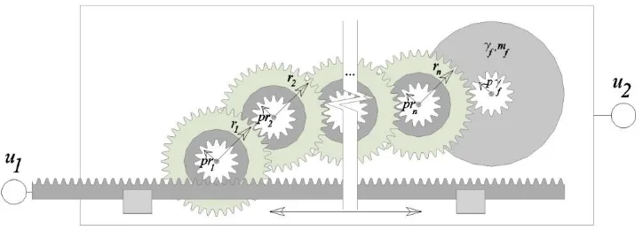
as defined in Smith (2002). To further elaborate on this matter, Figure 2.4 provides a
mechanical realisation of the inerter comprising a plunger that drives a rotating flywheel
through a rack, pinion, and a gearing system with n gears (e.g. Smith, 2002).
Figure 2.4. Possible mechanical realisation of the inerter comprising a plunger that drives a rotating
[image:34.595.126.488.483.613.2]17
The inertance b achieved from such a mechanical device is expressed as:
2 2
2 2
1
( )
n
f i
f i pr i
r
b m
pr
(2-3)
where mf is the mass of the flywheel and γf is the radius of gyration of the flywheel; rf
represents the radius of the flywheel pinion and n represents the number of gears with radius ri and pinion radius rj chained together between the input gear and the output
flywheel pinion. It can be easily deducted from Equation (2-3) that, as the number of
gears considered in the mechanical realization of the inerter increases, the inertance b and implicitly the mass amplification effect increases proportional.
Importantly, the inclusion of the inerter changes (reduces) the natural frequency of
the system. This issue has been recently examined in (Chen et al, 2014). Further, the
amplitude of the effective horizontal force is also reduced, consideration which has been
extensively discussed in (Takewaki et al 2012).
The use of mass amplification devices/inerters for vibration mitigation in
seismically excited buildings has recently attracted some attention in the literature. Wang
et al. (2007; 2010) propose various passive vibration control configurations, assessing the
performance of several suspension layouts employing inerters placed in between the
ground and the superstructure in a base isolation type of arrangement. It has been
established that inerter devices are effective in controlling the response of rigid
superstructures exposed to vertical band-limited white noise ground motions. Passive
vibration control systems comprising inerters in conjunction with springs and dampers
have been considered by Lazar et al. (2013a; 2013b) for vibration isolation of primary
systems subjected to recorded earthquake excitations applied along the vertical direction.
18
amplifier”, which achieves a similar dynamic effect as the inerter, in parallel with a
viscous damper have been discussed in the literature (e.g. Hwang et al, 2007; Ikago et al,
2012 and others). These rotational inertia dampers are usually arranged as diagonal
bracing members in multi-story framed buildings to provide supplemental damping and
inertia properties to structures (e.g. Ikago et al, 2012). In this manner, passive control of
seismically excited buildings is achieved by increase of the inherent to all structures
damping and mass properties. Furthermore, a new vibration control device is proposed in
(Garrido et al, 2013) called rotational inertia double-tuned mass damper (RIDTMD),
consisting of a classical TMD and a rotational inertia element similar to the inerter. The
efficiency of the proposed configurations vis-à-vis the classical TMD is assessed via a
numerical optimisation for SDOF primary structures subjected to harmonic load. In
(Takewaki et al, 2012) it is shown that inerters distributed along the height of a
seismically excited structure are effective for the reduction of the maximum absolute
horizontal acceleration of floors by reducing the applied to the structure horizontal load.
It is noted that, the TMDI discussed in the following chapters is significantly
different than the TDI in (Lazar et al., 2013) and the solutions of (Ikago et al, 2012) as in
all these cases the inerter is placed as a strut within the storeys of buildings in combination
with spring and damping elements. Further, in a similar manner, Takewaki uses inerters
19
3.1
PRELIMINARY REMARKS
This chapter introduces the Tuned Mass Damper-Inerter (TMDI) for vibration
control of harmonically and stochastically excited single-degree-of-freedom (SDOF)
primary systems. The herein proposed TMDI configuration takes advantage of the “mass
amplification effect” of the inerter by using it as an additional connective element
between the TMD oscillating mass and the ground for SDOF primary systems.
Importantly, the TMDI can be viewed as a generalization of the classical TMD. Thus, all
established in the literature procedures for optimum design (tuning) of the classical TMD
are readily applicable to achieve optimal performance for the TMDI configuration.
In addition to the herein considered TMDI configuration, several other
spring-mass-damper and inerter connectivity arrangements have been studied, as exemplified in
Appendix I. However, as detailed in Chapter 2.2, the most beneficial way in which the
mass-amplification effect of the inerter can be exploited is to have one of its terminal
connected to a fixed points in the inertial frame of reference. The latter thus motivates the
choice of the proposed TMDI arrangement.
This chapter presents the governing differential equations of motion in the time
and in the frequency domain for TMDI equipped damped linear SDOF primary structures.
Closed-form analytical expressions for optimal TMDI parameters are derived by
application of a semi-empirical approach extensively used for the “optimum”
CHAPTER 3 :
THE TUNED-MASS-DAMPER-INERTER PASSIVE
CONTROL SOLUTION FOR SINGLE-DEGREE-OF-FREEDOM
20
design/tuning of the classical TMD to supress the motion of harmonically excited
undamped SDOF primary structures. Moreover, optimal TMDI design parameters
minimizing the relative displacement variance of undamped SDOF primary structures
under white noise support excitation are analytically derived in closed form as functions
of the TMD mass and the inerter constant b; based on the computed optimum design parameters, the performance of the novel TMDI is analytically assessed vis-à-vis the
classical TMD.
3.2
GOVERNING EQUATIONS OF MOTION
Consider a linear damped single-degree-of-freedom (SDOF) dynamical system
(primary structure) modelled by a linear spring of stiffness k1, a mass m1, and a viscous
damper with damping coefficient c1, excited by an externally mass-applied force P or
based-excited by an acceleration stochastic process ag
t as shown in Figure 3.1a andFigure 3.1b, respectively. Alternatively, the mechanical dynamical systems of Figure 3.1
can be viewed as one storey high frame structure buildings as suggested in Figure 3.2.
To suppress the oscillatory motion of this primary structure it is herein proposed
to consider the classical tuned mass-damper (TMD), in conjunction with a two terminal
flywheel (inerter) device as shown in Figure 3.2. The TMDI consists of a mass mTMDI
attached to the primary structure via a linear spring of stiffness kTMDI and a viscous
damper with damping coefficient cTMDI along with a two-terminal flywheel - inerter
21
[image:39.595.140.517.287.452.2]
Figure 3.1. Single-degree-of-freedom (SDOF) primary system equipped with a tuned
mass-damper-inerter (TMDI) system (a) force excited; (b) base-excited.
Figure 3.2. Single-degree-of-freedom (SDOF) primary system (modelled as a frame structure)
ground-connected via an inerter element (a) force excited (b) base excited.
Under the assumption that the physical mass of the inerter, the damper, and the spring are
negligible compared to the masses m1 and mTMDI, the equations of motion of the TMDI
equipped SDOF primary structure considered are written in matrix form as:
1 1 1 1
2 1
1 1
0 0
TMDI TMDI TMDI TMDI TMDI
TMDI TMDI
TMDI TMDI TMDI TMDI TMDI
m b x c c x
m x c c c x
F t
k k x
F t
k k k x
22
In the above equations, x1 and xTMDI are the displacement response histories relative to the
motion of the ground of the primary structure mass and of the attached mass, respectively
(see also Figure 3.2). For force excitation, F2(t)=0 in Eq. (3-1) and F2(t)=P(t). In this
case, the incorporation of the inerter contribution to an increase of the attached mass
mTMDI by the inertance b (mass amplification effect). Therefore, the resulting TMDI will
have the same dynamical behaviour as a classical TMD with attached mass equal to
mTMDI+b, though the added weight of the TMDI will only be equal to mTMDIg, where g is
the acceleration of gravity. In this regard, the case of a force excited TMDI equipped
SDOF primary systems coincides with the classical TMD in terms of equation of motion
and, thus, with optimum design. To this end, it will not be explicitly treated in this thesis.
For ground excitation, the following forcing vector applies in Equation (3-1):
2 1 1 TMDI gF t m
a
F t m
(3-2)
Notably, this is different than the case of a base-excited classical TMD with mTMDI+b
attached mass. In this respect, the remainder of this section focuses on the case of
support-excited TMDI.
Denote by ωTMDI and ζTMDI the natural frequency and the critical damping ratio of
the TMDI system, respectively, defined as
TMDI TMDI TMDI k m b
, 2( )
TMDI TMDI TMDI TMDI c m b (3-3)
Further, consider the dimensionless mass ratio µ, the dimensionless frequency ratio TMDI
23 1 TMDI m m , 1 TMDI TMDI , 1 b m
(3-4)
where ω1 is the natural frequency of the primary structure, that is, ω1= (k1/m1)1/2. Using
the above definitions, the complex frequency response function (FRF) in terms of the
relative lateral sway x1 of the frame structure in Figure 3.2 can be written as:
2 1 1 1 2 2 22 2 2 2
1
2 2
1 1 1
( )
1 2 1
1 2 2 2
g
TMDI TMDI TMDI
TMDI TMDI TMDI TMDI TMDI TMDI
x G
a
i
i i i
(3-5)
in the domain of frequency ω by considering the normalized acceleration input ag/ω12. In
the latter equation and hereafteri 1. Furthermore, the complex FRF in terms of the
relative displacement xTMDI of the attached mass is written as:
2 2
2 1
2 2 2
1 1 1
2
2 2 2 2
1
2 2
1 1 1
( )
1 2 2
1 2 2 2
g
TMDI TMDI TMDI
TMDI TMDI TMDI TMDI TMDI TMDI
x G
a
i i
i i i
(3-6)
It is noted that by setting b=β=0 in Eq. (3-5) and Eq. (3-6) the FRFs in terms of the relative displacements x1 and xTMDI, respectively, for an undamped SDOF primary system
24
tuned mass-damper-inerter (TMDI) configuration for passive vibration control can be interpreted as a generalization of the classical TMD.
In the next section, optimal TMDI design is sought by considering the minimization
of the magnitude of the FRF G1 (i.e., |G1(ω)|), commonly referred to as the “dynamic
amplification factor”. This is the most common design criterion for vibration suppression
of harmonically excited primary structures by means of the classical TMD system (e.g.
25
3.3
OPTIMUM DESIGN OF THE
TUNED-MASS-DAMPER-INERTER FOR HARMONIC EXCITATION
Assume that the TMDI equipped structure of Figure 3.2 is subjected to a harmonic
support excitation. Given fixed values for the μ and β ratios in (3-4), it is sought to determine “optimum” values for the TMDI stiffness and damping constants kTMDI and
cTMDI, respectively, or equivalently for the
TMDI and ζTMDI dimensionless parameters in (3-4) and (3-3) respectively, such that the amplitude of the lateral sway of the primarystructure is minimized.
3.3.1 DERIVATION OF CLOSED FORM SOLUTIONS FOR OPTIMUM
DESIGN PARAMETERS
The tuning design approach proposed by (Den Hartog, 1956) for harmonically force
excited undamped SDOF primary structures equipped with the classical TMD (i.e. TMDI
with b=β=0) is herein adopted. This approach is based on the “fixed point” theory which relies on the empirical observation that the magnitude of the FRF curves |G1(ω)| in
Equation (3-5) for b=β=0 passes through two specific points, the location of which is independent of the damping coefficient cTMDI. Importantly, this observation holds for the
TMDI system and for harmonically base-excited primary structures, as well. For example,
in Figure 3.3, the dynamic amplification factor |G1(ω)| is plotted for several values of the
26
Figure 3.3 Relative displacement response amplitude of undamped support excited TMDI equipped
SDOF primary structure with mass ratio μ=0.1, inertance ratio β=0.1, frequency ratio υTMDI=0.5, and for
various TMDI damping ratios ζTMDI.
Evidently, there exist two “stationary” points, denoted by P1 and P2, where G1 FRF curves
intersect for all damping coefficient values cTMDI, or equivalently TMDI damping ratios
ζTMDI. Following the classical TMD design approach of Den Hartog, the amplitude of
|G1(ω)| at points P1 and P2 must be equal (Den Hartog, 1956; Brock, 1946; Krenk, 2005)
for achieving optimum response. Furthermore, |G1(ω)| must attain a local maximum at
these two points and, thus, the slope of |G1(ω)| at P1 and P2 must be equal to zero.
Therefore, according to Den Hartog approach, the minimum response of a TMDI
equipped harmonically support excited undamped primary structure may be achieved by
enforcing that there exist two local maxima of |G1(ω)| with equal amplitudes at the
stationary points P1 and P2.
Collecting the real and imaginary parts, the square magnitude of the FRF in (3-5)
is written as:
2 2 2
2
1 2 2 2
4
( )
4
TMD
TMD
A
B
G
C
D