City, University of London Institutional Repository
Citation
:
Belschner, J., de Abreu, D., Habermann, J. & Rakocevic, V. (2013). Scheduling
Algorithm for Coordinated Beamforming in Heterogeneous Macro/Pico LTE-Advanced
Networks. 2013 IEEE 77th Vehicular Technology Conference (VTC Spring), pp. 1-5. doi:
10.1109/VTCSpring.2013.6692741
This is the accepted version of the paper.
This version of the publication may differ from the final published
version.
Permanent repository link: http://openaccess.city.ac.uk/13960/
Link to published version
:
http://dx.doi.org/10.1109/VTCSpring.2013.6692741
Copyright and reuse:
City Research Online aims to make research
outputs of City, University of London available to a wider audience.
Copyright and Moral Rights remain with the author(s) and/or copyright
holders. URLs from City Research Online may be freely distributed and
linked to.
City Research Online:
http://openaccess.city.ac.uk/
[email protected]
Scheduling Algorithm for Coordinated
Beamforming in Heterogeneous Macro / Pico
LTE-A Networks
Jakob Belschner
∗†, Daniel de Abreu
†, Joachim Habermann
‡Veselin Rakocevic
∗∗School of Engineering and Mathematical Sciences, City University London, United Kingdom
†Deutsche Telekom AG, Telekom Innovation Laboratories, Darmstadt, Germany
‡Technische Hochschule Mittelhessen, Friedberg, Germany
Abstract—Pico base stations are an important instrument to
increase the capacity of mobile radio networks. Due to the limited spectrum availability it will be necessary to operate macro and pico base stations on the same frequency bands. In this case the transmit power imbalance between different base station types creates new interference situations. Coordinated beamforming is one method of base station cooperation that can be applied to mitigate interference in this scenario. The work presented here describes a scheduler for coordinated beamforming in an LTE-A system which relies on sharing only the feedback information from the mobile stations between the base stations. System level simulation results show that this approach can decrease the interference experienced by the mobile stations attached to the pico base stations.
I. INTRODUCTION
LTE-Advanced (LTE-A) is a mobile radio technology of the fourth generation, enabling high throughput for users of mobile devices. An important challenge for network operators is to provide enough network capacity in order to satisfy the demand of all customers. In this context pico cells have widely been studied during the last years. A well known problem introduced by the pico cells is the imbalance of transmit power between macro and pico base stations (BSs). Because a mobile station (MS) in mobile radio systems is normally attached to the strongest BS, the power imbalance means that the areas where the pico BS (PBS) signal is received with the highest power are rather small. The state of the art solution to improve this situation is the so called range expansion which again leads to a new problem: Strong interference from macro BSs (MBSs) in the range expansion area (for details see section III). LTE-A provides an interference coordination technique for this purpose called enhanced Inter Cell Interference Coordination (eICIC) [1], [2], [3]. The drawback of eICIC is that it restricts the usage of parts of the available spectrum at the MBSs (either in time or in frequency) which reduces the capacity the MBSs can provide. The idea of coordinated beamforming (CBF) in this scenario is to mitigate the interference from MBSs to MSs attached to PBSs (so called pico MSs - PMSs) by using suitable precoders at the MBSs. As a result the interference to PMSs is reduced without restricting the spectrum usage at the MBSs.
Coordinated beamforming algorithms for downlink trans-mission rely on channel knowledge at the BS. When look-ing at related work, two approaches concernlook-ing the channel knowledge can be identified:
• A lot of existing work assumes perfect CSI and channel
estimation. However, e.g. [4] acknowledges that imperfect channel estimation and feedback can have potentially large impact on the performance of CBF.
• Contrary to that, in LTE-A standardization simulation
campaigns were carried out in order to investigate the performance of CoMP (including CBF in heterogeneous networks) [5]. Here often standardized implicit, codebook based MS feedback is used.
The work presented here contributes to this by analysing CBF in heterogeneous networks using explicit feedback. This gives the BS the freedom to calculate the precoders without restrictions from a codebook but does not assume unrealistic perfect channel knowledge. The scheduler described here is then simulated using a detailed system level simulator (SLS). This paper is structured as follows: section II describes the system model and the network architecture that was used. Section III describes the CBF algorithm and how it was applied in the developed scheduler. The results of the simulations are analysed in section IV (including future work) before section V draws conclusions.
II. NETWORKARCHITECTURE ANDSYSTEMMODEL
This section describes how pico cells are used in the LTE-A architecture. It then explains how this architecture was modelled to investigate CBF in a heterogeneous macro / pico cell scenario. The investigations are focussed on downlink transmission as the transmit power imbalance mentioned in the introduction only exists there.
A. Network Architecture
LTE and LTE-A have a simplified network architecture compared to previous systems. As a result many functionalities are now located in the BS, including the functionalities which are relevant for the work presented here. There are two different strategies on how to implement a PBS in LTE-A:
the signals and forwards them to the location of the PBS antennas where they are transmitted. In this case the PBS uses the same cell ID as the MBS which also implies that the MSs do not identify the PBS as a separate BS. This type is also described as scenario 4 in [5]. 2) PBS as an independent BS. The PBS has its own cell
ID and supports all features of a normal BS. An MS can attach either to the MBS or the PBS. It can also be handed over from MBS to PBS and vice versa with the normal handover procedure. This type is called in scenario 3 in [5].
Similar to the two ways of implementing PBSs, CoMP algorithms can be classified according to the amount of data that is shared between the cooperating BSs [4]. Either the channel state information (CSI) (e.g. the channel transfer functions) describing the channel between the BS and the MSs (CSI sharing) or the CSI as well as the data that is supposed to be transmitted is shared (CSI and data sharing).
An implementation of CSI and data sharing is a central signal processing and scheduling unit (central base station controller in [6]) which controls all BSs in the CoMP cluster. In the heterogeneous network case the central entity could also be a part of the MBS, controlling the MBS itself and one or more associated PBSs of type 1. It processes the data streams to all MSs of the CoMP cluster. The target of CBF in this context is to reduce the inter-stream interference of simultaneously served users as much a possible.
For CSI sharing the concept is to exchange channel feedback from the MS between two cooperating BSs but not the data streams. The two BSs remain separate entities but use CBF to form the beams of the data they transmit in a way that it interferes the MSs of the cooperating BS as little as possible.
From an implementation point of view, PBSs of type 1 as well as data sharing based CoMP require a backhauling system with very high data rates to exchange the data between the different sites. CoMP based on CSI requires the exchange of feedback information between the two BSs. In this case the amount of bandwidth required depends on the granularity of the feedback but is significantly lower. PBS of type 2 themself require only a normal backhauling system as required for any kind of LTE BS.
In this work PBS of type 2 and CoMP based on CSI sharing was used. The following reasons led to this decision: In practical systems it is more realistic to assume that only CSI sharing is available [4]. The same reason (lower backhauling requirements) causes that a PBS of type 2 is easier to imple-ment than one of type 1. Additionally a large partition of the existing work on CoMP focused on network architectures base on data sharing while there is less work where data sharing is not required.
To summarize the network architecture that was used in this work: An LTE-A system with independent PBSs is assumed.
All BSs have separate functionalities for scheduling, link adaptation (LA) and handling feedback from MSs. To realize CBF, a PBS cooperates with one MBS as it will be explained in section III. Data sharing between the two BS is not assumed while CSI feedback has to be exchanged.
B. Network Layout
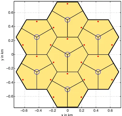
As depicted in figure 1 the investigated network consists of 7 macro sites with 3 sectors each. Each sector acts as a separate BS why in the following the term MBS always refers to a macro sector. Within each sector a PBS is placed. In case CBF is used, each PBS cooperates with the corresponding sector it is placed in.
−0.6 −0.4 −0.2 0 0.2 0.4 0.6
−0.6
−0.4
−0.2 0 0.2 0.4 0.6
x in km
[image:3.612.339.537.224.413.2]y in km
Fig. 1. Network layout: Red points mark a PBS, blue circles indicate a macro site hosting 3 MBS
The distribution of the MSs is done according to the so called hotspot distribution with 20 MS per macro BS. 2/3 of them are placed in the vicinity of a PBS while the remaining 1/3 is placed randomly in the simulation area. This is a standardized simulation assumption ([7], Table A.2.1.1.2.-4/5) which reflects that PBS will be installed at locations with high MS density.
C. Scheduling
The scheduler operates within both PBS and MBS. In the case of cooperation the schedulers of the cooperating BSs work together as it will be described in section III-B, otherwise it operates autonomously. Its task is to assign the physical resource blocks (PRBs) as used in LTE-A to the MSs. This happens in every time transmission interval (TTI) which is 1 ms.
D. MS Feedback
at the scheduler (in the BS), LTE-A uses feedback from the MSs. According to the currently implemented specifications LTE-A uses implicit channel feedback which means that the MSs estimate suitable transmission parameters and report them to the BS. The name implicit channel feedback reflects that the BS does not have exact knowledge about the channel to the MS. Out of the transmission parameters the BS can only implicitly estimate the channel conditions.
However, the CBF algorithm which is investigated in this work, requires explicit channel information, namely the chan-nel transfer function. This is a common requirement for coor-dinated multipoint (CoMP) algorithms. [8] mentions explicit channel feedback for future implementation. As explained and motivated in the introduction, explicit feedback is used here. The MSs report a quantized transfer function of the channel they experience. Details on the feedback method that was used can be found in [9]. A reporting sub-band size one PRB is used which means that the MSs report one value on the channel direction (phase) and magnitude per PRB. The number of feedback bits is not restricted (the exact information is used with double precision).
E. Link Adaptation and Precoding
After assigning PRBs the transmission parameters have to be set. This consists of two parts:
• LA: Choosing an MCS which fits best to the SINR at
the scheduled PRBs. According to the LTE-A standard it is only possible to choose one MCS per MS. If an MS has been assigned multiple PRBs with varying SINR (or if the SINR varies within one PRB) it is not possible to choose different MCSs for the different PRBs. Instead a compromise must be found. There are two options for LA in the used SLS:
– Ideal LA (ILA): The BS chooses the best MCS
directly before the transmission using perfect channel knowledge. This does not reflect a realistic imple-mentation. However, it can be used to find the upper bound of the performance.
– Realistic LA: The BS uses the feedback from the
MS also for LA. Out of the feedback it estimates the SINR that the MS is experiencing and selects an MCS. This behaviour models real networks. Due to several reasons (e.g. feedback delay, quantization) the MCS chosen is not necessarily the best one.
• Precoding: The modulated symbols are multiplied with
the precoder before transmission. The precoders are de-signed as follows:
– Beamforming: The precoder ensures that the signals
of the BS antennas sum up constructively at the MS’s location.
– CBF: The precoder at a BS can be calculated to
reduce interference of this BS to MSs that are served by other BSs (for details see section III-B).
There is currently no option for precoding based on ideal channel knowledge in the SLS. The calculation of
precoders is therefore always based on feedback from the MSs.
III. COORDINATEDBEAMFORMINGALGORITHM AND
SCHEDULER
A. Coordinated Beamforming Algorithm
A CBF algorithm based on CSI sharing is given in [6]. It is designed for a system with two BSs and two MSs (see figure 1 in [6]). It describes how the precoders at both BSs should be chosen in order to avoid interference from BS 1 to MS 2 and from BS 2 to MS 1. To use it in a system with multiple BS and MS it was combined with a round-robin scheduler as described in the following section.
B. Coordinated Beamforming Scheduler
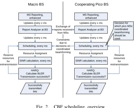
Figure 2 shows an overview of the CBF scheduling process.
MS Reporting, enhanced
Report Analyzer at BS
Scheduling, every ms Updates every x ms
Updates every x ms
SINR calculation, every ms Resource Assigment
HARQ: Calculate BLER Transmission successful?
Successfully transmitted
bits Reserve
resources for restransmission
Macro BS Cooperating Pico BS
MS Reporting, enhanced
Report Analyzer at BS
Scheduling, every ms Updates every x ms
Updates every x ms
SINR calculation, every ms Resource Assigment
HARQ: Calculate BLER Transmission successful?
Successfully transmitted
bits
Reserve resources for restransmission Exchange of
reports received from MSs
Constraints due to decisions on coordinated beamforming
[image:4.612.318.545.273.455.2]Decision for which pico MSs coordinated beamforming should be used.
Fig. 2. CBF scheduling, overview
The concept of the scheduling algorithm is as follows:
• 9 dB range expansion for the PBSs is used. As a result
there is only low interference from PBSs to macro MSs (MMSs) (because all MSs that receive a PBS with an acceptable power connect to it) but very high interference from MBSs to PMSs. Therefore the scheduling algorithm was designed in order to mitigate interference from MBSs to PMSs.
• One MBS cooperates with one PBS. The implementation
of this cooperation is: Before assigning resources, the scheduler at the MBS triggers the scheduler for the PBS. The PBS scheduler can then decide if CBF should be applied and give corresponding constraints to the MBS scheduler.
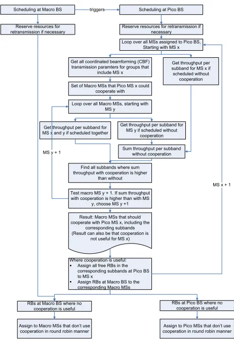
• The scheduler at the PBS first calculates how many PBRs
calculate precoders which mitigate the interference from MBS to PMS and from PBS to MMS. The CBF algorithm does not suppress interference from other BSs than the cooperating one. Using the precoders, the SINR for PMS and MMS when using CBF can be estimated. This gives an indication about the estimated throughput. The same is done using the precoders for normal (not coordinated) beamforming. By comparing the estimated throughputs the decision on the usage of CBF is taken. The current implementation uses CBF if the sum throughput of PMS and MMS is higher with than without CBF. If there are multiple groups with a gain when using CBF, the one with the highest sum throughput is chosen.
• When the PBS scheduler decided that CBF should be
[image:5.612.57.288.268.606.2]used for a group of PMS and MMS, the corresponding PRBs are reserved at PBS as well as MBS.
Figure 3 shows the scheduling process in detail.
Scheduling at Macro BS triggers Scheduling at Pico BS
Reserve resources for retransmission if necessary
Loop over all MSs assigned to Pico BS, Starting with MS x
Get all coordinated beamforming (CBF) transmission paramters for groups that
include MS x
Set of Macro MSs that Pico MS x could cooperate with
Get throughput per subband for MS x if scheduled without cooperation
Loop over all Macro MSs, starting with MS y
Get throughput per subband for MS x and y if scheduled together
Get throughput per subband for MS y if scheduled without
cooperation
Sum throughput per subband without cooperation
Find all subbands where sum throughput with cooperation is higher
than without
Test macro MS y + 1. If sum throughput with cooperation is higher than with MS
y, choose MS y +1 MS y + 1
Result: Macro MSs that should cooperate with Pico MS x, including the
corresponding subbands (Result can also be that cooperation is
not useful for MS x)
Where cooperation is useful: Assign all free RBs in the corresponding subbands at Pico BS to MS x
Assign RBs at Macro BS to the corresponding Macro MSs
MS x + 1 Reserve resources for
retransmission if necessary
RBs at Macro BS where no cooperation is useful
RBs at Pico BS where no cooperation is useful
Assign to Macro MSs that don’t use cooperation in round robin manner
Assign to Pico MSs that don’t use cooperation in round robin manner
Fig. 3. Detailed CoMP scheduling process
IV. SIMULATIONRESULTS
To investigate the impact of CBF a heterogeneous macro / pico network, modelled as described in section II, was simulated with and without CBF. For the case without CBF a round-robin scheduler was used, meaning that each BS independently assigns an equal number of PRBs to its MSs. The simulation assumptions can be found in table I.
TABLE I
TABLE1. SYSTEMLEVELSIMULATIONPARAMETERS
Parameter Value
Inter Site Distance 500 m (3GPP case 1) System Bandwidth 10 MHz, DL MBS transmit power 46 dBm Antennas at BS and MS 2
MBS antenna pattern 3GPP 2D ant. model with 14 dBi max. gain PBS transmit power 30 dBm
PBS antenna pattern Omni directional with 10 dBi gain Channel and Propagation
Model
ITU-R M.2135 Urban Micro (PBS) / Urban Macro (MBS) [10]
Number of PBS per sector 1
MS receiver type Maximum Ratio Combining
Transmission scheme Transmit beamforming with 2 antennas Traffic Model Full buffer
A. Expectations
The target of the CBF scheduler is to mitigate interference from MBS to PMS. This should directly increase the SINR of the PMS. As a consequence, the LA should be able to choose a higher MCS for the PMS which should then result in a higher throughput of the PMS. It can occur that the scheduler uses CBF even if it reduces the SINR of a MMS (in case the gain for the PMS overcompensates the loss of the MMS). Reductions in SINR of MMS are therefore possible.
B. SINR
Figure 4 shows the SINR distribution in the network with an without CBF. As expected a gain in SINR for PMSs is obtained. For MMSs there are slight deviations but no significant changes due to CBF. This is reasonable as the CBF scheduler was not intended to change MMSs SINR.
−010 −5 0 5 10 15 20 25 30 35
0.1 0.2 0.3 0.4 0.5 0.6 0.7 0.8 0.9 1
SINR values in dB
Probability { SINR values < Abscissa }
[image:5.612.318.557.439.591.2]PMSs with CBF MMSs with CBF PMS w/o CBF MMS w/o CBF
Fig. 4. Distribution of SINR with and without CBF
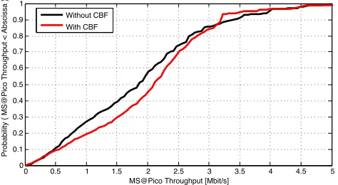
C. MS Throughput
As described in section II-E there are two options for LA in the used SLS: ILA and LA based on MS feedback. Figure 5 shows the PMS throughput distribution when using LA based on MS feedback. The gain in SINR (see figure 4) does not translate into a gain in throughput as expected.
0 0.5 1 1.5 2 2.5 3 3.5 4 4.5 5 0
0.1 0.2 0.3 0.4 0.5 0.6 0.7 0.8 0.9 1
MS@Pico Throughput [Mbit/s]
Probability { MS@Pico Throughput < Abscissa }
[image:6.612.55.294.56.188.2]Without CBF With CBF
Fig. 5. Distribution of PMS throughput with and without CBF using LA based on MS feedback
the first retransmission when the inital (1.) transmission failed. The BLER increases from 11.49% without CBF to 19.29% with CBF. A higher BLER directly reduces the MS throughput as it only counts successfully received bits.
TABLE II
BLOCK ERROR RATE WITH AND WITHOUTCBF
without CBF with CBF
BLER for 1. transmission: 11.49% 19.29% BLER for 2. transmission: 0.55% 4.03% BLER for 3. transmission: 0.10% 1.64%
In contrast, figure 6 shows a PMS throughput gain for CBF that is obtained with ILA.
0 0.5 1 1.5 2 2.5 3 3.5 4 4.5 5
0 0.1 0.2 0.3 0.4 0.5 0.6 0.7 0.8 0.9 1
MS@Pico Throughput [Mbit/s]
Probability { MS@Pico Throughput < Abscissa }
Without CBF With CBF
Fig. 6. Distribution of PMS throughput with and without CBF using ILA
The simulation results show that a gain in SINR for PMSs is achieved as intended. This proves that CBF is an option to mitigate the strong interference from MBSs to PMSs in het-erogeneous networks. However, without the (unrealistic) ILA, this does not translate into a gain in throughput. Therefore it is an important next step to deeper analyse of the problems in LA caused by CBF. Besides there a several fields to investigate:
• Currently CBF is used when the sum throughput of the
MMS and the PMS with CBF exceeds the one without. Other options for this decision should be taken into account: It could be especially important to use CBF for some PMSs that would otherwise suffer from very strong interference.
• The interference situation when using CBF should be
analysed in more detail: How strong is the interference mitigation? How strong is the remaining interference from the MBS compared to interference from other BSs?
• Positioning of PBSs: The position of the PBS within the
macro sector influences the interference from the MBS. How much does this influence the CBF gain?
• Investigation of other CBF algorithms: The currently used
CBF algorithm is designed for a two BSs and two MSs scenario, not like in the network simulated here. The authors of the algorithm mention in the conclusion of [6] that they currently extend their work to more than two-cell scenarios.
V. CONCLUSION
This paper described a CBF scheduler for a heterogeneous macro / pico network and gave initial simulation results. The target of the scheduler is to reduce the severe inference from MBSs to PMSs that occurs in heterogeneous macro / pico networks. From the simulation results it can be seen that a reduction of interference is feasible. However, a new challenge is introduced: Due to problems with the LA a higher block error rate is caused which reduces the throughput. This motivates detailed future work on an improved LA and the feedback needed therefor. Additionally several important steps to improve the presented scheduling were listed and will be implemented in future work.
REFERENCES
[1] A. Damnjanovic, J. Montojo, Y. Wei, T. Ji, T. Luo, M. Vajapeyam, T. Yoo, O. Song, and D. Malladi, “A survey on 3GPP heterogeneous networks,”IEEE Wireless Communications, vol. 18, no. 3, pp. 10–21, Jun. 2011.
[2] D. Lopez-Perez, I. Guvenc, G. de la Roche, M. Kountouris, T. Quek, and J. Zhang, “Enhanced intercell interference coordination challenges in heterogeneous networks,” IEEE Wireless Communications, vol. 18, no. 3, pp. 22–30, Jun. 2011.
[3] A. Ghosh, N. Mangalvedhe, R. Ratasuk, B. Mondal, M. Cudak, E. Vi-sotsky, T. Thomas, J. Andrews, P. Xia, H. Jo, H. Dhillon, and T. Novlan, “Heterogeneous cellular networks: From theory to practice,” IEEE Communications Magazine, vol. 50, no. 6, pp. 54–64, Jun. 2012. [4] U. Jang, H. Son, J. Park, and S. Lee, “CoMP-CSB for ICI Nulling
with User Selection,”IEEE Transactions on Wireless Communications, vol. 10, no. 9, pp. 2982–2993, Sep. 2011.
[5] D. Lee, H. Seo, B. Clerckx, E. Hardouin, D. Mazzarese, S. Nagata, and K. Sayana, “Coordinated multipoint transmission and reception in LTE-advanced: deployment scenarios and operational challenges,”IEEE Communications Magazine, vol. 50, no. 2, pp. 148–155, Feb. 2012. [6] C.-b. Chae, I. Hwang, R. W. Heath, and V. Tarokh, “Jointly optimized
two-cell MIMO systems,” in2011 IEEE GLOBECOM Workshops (GC Wkshps). IEEE, Dec. 2011, pp. 421–425.
[7] 3rd Generation Partnership Project, “TR 36.814 Further advancements for E-UTRA physical layer aspects v 9.0.0,” Tech. Rep., 2010. [8] ——, “TR 36.819 Coordinated multi-point operation for LTE physical
layer aspects version 11.1.0,” Tech. Rep., 2011.
[9] P. Frank, A. Muller, and J. Speidel, “Fair performance comparison between CQI- and CSI-based MU-MIMO for the LTE downlink,” in
2010 European Wireless Conference (EW). IEEE, 2010, pp. 93–98. [10] ITU-R, “Guidelines for evaluation of radio interface technologies for
[image:6.612.59.296.405.535.2]