Microalloyed Steels
[an invited review for Ironmaking and Steelmaking ]
T.N. Baker
Metallurgy and Engineering Materials Research Group
Department of Mechanical and Aerospace Engineering
University of Strathclyde
Glasgow
G1 1XJ.
21 September 2015
Abstract
This review considers the compositions, the main process routes,
microstructure, and structural properties of microalloyed steels. The
background and brief history are followed by sections dealing with aspects of
precipitation which control grain size and dispersion strengthening in ferrite-
pearlite steels, the approaches to modelling thermomechanical processing and
the influence of multiple additions of transition metals on properties. High
strength acicular ferrite/bainite steels used for linepipe are included and lead to
super bainite steels. Around 12% of the world strip production is processed by
the thin slab direct charging route, which is considered in some detail. The
weldability of microalloyed steels now embraces joining using friction stir
Over the years, many approaches have been developed to predict the structural
properties of microalloyed steels. They comprise several quantifiable
microstructural features including atom clusters, relatively recently identified
through atom probe tomography. A comprehensive collection of references is
provided.
Keywords Niobium, vanadium, titanium steels ;Thermomechanical Processing; Microstructure; Structural properties; Acicular ferrite and bainitic steels; Thin slab direct charging; Friction stir welding; Components of strengthening; Reviews.
1 Introduction
This review follows two previous reviews by the present author on
‘microalloyed steels’.1,2
Since the second of these was published in 1992, an
excellent book by Gladman 3 and several reviews closely related to
microalloyed steels have appeared.4-7 Also, reviews on specific elements in
microalloyed steels have been published. These include the influence of
additions in microalloyed steels of niobium by DeArdo8, an overview of
titanium microalloyed steels by Pickering9 and reviews of vanadium by
Langneborg et al10, 11 and Baker12, and of zirconium by Baker 13, together with
these publications deal with microalloyed steels having a ferrite-pearlite (FP)
microstructure.
What therefore is new and justifies yet another review? In the intervening years,
there has been a continual drive to produce high strength structural steels at a
lower cost. Therefore microalloyed steels have progressed in several directions.
A better understanding of the role of both the microalloying additions and the
deformation processes, usually hot rolling, has been sought. Thermomechanical
processing has been refined through a better understanding of the relationships
between processing parameters, especially those involving controlled rolling,
and microstructure and properties. Direct charged thin slab processing of
microalloyed steels is an example of a developing route, (by 2007, 12% of the
World’s strip), which for some products, is more economic and has
environmental advantages over conventional processes. The extension of high
strength microalloyed steels into non-F-P microstructures, having yield
strengths (σy ) >500MPa, for such applications as pipe-line and automobiles is
well advanced. However, the application of friction stir welding to
microalloyed steels, which reduces residual stresses associated with the fusion
welding processes, is at much earlier stage of commercial exploitation. At a
fundamental level, the strength contributions from nano-precipitates is being
investigated, which, in some cases, may change the way estimates of
of hot working processes involving microalloyed steels is a work still in
progress. All these areas will be included in this review. However, with
~130,000 hits on Google for ‘microalloyed steels’, the work reviewed is
inevitably selective. It is based on well-cited papers that the author has been
aware of for some time, and recent papers that make a novel contribution to the
field from the many research groups world-wide, that I follow.
2. Background
The estimated world production of steels of all classes for 2014 is about
1.65 billion tonnes, of which 50% is accounted for from China.15 Of this
total, an ~12%, equal to some 200 million tonnes, a substantial component,
is made up of microalloyed steels.16
Compared to mild steel, with a lower yield strength, σy, of 150-200 MPa,
current microalloyed steels have σy values in the range of 350 to 800MPa,
with the potential to exceed 1000MPa. 17
Microalloyed (MA) or High Strength Low Alloy (HSLA) steels prior to the
1980’s, contained typically, 0.07 to 0.12% carbon, up to 2% manganese and
small additions of niobium, vanadium, titanium, (all usually max. 0.1%) in
various combinations.18 (The steel compositions are given in wt.-%, throughout
include molybdenum, zirconium, boron, aluminium, nitrogen and rare-earth
metals.
Vervynct et al 7 compiled a useful table of alloying elements normally present in
microalloyed steels, which, with the addition of zirconium and boron, is
reproduced in Table 1. The microalloying elements are used to refine the grain
microstructure and /or facilitate dispersion strengthening through precipitation.
They are normally regarded as having a low hardenability effect.19
Table 1 Alloying elements frequently used in microalloyed steels
Element Wt-% in steel Influence
C <0.25 strengthener
Mn 0.5-2.0 delays austenite decomposition during accelerated cooling
decreases ductile to brittle transition temperature strong sulphide former
Si 0.1-0.5 deoxidizer in molten steel solid solution strengthener Al <0.02 deoxidizer
limits grain growth as AlN
Nb 0.02-0.06 very strong ferrite strengthener as Nb(C,N) delays γ→α transformation
Ti 0-0.06 γ grain size control by TiN strong ferrite strengthener
N <0.012 forms nitrides and carbonitrides with Mo 0-0.3 promotes bainite formation
ferrite strengthener
Ni 0.0.5 increases fracture toughness Cu 0-0.55 improves corrosion resistance ferrite strengthener
Cr 0.1.25 with Cu, increases atmospheric corrosion resistance B 0.0005 promotes bainite formation
Controlled additions of sulphur, and occasionally tellurium, are also added to
improve the machinability.19 The original aim was to develop high strength and
toughness in FP steels in the as-rolled condition. Owing to their superior
mechanical properties, they allowed a more efficient design, with improved
performance, even under difficult environmental conditions. Furthermore, they
permit reductions in component weight and manufacturing cost. For more
information on the physical metallurgy of the elements of importance in
microalloyed steels, attention is drawn to the book by Gladman.3
To avoid any confusion, the present writer prefers to avoid the use of the term
‘high strength low alloy steels, HSLA steels’, and use ‘microalloyed steels’ to
describe those with micro-additions of niobium, titanium , vanadium and
zirconium, either singly or in combination, forming carbides, nitrides or
carbonitrides, with a face-centred cubic structure. Low alloy steels, a much
earlier defined class of steels than microalloyed steels, are generally regarded as
(0.5-2.5%),Mo ≤ 3% and V ~1%. These steels were developed as creep resistant
steels, but had an upper temperature limitation < 400°C, with applications, as
discussed by Oakes and Barroclough20, in the earlier British aero gas turbines,
and by Robertson21, in coal power energy producing plants. The Cr Mo grades
were normalised, while the Cr Mo V types were used in the normalised and
tempered condition, to develop the alloy carbides in a bainitic microstructure,
which conferred their particular properties. While the earlier microalloyed
steels sought to avoid transformation to acicular ferrite and bainite, modern
microalloyed steels, built upon a sounder understanding of the processing routes
and the development of microstructure than was available prior to the 1980’s,
embrace these phases17.
In microalloyed steels, FeNb consumption has grown threefold during the last
25 years and the most part of this growth has been noticeable over the past ten
years. Fig 1 shows the trend in ferro-niobium production. Also, the
development of microalloyed steels was far greater and far quicker for flat
products than for long products. 22
The material is produced preferably by a thermomechanical rolling process, also
known as controlled rolling, possibly with accelerated cooling, which maximize
grain refinement as a basis for improved mechanical properties. Prior to
thermomechanical processing, the steel was heated into the austenite
forming, the material must be quickly cooled to 600°C to 540 °C.18 Medium
carbon directly quenched (DC) microalloyed steels, avoiding FP
microstructures, can also be forged. 23
Microalloyed steels lie, in terms of performance and cost, between carbon steel,
or mild steels and low alloy steels mentioned above. Until around 1980, low
alloy steels were designed to have a yield strength between 500 and 750 MPa
without heat treatment. The weldability is at least equal to that of mild steel,
and can be improved by reducing carbon content while maintaining strength.
Fatigue life and wear resistance are superior to similar heat-treated steels. The
disadvantages are that ductility and toughness are not as good as quenched and
tempered (Q&T) steels.18
Cold-worked microalloyed steels do not require as much cold working to
achieve the same strength as other carbon steels; this also leads to greater
ductility. Hot-worked microalloyed steels can be used from the air-cooled state.
If controlled cooling is used, the material can produce mechanical properties
similar to Q&T steels. Their machinability is better than Q&T steels because of
their more uniform hardness and their FP microstructure.18 Because FP
microalloyed steels are not quenched and tempered, they are not susceptible to
quench cracking, nor do they need to be straightened or stress relieved.
However, because of this, they are through-hardened and do not have a softer
Current UK standards which contain specifications for microalloyed steel
grades are BS EN 10025-3:2004 & BS EN 10025-4: 2004 (UK/EU).
Industry-specific grades include: C38, C38 Modified (includes Tellurium), C42, C42
Modified (includes Tellurium), 49MnVS6, VanardTM series and HypressTM
series (for narrow strip products).18 Table 2 gives the mechanical properties for
various grades of pipeline steels discussed throughout this paper.
Table 2
Mechanical properties for pipeline steels
Grade YS (MPa) TS (MPa) YR (%) El%
X65 ≥448 ≥ 530 ≤90 ≥ 24
X70 ≥482 ≥565 ≤ 90 ≥ 23 X80 ≥551 620- 827 ≤93 ≥ 22 X100 ≥690 ≥760 90
X120 ≥883 ≥ 1023 90
3. History of microalloyed steels
The main development of microalloyed steels has taken place over the past 50
years, and was initially concentrated on niobium additions. The term
microalloying, as applied to steels, is generally accepted as emanating from the
paper by Beiser 24 published in 1959, which reported the results of small
additions of niobium to commercial heats of a carbon steel. However, it has not
when small additions of zirconium were added to plain carbon steels, and the
effects reported by Field 25,26 and by Beckett 27. Like many other scientific and
engineering innovations, military conflict was also the driving force in the case
of the development of zirconium steels. During the period of a few years
immediately preceding the entry of the United States into the First World War
in 1918, the US War Industries Board decided upon an intensive experimental
programme with the aim of possible large scale production of zirconium steels
suitable for light armour. However, this appeared to be discontinued when the
conflict ended, and interest moved to low alloy Q&T steels, normally
containing chromium, molybdenum and vanadium additions of 0.5 to 3%.
Much of the early work on the niobium microalloyed steels, which re-emerged
in the late 1950’s and early1960’s, was concentrated in the USA and UK. In the
UK, the University of Sheffield, BISRA (British Iron and Steel Association)
based in Sheffield and Swinden Laboratories of the United Steel Corporation,
based nearby in Rotherham, all made significant contributions. The history of
this development has been well documented in an excellent review by Morrison,
5
who 28, together with Woodhead, 29 played a major part in understanding the
role of niobium carbide in contributing to dispersion strengthening and grain
refining of ferrite, leading to greater strength than found in mild steels. His
initial paragraph, which is quoted here, sets the scene: ‘In 1958, it was
division of the National Steel Corporation of the USA, had entered the
market with its GLX-W series of niobium–treated steels, the first steel
company in the world to do so. What made this development so special was
the very small, relatively low cost addition of niobium used, 0.005 to 0.03%,
and the relatively large resultant strengthening effect, combined with good
toughness. Also, the niobium was added to an ordinary semi-killed C–Mn
steel (mild steel or mild carbon steel) and changed its strength level from a
low yield strength of around 300 MPa to a high yield strength of up to 415
MPa for the GLX-60-W grade, equivalent to a conventional alloy steel.’
History has shown that some of the major advances owe their success to the
chance simultaneous appearance several, apparently disparate, facets. This was
certainly the case with microalloyed steels. The marketing by the Great Lakes
Steel Corporation in the USA occurred in the same decade as the series
of publications by Hall 30, Petch 31 and Cottrell 32, which provided the
first real understanding of the factors which control the strength, and to
some extent, the toughness of crystalline material.
The Hall–Petch equation conveniently allows σy, the lower yield stress, (or
often, in practice, the 0.2% proof stress) to be related to the ferrite grain size, d:
σy = σo + kyd
-1/2
where σo and ky are experimental constants. The Hall–Petch equation as a
basis for assessing the components of strengthening will be considered
later.
Over the same period, the first high resolution (0.8nm) transmission
electron microscope [TEM], the Siemens Elmiskop I, became available,
and in the UK, precipitation in Q&T low alloy steels was one of the first
areas studied using this new equipment. Electron micrographs had
appeared in a number of papers emanating from the USA prior to this
time. These were mainly concerned with steels, but apart from utilizing
the higher resolution then available compared with the optical
microscope, little attempt was made to extend the interpretation; this was
due mainly to the studies being based on surface replicas. Following the
pioneering work of Heidenreich33 in 1949, Hirsch, Horne and Whelan34
at Cambridge, successfully prepared thin foils of a number of alloys,
including steels. The theories of kinetic and dynamic diffraction contrast
were developed over a period of years, which allowed the details of
features observed in foil TEM specimens, such as grain boundaries,
dislocations and precipitates, to be interpreted.35 This is well described
by Hirsch36.
Over the past two decades, the electron back scattering diffraction
(ESBD) technique, originally devised for the TEM, has been widely
sub-grains and particularly their boundaries 37, through the availability of
versatile software. This has provided opportunities to quantify what
were regarded formerly as difficult phases, such as bainite and MA
(martensite/austenite) phase, which are important constituents in some
modern high strength/high toughness microalloyed steels.
A fourth factor was the developments associated with steelmaking and hot
rolling, the latter to be the main route for producing microalloyed steels. New
stricter procedures were needed to ensure niobium steels in particular, achieved
their potential properties. These involved a knowledge of the solubility limits of
niobium carbide and nitride 3,8, to ensure that the precipitates which formed
during casting, were taken into solution prior to rolling. This often involved
running soaking pits at higher temperatures than normal practice. Also, it soon
became apparent that the number of rolling passes and their temperature needed
to be controlled, and hence the birth of ‘controlled rolling’ 38-40
. Within a short
time, this led to the introduction of computer control in many other aspects of
steel-making, and later the application of the results of academic computer
modelling to aid the whole complex process of achieving a small, < 10 µm,
homogeneously distributed ferrite grains.41- 43
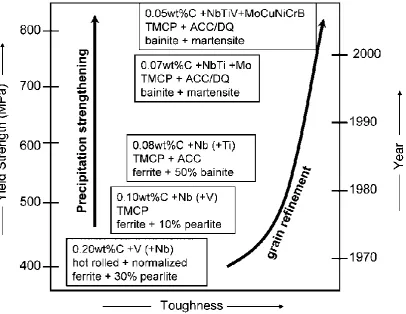
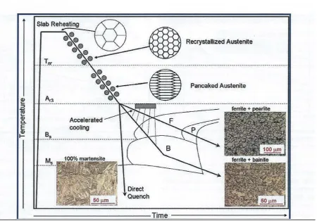
Fig 2 shows schematically how the microstructure and properties of plate
It is obvious from Fig. 2, that the accelerated cooling after rolling was largely
responsible for the very high strengths attainable, practically independent of
composition. With suitable cooling practices, σy levels >690 MPa (X100) can
be achieved in low C steels containing less than 2 wt-%Mn and with carbon
equivalent and weld cracking parameter near 0.5 and 0.2 respectively.6
4. Chemical compositions and precipitation in microalloyed steels
DeArdo et al 6 posed the question ‘what is the role of the microalloying element (MAE) in obtaining strength levels in these steels?’ It is answered by considering ‘the early steels (pre-1980), where air cooling of plate and high coiling temperatures of strip were used. As noted above, these were the FP steels with strengths up to ~420 MPa (X60) for gauges up to 18 mm. The most obvious contributor to strength was grain refinement, as was clearly shown by quantitative optical microscopy. There is no doubt that the MAE was responsible for this contribution through its effect on austenite conditioning. Other contributions included solid solution strengthening by the Mn, Si and others, including the MAE, when retained in solution. Equations have been published quantifying these effects.3 The other contribution to strength, claimed by researchers studying these early steels,
The precipitation of carbides and nitrides occur at three different stages during
the processing of microalloyed steels 2,3. Type 1 precipitates are formed during
the liquid phase and during or after solidification, on the liquid-solid interface
and in delta ferrite. These precipitates are very stable, and while they are
normally too large to influence recrystallization of austenite, the smallest may
effectively retard coarsening in austenite during reheating or during a welding
cycle.45
Type 11 particles are precipitated in austenite after solution treatment and
during hot deformation, such as controlled rolling, as the temperature is
decreasing.46 The precipitates are strain induced, and can retard the
recrystallization of austenite. Grain refinement of microalloyed steels is mainly
due to this group of particles. 47-49
Finally, Type 111 particles are formed during or after the austenite to ferrite
phase transformation, nucleating on the austenite/ferrite interface and in ferrite
50
. Dispersion strengthening in ferrite normally occurs through these changes
and a fine precipitate dispersion is usually observed.
The carbides and nitrides of the transition metals, which precipitate in
microalloyed steels, are B1 NaCl (Fm3m) type compounds. Several precipitate
nucleation processes have been recognized in microalloyed steels. These
include homogeneous precipitation, resulting in coherent precipitates with strain
precipitation, heterogeneous precipitation on grain boundaries and dislocations,
where the latter is often referred to as strain induced precipitation (SIP).
A pre-precipitation grouping of atoms, nano-precipitates, known as GP zones in
non-ferrous alloys and also described as ‘clusters’ in microalloyed steels, has
received increased attention over the past decade ,due to the development of
atom probe tomography(APT). Several APT studies on niobium microalloyed
steels have reported.51-56 These nano-precipitates are assuming importance, due
to the claim that they provide a significant contribution to the yield strength. 57
Following a 1250ºC homogenization, water quenching, and tempering at 600 ºC
in a salt bath for 300s,in a steel containing controlled atomic concentrations of
500ppm Nb and 250ppm C and N, monolayer GP zones were detected by
Danoix et al 53. These were platelets comprised of niobium and nitrogen atoms,
~ 4 x 4nm in size, lying on {100}α planes. The amount of iron and carbon in the
GP zone was ~ nil. They53 also claimed that the homogeneous nucleation
mechanism for the nitrides, which nucleated heterogeneously on dislocations,
was completely different from that of carbides. However, different results were
obtained by Breen et al55, who used APT to study a steel containing 0.03 C-
0.007N- 0.084Nb, finish rolled at 879 ºC and coiled at 567 ºC. Samples were
aged to investigate the Nb (C, N) precipitation in ferrite. Table 3 compares the
nano-precipitate composition following three ageing treatments. It can be seen
nano-precipitate, which had a similar composition to the nominal composition
of the steel. Even after ageing for 40 min at 700 ºC, the nano-precipitate size of
~2.6nm length by 2.8nm width, was still considered to be less than the critical
size for coherency loss with the ferrite matrix. As most microalloyed steels are
used in the as-rolled condition, it is relevant to examine how hot deformation,
rather than ageing, influences the development of nano-precipitates.
Table 3
Comparing the bulk composition measurements of C, N and Nb to the nominal
composition 55
Pereloma et al51,56 used APT to compare niobium clustering in a Nb-Ti
microalloyed steel, deformed above and below the non-recrystallisation
temperature, Tnr , which represents the start of the inhibition of complete static
recrystallization during cooling between rolling passes. Using a Gleeble
simulator, they studied a steel containing 0.081C- 0.064Nb-
0.021Ti-0.003V-0.017N. After austenitising at 1250 ºC and roughing at 1100 ºC, samples were
0.75, before cooling. Similar distributions of >70nm TiN and (Ti, Nb)(C,N)
were found in all specimens. 1075 ºC was too high for Nb-C clusters to form,
and therefore strain induced precipitation of NbC did not occur. However, after
825 ºC deformation, a relatively high number density of Nb-C clusters occurred,
as did SIP of NbC. This implies that the lower deformation temperature of 825
ºC resulted in a higher dislocation density, leading to an increase in the number
of nucleation sites for Nb-C clusters. These clusters might be considered as
precursors to SIP via heterogenous nucleation of NbC. The above work was
extended by Kostryzhev et al54, to include aspects of the strengthening of the
steel through the possibility of clusters being cut, which is discussed below.
Coherent precipitates are cut by dislocations, leading to a different strength
mechanism than incoherent precipitates. This distinction becomes very
important when estimating yield strength from microstructure.
Few observations of coherent precipitates in microalloyed steels have been
verified. This is in part, due to the very small size at which they lose coherency.
Coherency strain fields associated with transition metal carbides and nitrides
have very rarely been reported for precipitates in microalloyed steels, vanadium
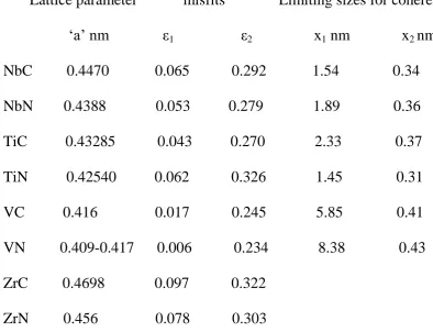
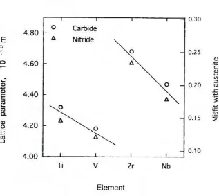
carbonitride 2 being an exception, Fig 3. Fig 4 shows that the calculated misfit
of vanadium carbide and nitride in austenite is much less than for niobium
carbide and nitride 58, 59. Estimates of the limiting size of some coherent
shows the size when coherency begins to be lost is significantly smaller for
NbC than VC. The estimated V-C cluster diameter is in the range 3-13nm,
[image:19.595.69.464.249.551.2]which is larger than that given for NbC in Table 4, based on misfit alone.
Table 4 – Estimated limiting sizes for coherency of platelet carbides and nitrides
found in ferrite in microalloyed steels
Lattice parameter misfits Limiting sizes for coherency
‘a’ nm ε1 ε2 x1 nm x2 nm
NbC 0.4470 0.065 0.292 1.54 0.34
NbN 0.4388 0.053 0.279 1.89 0.36
TiC 0.43285 0.043 0.270 2.33 0.37
TiN 0.42540 0.062 0.326 1.45 0.31
VC 0.416 0.017 0.245 5.85 0.41
VN 0.409-0.417 0.006 0.234 8.38 0.43
ZrC 0.4698 0.097 0.322
ZrN 0.456 0.078 0.303
ε1 and ε2 are the calculated strains parallel and perpendicular to the major axis
of the disc shaped particle of diameter x1 and thickness x2.
The data in Table 4 is based on the cube on edge orientation relationship first
established by Baker and Nutting (BNOR) for tempered steels 60:
(100)α // (100)MCN
and on the condition that coherency starts to breakdown when the strain at the
particle matrix interface equals the Burgers vector magnitude of a dislocation.
This is shown schematically 36 in Fig 5. The interfacial energy of B1 carbides
and nitrides having the B-N orientation relationship have been studied in detail
by Yang and Enomoto.58, 59 How this affects coherency is still unclear.
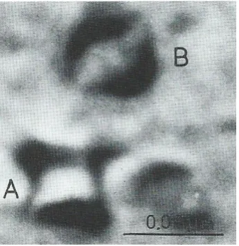
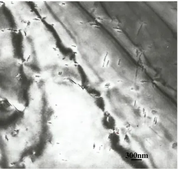
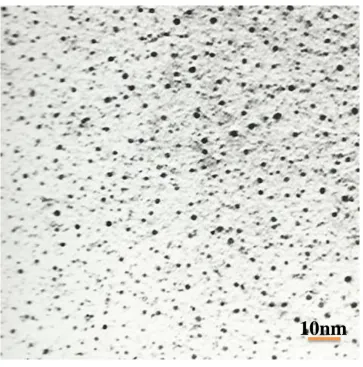
Incoherent disc precipitates of VN are seen in Fig 6, where strain fields are no
longer present. The fine NbC particles in Fig7, present on a replica, would
provide dispersion strengthening.
Interphase precipitation occurs during the transformation of austenite to ferrite
and is found, with the possible exception of ZrC and ZrN, for all the transition
metal carbides and nitrides, 50 as well as silver61 and copper 62 precipitates in
steels. Dunne 62 pointed out that the many studies by Honeycombe and
co-workers 50, usually with highly alloyed ternary or quaternary laboratory steels,
and often in the isothermally treated condition, producing high volume fractions
of precipitates, were undertaken to elucidate the fundamental mechanisms of
interphase precipitation. These are summarized in terms of the morphologies
which have been established:
1. interphase precipitation (planar)
2. interphase precipitation (curved)
3. continuous fibre/lath growth
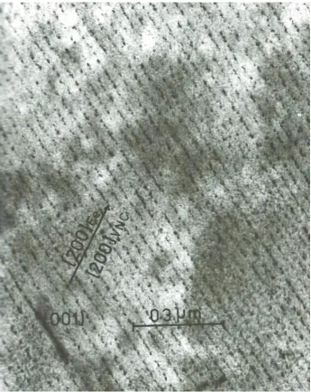
Planar interphase precipitation is typified by parallel sheets of densely
populated sheets, related to ferrite by the Baker and Nutting orientation
relationship 60, and appear to have a regular spacing, Fig 8. Continuous fibres
comprise parallel laths, akin to a very fine pearlite. Details of the mechanisms
have been reported in many publications, including refs.1-5, 11, 50, 61, 62.
While interphase precipitation is well established in isothermally transformed
steels, it appears to be less important in commercially processed Nb and Ti-Nb
as-rolled microalloyed steels. For these steels, this leaves heterogeneously
nucleated precipitation associated with grain boundaries, leading to grain
refining, and precipitation associated with dislocations (SIP) as the main classes
of precipitates. However, compared to the other microalloying elements,
vanadium has a much greater solubility in austenite, and therefore remains in
solution to a much greater extent during processing in the austenite range.
Vanadium–Carbonitride interphase precipitates which form above 700 ºC are
recognized as making an important contribution to strengthening, which
becomes general V(C, N) precipitation below 700 ºC. The fibrous morphology
of V(C, N) is sparse and is never a dominant microstructure. 11
Vervynct et al 7 considered the principal function of alloying elements in F-P
microalloy steels to be ferrite strengthening by grain refinement, dispersion
strengthening and solid solution strengthening, all implied by Petch 31. Solid
solution strengthening is closely related to the alloy content, while grain
alloy composition and thermomechanical processing. For example, the
strengthening effect of niobium, the most widely studied element in
microalloyed steels, occurs mainly by three microstructural mechanisms: ferrite
grain refinement due to austenite grain boundary pinning, retardation of
recrystallization, and dispersion strengthening 6. Each of these mechanisms will
be considered more fully below. In addition, alloying elements are selected to
influence the reduction in the temperature at which austenite transforms to
ferrite and pearlite during cooling. In this way, a fine grained product is
produced, which is a major source of strengthening and toughness.
DeArdo et. al,6 consider that ‘the year 1980 represents a bench mark in the
strength of microalloyed (MA) steels. From the early days of the 1960s to approximately 1980, the steels being micro-alloyed were low hardenability steels with FP microstructures and σy ≤ 420 MPa. These steels were used to
martensite, either as monoliths or as mixtures. To achieve these microstructures, the combination of higher hardenability and high cooling rates was required. Furthermore, much additional research was needed to reach the required goals consistently and with uniform results. From the processing side, the solution to this dilemma was using water cooling after hot rolling. This was accomplished in the mid-1980s for plate processing by interrupted accelerated cooling (IAC) 63,64 and interrupted direct quenching (IDQ)65 in plate mills, Fig 9. Runout table water spray cooling to the coiling temperature in hot strip mills had been in practice since the 1960s, but not as a microstructural control tool for increasing strength. This was because of the higher carbon contents of the steels of that era. The benefits of faster rates of cooling and lower coiling temperatures were exploited for achieving higher strengths later with steels of lower carbon contents’.
5. Controlled rolling and controlled cooling
The importance of developing a small grain size in terms of increases in both
strength and toughness is evident from the initial work of Hall 30 and Petch31
mentioned above. As stated by Llewellyn 66, ‘the traditional route (prior to the
1970’s) to a fine grain size in ferrite–pearlite structural steels has been to
incorporate grain refining elements, such as aluminium, and then to normalize
that ‘when normalizing was carried out on a niobium treated steel to improve
the impact properties, the strength advantage was forfeited. There was therefore
a need for an alternative route to a fine grain size in structural steel plate which
would overcome both the cost and strength penalties associated with traditional
normalizing. As described by Morrison5 'the key to obtaining a fine grain size
in a low niobium steel (~0.02wt%) is the low finishing rolling temperature,
which occurs naturally in thin plates and cross-country mills. Mackenzie 67, 68
collected data from 68 plates, finished rolled from 11 to 38mm, using 14 to 36
passes, which took between 3 and 6 mins in the mill, with finishing
temperatures between 800 and 1100°C. He found that finishing temperatures
below ~900°C gave acceptable notch ductility, equating to as-rolled plates
≤13mm in thickness. Fig. 10 shows that much greater thicknesses could be
tolerated in sections due to their lower rolling rate. As far back as 1958,
Vanderbeck 69 reported that ‘European steel producers were adopting lower than
normal finishing temperatures during rolling, in order to refine the
microstructure and improve properties’. The idea of using a rolling schedule to
produce a fine grain size may have originated from so-called cross-country
mills, a versatile ‘jobbing’ finishing mill, often used for producing sections or
bar in a steel works,where the work-piece usually passed only once through a
set of rolls, which were spread over a large area, with the final set some distance
of heat, and often the steel was black on reaching the finishing stand. However,
at Round Oak Steelworks in Staffordshire, it was noted that when the steel was
black at the finish of rolling, the strength and toughness properties were always
superior to when the steel finished red. It was on this mill that the writer
undertook some of his first controlled rolling trials in 1963.
‘Controlled rolling or rolling over a deliberately lowered temperature range
compared with conventional hot rolling, is now a widely accepted technique for
the production of microalloyed steels.’ This statement by Kozasu 70, 71 is as true
today as when it was first made in 1968, when the aim of controlled rolling was
to produce a steel with a fine polygonal ferrite grain size. Today, this is
extended to include acicular and bainitic microstructures.17
In his review of controlled rolling, Tamura 40 states that ‘the fundamental
difference between conventionally hot-rolled and controlled- rolled steels lies in
the fact that the nucleation of ferrite occurs exclusively at austenite grain
boundaries in the former, while it occurs in the grain interior, as well in the
latter, leading to a more refined grain structure.’
Conventional controlled rolling is an example of a TMPT which manage the
temperature and deformation during hot rolling, to control the austenite
microstructure at the start of transformation. Here, it is essential that
a high density of nucleation sites into austenite grains for nucleation of ferrite
grains, by hot rolling in the austenite phase field,
After transformation to ferrite and subsequent recrystallization, as first
described by Hanemann and Lücke 72, this leads to a refined microstructure.
Ferrite grain refinement is due to two mechanisms: (i) fine recrystallized
austenite grains formed by hot rolling at intermediate temperatures, and (ii)
austenite deformation below the recrystallization temperature, which enhances
the nucleation of ferrite.70
The first step in the controlled rolling process is to control the austenite grain
size during the soaking stage. This is set by the temperature which is necessary
to take into solution the microalloying particles, which have formed during
cooling following solidification during casting. As is well established, the
austenite grain size is related exponentially to the soaking temperature.
Therefore a balance exists between the temperature necessary to dissolve the
particles, the resultant austenite grain size and the economics of high soaking pit
temperatures.7,70 The importance of the correct soaking temperature for a given
steel is well illustrated by Lagneborg et al 8 for Ti-V-N steels. Reducing the
soaking temperature from 1250ºC to 1100 ºC reduced σy by ~40MPa and the
ductile-brittle transition temperature by 15 ºC, due to a reduction in the
Kozasu et al 70 divided the controlled rolling process into three ranges,
associated with changes in the austenite and ferrite grain structures.
1 Deformation in the austenite recrystallization temperature range.
Deformation above 1000°C normally develops coarse recrystallized austenite
grains, which transform to a relatively coarse ferrite and upper bainite. The size
of the austenite grain size obtained by recrystallization, decreases with
increasing strain, which is introduced by the rolling reduction, and eventually
reaches a limiting value.73
2. Deformation in the unrecrystallized range.
Deformation in the intermediate temperature range from 1000°C to 900°C
refines austenite by repeated recrystallization, leading to fine grained ferrite.
The austenite grains are elongated (pancaked)and deformation structures
result.74 A build-up of strain is often associated with the formation of twins or
deformation bands, which increase the number of potential sites for ferrite
nucleation and this, as mentioned above, is regarded as one of the most
important aspects of controlled rolling.40,75
3. Deformation in the (γ+α) two phase region.
Deformation below the recrystallization temperature produces ‘warm worked’
austenite, which leads to a finer ferrite grained microstructure. The third stage
deformation has a much larger influence on the final mechanical properties than
the first two stages. Rolling to just above the Ar3 temperature, can result in
recently formed grains. The transition temperature was shown to decrease in a
linear manner with an increase in total reduction in ranges 2 and 3.76
Kozasu et al 70, do not consider rolling below Ar1, or the changes in
microstructure in terms of the role of dislocations. This has been addressed
more recently Vervynckt et al 7.
An important concept, is the non-recrystallisation temperature, Tnr, which
represents the start of the inhibition of complete static recrystallization during
cooling between rolling passes. The most common method of determining Tnr,
consists of simulating successive rolling passes and representing the mean flow
stress (MFS) versus the inverse of the absolute temperature graphically for each
of the simulated passes, 7 as seen in Fig 11. Here Tnr, appears as a change in
slope of the MFS curve. Vervynckt et al 7, 75 proposed extending the controlled
rolling process to four regions, as defined in Fig 11. Data was obtained for a microalloyed steel containing 20ppm Ti and 18ppm N, based on a simulation of
a 23 plate rolling pass schedule, with fixed interpass times of 20s and a cooling
rate of 1°Cs-1. In Fig. 11 (a), the flow stress increases with decreasing
temperature in Region 1, while the curves change their shape entering
Region11. As strain increases and temperature decreases in Region 111, the
flow stress decreases, before increasing again in Region 1V. These are better
interpreted in Fig. 11(b) , where the mean flow stress (MFS) is plotted against
Region I corresponds to deformation at high temperature. Austenite
recrystallizes completely between passes and there is no accumulation of
dislocations. The increase in flow stress is solely due to the decrease in
temperature.
In Region II, the change in slope indicates that dislocations are being
accumulated. The flow stress increases more rapidly because of the inhibition
of recrystallization between passes.
Region III is characterised by a significant decrease in MFS, and corresponds to
the start of the γ→α transformation. Here the intercritical two–phase rolling
takes place.
Region IV corresponds to warm rolling in ferrite.
The intersection of the straight regression lines fitted to regions I and II defines
Tnr, that fitted to regions II and III defines Ar3, and that fitted to regions III and
IV defines Ar1. These are only for the conditions used here; i.e. fixed interpass
times of 20s and a cooling rate of 1°Cs-1.
Hot rolling takes place on a falling temperature gradient, and the influence of
the recrystallized state of austenite on the transformation behaviour and CCT
curves of microalloyed steels was first investigated by Smith and Siebert.77
They showed that the ferrite start line, Ar3, was shifted to shorter times when
austenite was in the unrecrystallised state. Mixed ferrite grain sizes were found
when large strains were introduced in a temperature range in which only a
unrecrystallized grains transformed, i.e. <Tnr, usually lead to ferrite of a
different grain size, from the ferrite originating from the recrystallized austenite
in adjacent regions.
The state, or condition of the austenite prior to transformation, is therefore one
of the major factors that determines the ferrite grain size. In addition to the
grain size of austenite, the potential ferrite nucleation sites must be taken into
account in any relationship with the ultimate ferrite grain size. Priestner and de
los Rios 78 introduced the term Sv, which is the grain boundary surface area per
unit volume of austenite, also described as the ʻeffective grain size’, to account
for the elongated grains. Sv is now often used to include boundary and
intragranular nucleation sites.71 Austenite which has a large value of Sv would,
by definition, have a large capacity for nucleation of ferrite, and as has been
pointed out by De Ardo 79, a low hardenability, and would be expected to
develop a fine ferrite-pearlite microstructure. This concept is supported by
experimental data, 78 Fig 12.
Final deformation in the low temperature austenite is the temperature range
within which complete static recrystallization no longer takes place between
rolling passes, leading to the retention of work hardening.
Jonas and Sellars, 43 explain succinctly that
‘
thermomechanical controlled processing in industrial practice involves the production of specificmicrostructures, which are associated with particular mechanical and physical
properties. In this way, TMCP differs from traditional deformation processing,
which is generally concerned with reductions in thickness and with developing
desirable changes in shape. TMCP involves the control and interaction of the
following fundamental mechanisms: dislocation glide and climb,
recrystallization, grain growth, phase transformation, precipitation, particle
coarsening, particle pinning and solute drag. The interest in many of these
structural changes is whether they take place dynamically (i.e. during
deformation) or statically (i.e. after deformation). TMCP is concerned with the synthesis of these fundamental mechanisms. Of particular interest to
microalloyed steels, is the TMCP operation concerned with grain refinement for high strength and toughness. Two contrasting, but complementary approaches have been taken; laboratory simulation and computer modelling. The former
involve compression, tensile or torsion testing. Compression testers are useful
for the determination of the kinetics of recrystallization or precipitation, while
tensile machines are used to measure hot ductility, leading to the determination
of the temperature and strain rate ranges associated with optimum workability.
Computer modelling aims to quantify the fundamental mechanisms involved in
TMCP, in terms of the variables of temperature, strain, strain rate and time, and
forming processes. The inclusion of the parameters of microstructural features
is now widely accepted as essential, both for off-line optimization of processing
conditions, and for on-line control. In the case of hot rolling of steels, the
modelling process involves sequential deformation passes taking place over a
range of temperatures, rolling speeds, and interpass times.’
As explained by Sellars42, ‘during the hot deformation process itself, e.g. a
rolling pass, work hardening takes place but it is balanced by the dynamic
softening processes (i.e. during deformation) of recovery and recrystallization. These processes, which are thermally activated, lead to a flow stress that
depends on strain rate and temperature, as well as strain. The microstructural
changes taking place within the material result in an increase in dislocation
density with strain, causing dynamic recrystallization, which takes place
repeatedly as new recrystallized grains are themselves work hardened. These
dynamic microstructural changes leave the metal in an unstable state and
provide the driving force for static recovery and static recrystallization to take
place after the deformation pass. Static recrystallization may be followed by grain growth, if the temperature is sufficiently high. Sellars 42 poses two
important questions, which must be answered to apply the above principles to
commercial practices: ‘(a) how long does recrystallization take after a
deformation pass; and (b) what grain size is produced by recrystallization and
grain growth? The answers determine the microstructure of the material
the material and the working forces required. Eventually they determine the
microstructure and properties of hot worked products.’ Details of the
application of this approach is given by Sellars 40 and in a shorter form by Jonas
and Sellars 43.
Depending on the eventual product, after casting and solidifying into an ingot,
the steel is further processed by rolling (or forging). The rolling process
requires the ingot to be reheated (soaked) before primary rolling to a smaller
intermediate size (billet), which is cooled to ambient temperature. Normally,
the steel is finish rolled in a different mill at a later time, and it is at this stage
that the controlled rolling process is undertaken.
To make the forming process easier, relatively high soaking temperatures are
traditionally employed for primary rolling, which causes considerable grain
growth. Therefore the first step in controlled rolling is to control the austenite
grain size, which increases exponentially with temperature, during reheating.
The temperature should be sufficient to take into solution the microalloying
elements, as discussed in detail in a later section.
From a commercial aspect, the modelling must relate to (a) the stock soaking
temperature and time (b) the rolling schedule in terms of rolling velocity,
deformation per pass, temperature at entry of rolling stock to each pass, interval
between passes, and final rolling temperature, and (c) the cooling rate following
Vervynckt et al 7 describe Tnr, the non-recrystallization temperature, as
representing the start of the inhibition of complete static recrystallization,
during cooling between rolling passes. They also considered the experimental
methods for the determination of Tnr, and note that most measurements of this
parameter relate to plate mill schedules, which are easier to simulate by
laboratory test methods due to their long interpass times of 10-20s, compared to
strip mills. They consider that new experimental methods are essential to
determine Tnr for strip mills, with their short (1s) interpass times. In
microalloyed steels, the initiation of strain induced precipitation, (SIP), which is
the normally considered as the nucleation of carbides, nitrides and/or
carbonitrides on dislocations introduced by deformation, has the ability to
suspend both static and dynamic recrystallization. In other words, SIP, strongly
influences Tnr. He also points out that continuing deformation also leads to
coarsening of existing precipitates, and that ‘fresh’ precipitates are generally
considered to be necessary for preventing recrystallization. This effect is
important in modelling of rolling operations, because the interruption of both
static and dynamic recrystallization leads to increases in rolling loads, whereas
the initiation of dynamic recrystallization in the absence of precipitation, results
in a sudden decrease in rolling load. It should be noted that the models
developed for controlled rolling processes which involve precipitation, normally
do not include coherent precipitation or interphase precipitation, but only
A different approach has been adopted by Matlock and Speer. 80 They started
from the product, in their example, long bars, and then developed a
microalloying and processing strategy for their manufacture. In this way, they
considered that it was more likely that strategies which are less successful could
be avoided. While this is a far less rigorous approach than the modelling
described above, it does have the merit of being applicable to a very wide range
of steel compositions and processes, associated with microalloying. These
include thermomechanical processing of steel bars, which involves forging, and
the production of reinforcing bars. Matlock and Speer 80 also considered the
process route of a range of products, such as automotive springs and
components for automotive engines and transmission systems, which require
quenching and tempering, and high temperature carburising.
7. Solubility of particles which control grain size and
provide dispersion hardening.
As mentioned earlier, the soaking temperature, prior to rough rolling, must be
sufficient to take into solution the microalloying elements. In microalloyed
steels, the most important particles are carbides and nitrides, of the transition
metals, niobium, titanium, vanadium and to a considerably lesser extent,
zirconium. These are often present as carbonitrides. In certain cases, oxides of
During processing, the lowest temperature for taking into solution the particles
precipitated on casting, which are later to control grain size and dispersion
strengthening, is determined by their solubility in iron as a function of
temperature and time. Matlock and Speer 80, in defining a strategy for the
application of microalloying to a range of products, summarised the main
objectives of adding niobium, titanium and vanadium to steels with a spectrum
of carbon contents, relevant to long products. For example, they considered that
the main precipitates were likely to be NbC, V(C,N) or TiN. NbC precipitates,
which are expected at reaustenitising temperatures in virtually all heating
treating applications. Solute niobium, remaining in solution in austenite, may
also contribute to subsequent formation of nano-precipitates or clusters 51-57, and
finer dispersion strengthening precipitates in ferrite. As discussed below,
vanadium exhibits considerably greater solubility in austenite than niobium or
titanium, and carbonitrides are only expected to form at the lowest austenite
temperatures in alloys containing relatively high levels of vanadium, carbon
and/or nitrogen. Austenite grain refinement is therefore less likely to occur in
leaner alloys, but vanadium is available to precipitate in ferrite over a wide
variety of steels, across the entire spectrum of carbon concentrations and
processing temperatures. TiN is very stable and usually precipitates at high
temperatures in the austenite phase and may be useful in resisting subsequent
austenite grain coarsening, when added as a small addition.80 The basis for
equations appropriate for carbides and nitrides of niobium, titanium and
vanadium in austenite.
Solubility equations allowing the temperature of compounds in a solvent
to be estimated, for example, zirconium carbide in austenite 13, are
normally described in the form of an Arrhenius equation. This gives the
dependence of the rate constant K of chemical reactions on the temperature T (in absolute temperature, kelvins) and activation energy
Ea, as shown below
K=A- Ea /RT (2)
where A is the pre-exponential factor and R is the Universal gas constant.
In microalloyed steels, the microalloying element, M is often combined with an interstitial X, to give a compound, MX, some or all of which, dissolves in austenite as the temperature is raised.
[M]+[X] =MX] (3)
The rate constant K in equation (2) is now described as an equilibrium constant for the reaction given by equation [3].In practice, the
concentrations of M and X are normally low, being less than 1% and therefore may be considered as having an ideal solution behaviour. M
element present in the steel chemical composition. This allows equation
(1) to be expressed as
log10 [M][X] =ks= -Q/RT +C (4)
Empirical Arrhenius equations have been determined for many of the important
refractory carbides and nitrides known to form in steels, but similar equations
for sulphides have not been found. Unlike the solubility equations of transition
metal carbides and nitrides of niobium, titanium or vanadium in austenite, the
corresponding equations of zirconium are almost entirely due to one source, and
have some shortcomings.
Table 4, summarises selected Q and C values, collated from the literature, for the relevant grain boundary pinning and dispersion hardening compounds found
in microalloyed steel. Taylor 81 has calculated values for carbides in ferrite.
Examples of solubility diagrams for (a) NbC,(b)VN and (c)VN in austenite over
the temperature range relevant to TMP, and based on the data in Table 5, are
given in Fig.12, taken from Matlock and Speer. 80 For more details of the
solubilities, the reader is referred to the reviews on the role of individual
elements in microalloyed steels 8-14, and the book by Gladman3 ,which also
provides examples of some mutually soluble carbonitrides.
A comparison of these carbide and nitride solubilities is shown in Fig 13. Here,
austenite, and often nucleate while the steel is still molten, both zirconium and
titanium precipitate in austenite, as do niobium and vanadium, both as carbides
and nitrides
Table 5
Selected solubility parameters in austenite of carbides and nitrides found in
microalloyed steels
Q C Reference
AlN -6770 1.03 Leslie et al 82
NbC -6770 2.26 Irvine et al49
NbN -8500 2.80 Narita83
TiC -10,475 5.33 Narita83
TiN -8000 0.332 S. Matsuda and N.Okumura84
VC -9500 6.72 Narita83
VN -8330 3.46 Irvine et al49
ZrC -8464 4.26 * Narita83
ZrN -16000 4.38 Narita83
In general, nitrides are more soluble in austenite than carbides, zirconium and
titanium nitrides are the least soluble, while vanadium carbide is the most
soluble. In ferrite, vanadium carbide is the most soluble, followed by titanium
carbide and then niobium carbide, all of which, with high carbon/nitrogen
ratios, could be important sources of dispersion hardening.
Narita83has given data on the recovery of the elements in Groups IVA and VA,
which are reproduced in Table 6. Both niobium and vanadium can be seen to
have a higher percent recovery than titanium and zirconium.
Table 6
Recovery of the elements in Groups IVA and VA
V: 90-100% Ti: 50-80% Y: 35-60%
Nb: 80-100% Zr: 50-80% La: 20-50%
Ta: 70-90% Hf: 40-80% U 20-50%
Vervynckt et al 7 considered that ‘for most steel grades, Tnr is determined by the
niobium and carbon contents. One the other hand, titanium forms a very stable
compound, TiN, which may remain undissolved in austenite. This compound
consequently limits austenite grain growth at relatively high soaking
temperatures and also restricts nitrogen from forming Nb (C, N), enabling
dissolution of NbC to occur more readily.’
A term of importance in discussing particle pinning of grain boundaries
temperature where the pinning effect becomes ineffective. This condition
considerably restricts grain growth. As would be expected, Tc is
significantly lower than the solution temperature of the precipitate. There
have been several studies 49, 84-87 of the effect of carbides and nitrides on
Tc. Fig14, taken from Cuddy and Raley
86
illustrates some results which
clearly show the importance of NbCN and AlN compared with VC,
which is confirmed in more recent work 3. As a result of experimental
studies, linear relations were obtained between Tc and the temperature for
complete solution of the microalloying carbide or nitride, T. This lead to
the relationship;
Tc = A+B
(
Q/C-log (M.I) -273)
, °C (5)M and I are the metal and interstitial, A and B are the intercept and slope of the line segments in Fig 14, while Q and C are constants, such as those given in Table 5.
Using this data for Q and C for AlN and NbC, the latter labelled NbCN by Cuddy and Raley86, who give the respective constants A and B as 285°C, 460°C and 0.535,0.569, to allow the calculation of Tc. From the
work of Hall 30 and Petch 31, and Zener 88, it is evident that ferrite grain
size and the size and volume fraction of precipitated particles, are of
seminal importance in determining the mechanical properties of
their solubility in austenite, where most of the deformation, which
determines the final size and shape of the steel, is scheduled.
As acknowledged by Martin89, it is well established that dispersed, hard,
incoherent particles can either retard or accelerate recrystallization of a metallic
matrix, and this was affirmed by the work of Docherty and Martin 90. Zener 88
was the first to devise a relationship involving a dispersion of particles and the
retarding force which they exerted on a grain boundary. This effect is known as
the Zener drag after his original analysis, and was first published by Smith,
Zener proposed that the driving pressure for grain growth due the curvature of
the grain boundary would be counteracted by a pinning (drag) pressure exerted
by the particles on the boundary. Consequently, normal grain growth would be
completely inhibited when the average grain size reached a critical maximum
grain radius, also known as the Zener limit, RRc), is given by:
Rc =4r/3f (6)
where f is the particle volume fraction and r the radius of the pinning particles. He considered that both grains and particles could be approximated to spheres, particle volume fraction and r the radius
In its general form the Zener Equation is given as:
R c= Kgr/f m
(7) where Kg is a dimensionless constant and m an index for f. Several other
models have been produced, collated and critically reviewed. 91-93 The model
experimental data overestimate R c
1
when compared with other data. 91-93. The
most extensive consideration of the many modifications proposed to the Zener
equation has been undertaken by Manohar et al 93, who examined in detail some
32 models published up to 1987. In general, the pinning of sub-grain and
high-angle grain boundaries has been shown to occur when the particle radius, r, is the size range 30-800nm, and particle volume fraction (f) less than 0.01. While data for Rc and to some extent r are available, no reliable data on volume
fraction of precipitates in these steels has been published. 13Figs 16 and 17 show the effect of particles pinning grain boundaries. There also exists a body
of experimental evidence to show that in steels, particles, particularly oxides
and carbides greater than 0.5μm in length, with interparticle spacings, also
greater than 0.5μm, can lead to acceleration of recrystallization due to
nucleation of new grains at carbide particles 94, 95 and oxide slag inclusions 96
These particles are assumed to create lattice curvature at particle–matrix
interfaces in the deformed matrix, which enhances recrystallization and gives
rise to accelerated recrystallization, also known as particle stimulated nucleation
(PSN).91
8. Precipitation and recrystallization
As mentioned above, while restriction of grain growth by particle pinning
important aspect of precipitation is that during the rolling, most of which occurs
in the austenite phase in niobium steels. In vanadium steels, precipitation in
ferrite, also is important, Fig 18. The inter-relationship between hot
deformation and concurrent precipitation has been conveniently summarized by
Pandit et al 97, reproduced in part here: ‘The presence of precipitates increases
the non-recrystallisation temperatures (Tnr), which is of significance in deciding
the reheating temperature for hot rolling.98 The presence of precipitates in
austenite, increases the flow stress of the material and hence the rolling loads.
Niobium is the most potent of the microalloying elements in retarding austenite
recrystallization through solute drag 98 and/or by strain induced precipitation. 99,
100
Fig 19 shows that only NbC can have high supersaturations over a large
portion of the typical hot rolling range.8 It is well established that the onset of precipitation is greatly enhanced by prior deformation. A comparison of the
precipitation kinetics of strain induced NbC particles with those in undeformed
austenite, reveals that at least two orders of magnitude difference occurs
between the two, over a given temperature range.101 This may be attributed to
the presence of dislocations, deformation bands, sub-grain structure and twins,
the well-known potent sites for nucleation which accelerate the precipitation
process in the deformed microstructure.101, 102 The kinetics of SIP of niobium in
microalloyed steels has been extensively investigated for over 25 years by the
Sellars’s group, who have compared their experimental data with modelling
quenching dilatometer and TEM and APT techniques, considered in detail the
influence of deformation on the behaviour of niobium precipitation in a
microalloyed steel containing: 0.20C-1.29Mn-0.029Nb-0.035Al,-0.004N, and
found that this was different in the austenite and ferrite regions. The steels were
solution treated at 1250ºC, cooled to a deformation temperature of 700 ºC in the
austenite and ferrite region, held for 7mins to partially transform to ferrite,
before being deformed to true strains of 0.7,0.2 or 0.05, at a strain rate of 0.1s-1.
After a second hold, the samples were gas-quenched to RT within 5s. It was
found that the niobium precipitates nucleated as carbonitrides, taking up the
total available nitrogen. Following deformation, with longer dwell times,
increasing carbon levels were detected in the niobium precipitates. A higher
volume fraction of precipitates, with a higher carbon content, was found in
ferrite compared to austenite. With increasing strain, the dislocation density
increased, resulting in a higher volume fraction of strain induced niobium
precipitates, not through accelerated precipitate growth.
While an abundance of research has been reported on the SIP behaviour of
Nb(C,N), less consideration has been given to the SIP of TiN and V(C,N) in
austenite. The evolution of SIP of vanadium precipitates in an 0.20% C steel at
600 and 700ºC was considered by Nohrer et al 108 using the same techniques