City, University of London Institutional Repository
Citation
:
Zhou, Liangchen (2013). The aerodynamic and structural study of flapping wing vehicles. (Unpublished Doctoral thesis, City University London)This is the unspecified version of the paper.
This version of the publication may differ from the final published
version.
Permanent repository link:
http://openaccess.city.ac.uk/3164/Link to published version
:
Copyright and reuse:
City Research Online aims to make research
outputs of City, University of London available to a wider audience.
Copyright and Moral Rights remain with the author(s) and/or copyright
holders. URLs from City Research Online may be freely distributed and
linked to.
School of Engineering and Mathematical Sciences
The Aerodynamic and Structural Study of
Flapping Wing Vehicles
Liangchen Zhou BSc, MSc
A thesis submitted in partial fulfilment of the requirements for the
degree of Doctor of Philosophy
Centre for Aeronautics
Department of Mechanical Engineering and Aeronautics
ACKNOWLEDGEMENTS
First and foremost, I would like to thank my parents for their uncountable moral and
financial support.
I would also like to express my appreciation to Dr. Chak W. Cheung, my project
supervisor, for his valuable advices, guidance and suggestions throughout my PhD
research project.
In addition, I would like to give my personal and greatest gratitude to Mr. Tim Barnes
and Mr. Jim Hooker for their willingness to help during the experimental work of my
research.
Last but not least, I also wish to convey a thousand thanks to those who have directly or
indirectly provided me with encouragement and useful information throughout my PhD
research project.
DECLARATION
I declare that the work presented in this thesis is my own and has been produced under
the supervision of Dr Chak W. Cheung.
I grant powers of discretion to City University London Librarian to allow single copies of
this thesis for study purposes subject to normal conditions of acknowledgement.
City University London
周良辰
ABSTRACT
This thesis reports on the aerodynamic and structural study carried out on flapping wings
and flapping vehicles. Theoretical and experimental investigation of aerodynamic forces
acting on flapping wings in simple harmonic oscillations is undertaken in order to help
conduct and optimize the aerodynamic and structural design of flapping wing vehicles.
The research is focused on the large scale ornithopter design of similar size and
configuration to a hang glider.
By means of Theodorsen’s theory the aerodynamic forces on a thin aerofoil subject to
heaving, pitching, and combined heaving and pitching motions are carefully studied. The
analytical method is then employed to calculate the lift acting on the rigid flat plate
undergoing small simple harmonic oscillations at different airspeeds and frequencies. The
theoretical calculations are compared with experimental results which show reasonably
good agreement. However experimental study shows that the wing frame deformation
induces extra aerodynamic forces which can change the overall wing performance. Hence
an experimental investigation focusing on wing flexibility effect on aerodynamic forces
is also carried out. Three wings of similar planform geometry but slightly different degree
of flexibility are manufactured for wind tunnel testing. Test results show that the wing
deformation not only affects the aerodynamic forces but also the required power for
various wing flapping motions.
By understanding the aerodynamic performance of flapping wings from both theoretical
and experimental studies the preliminary design of large scale ornithopter is carried out
based on a hang glider prototype. Theoretical and experimental studies are carried out to
validate aerodynamically the loading acting on the wing and finite element analysis is
carried out to evaluate the structural strength. In addition, DeLaurier’s method is
employed to calculate the aerodynamic forces of flapping wings by taking into account of
the wing aspect ratio. The test results show good agreement with the theoretical
calculation by DeLaurier’s method. However the FEA results indicate structural failure
of aerodynamic modelling is carried out to reassess the structural strength by taking into
account of the wing deformation and possible effect due to large angle of attack which
shows a much more reasonable stress distribution on the entire wing structure without
failure. Furthermore three wing planform and structural modifications are carried out to
improve the aerodynamic performance of the flapping wing. Finally the folding wing
design case is selected as the optimal design which produces the highest overall positive
lift and a variable geometric system is employed to control the folding motion of the
TABLE OF CONTENTS
ACKNOWLEDGEMENTS ...i
DECLARATION ...ii
ABSTRACT... iii
TABLE OF CONTENTS ...v
LIST OF FIGURES... x
LIST OF TABLES ...xvii
NOMENCLATURE ... xix
ACRONYM ... xxi
1 Introduction ...1
1.1 Research Motives and Objectives...1
1.2 Flying Species in the Natural World...5
1.3 Man-made Aircraft...7
1.3.1 Micro Air Vehicles...8
1.3.2 Large Scale Ornithopters ...9
1.4 Thesis Outline...10
2 Literature Review ... 12
2.1 Literature Review ...12
2.1.1 Analytical Studies on Flapping Wing ...12
2.1.2 Numerical Studies on Flapping Wing ...13
2.1.3 Flapping Wing Investigation from Nature...14
2.1.4 Flapping Wing Structural Modelling ...17
2.1.5 Aeroelastic Effect on Flapping Wing...17
2.1.6 Experimental Studies on Flapping Wings ...18
2.2 Summary ...19
3.1 Parametric Study of Flying Species ...21
3.2 How Birds Fly ...24
3.3 Prototype Selection ...27
3.3.1 Case Study of Ornithopter ...28
3.3.2 Structural Configuration Investigation...29
3.4 Theoretical Study and Validation of Flapping Wing Designs ...31
3.5 Ornithopter Design and Optimization...31
4 Modelling of Oscillatory Aerodynamics using Theodorsen’s Function... 33
4.1 Two-dimensional Aerodynamic Forces on Flapping Aerofoil...36
4.1.1 Study of Theodorsen’s Lift Function ...36
4.1.1.1 Pure Heaving Case ...36
4.1.1.2 Pure Pitching Case...38
4.1.2 Study of Theodorsen’s Lift Function in Time History...39
4.1.2.1 Study of Heaving Motion in Time History...40
4.1.2.2 Study of Pitching Motion in Time History ...40
4.1.2.3 Study of Heaving and Pitching Combined Motion in Time History...41
4.1.3 Inertia Study of Flapping Wing ...42
4.1.4 Propulsive Force and Efficiency of Flapping Aerofoil ...42
4.2 3-D Aerodynamic Force Study of Flapping Wing ...45
4.2.1 Strip Theory of 3-D Aerodynamic Force ...45
4.2.2 DeLaurier’s Method on Flapping Wing Study ...48
4.3 Theoretical Calculation of Flapping Wing Aerodynamics ...51
4.3.1 Aerodynamic Force on Rigid Wing in Simple Harmonic Motions ...53
4.3.1.1 3-D Aerodynamic Force Calculation in Whole-wing Motion ...54
4.3.1.2 3-D Aerodynamic Force Calculation in Root Flapping ...55
4.3.1.3 3-D Aerodynamic Force Calculation by DeLaurier’s Method ...57
4.3.2 Aerodynamic Force on Flapping Wing in Time History ...59
4.3.2.1 Forces on the Wing in Heaving Motion ...60
4.3.2.2 Forces on the Wing in Pitching Motion...62
4.3.2.4 Wing Propulsion and Propulsive Efficiency...68
5 Experimental Investigation ... 72
5.1 Wind Tunnel Test of Rigid Wings...72
5.1.1 Wing and Test Rig Design...72
5.1.2 Construction of Test Rig for Different Motions ...76
5.1.2.1 Pure Heaving Motion ...76
5.1.2.2 Pure Pitching Motion...76
5.1.2.3 Heaving and Pitching Combined Motion ...77
5.1.3 Wind Tunnel Test Equipment...78
5.1.4 Wind Tunnel Test...81
5.1.4.1 Force Calibration...81
5.1.4.2 Inertia Force Measurement ...85
5.1.4.3 Force Measurement in Heaving Motion ...87
5.1.4.4 Force Measurement in Pitching Motion ...88
5.1.4.5 Force Measurement in Heaving and Pitching Combined Motion...89
5.1.5 Test Results Comparison ...91
5.1.5.1 Inertia Force Comparison ...91
5.1.5.2 Aerodynamic Force Comparison ...93
5.2 Wind Tunnel Test of Flexible Wings... 100
5.2.1 Experimental Study of Flexible Wing... 100
5.2.1.1 Wing Configuration... 100
5.2.1.2 Experimental Arrangement... 101
5.2.1.3 Load Cell Calibration ... 103
5.2.1.4 Sting and Fuselage Calibration ... 107
5.2.1.5 Wing Flexibility Evaluation... 108
5.2.1.6 Steady Aerodynamic Force Test ... 109
5.2.1.7 Inertia Test ... 110
5.2.1.8 Experiment of Flapping Wing... 111
6 Preliminary Ornithopter Wing Design and Finite Element Modelling ... 126
6.1 Hang Glider Prototype Design ... 126
6.1.1 Hang Glider Study... 126
6.1.1.1 Product of Wills Wing Class... 127
6.1.1.2 Definition of Technical Terms for Hang Gliders ... 128
6.1.1.3 Structural Components of Hang Gliders ... 129
6.1.1.4 Flight Mechanics of Hang Gliders ... 130
6.1.1.5 The HGMA Airworthiness Program ... 131
6.1.2 Design Specifications ... 134
6.1.3 n-V Diagram and Loading Action... 135
6.1.3.1 Calculation of the Lift Curve Slope ... 136
6.1.3.2 n-V Diagram ... 139
6.1.3.3 Spanwise Lift Distribution... 141
6.1.3.4 Shear Force and Bending Moment... 144
6.1.4 Dimension of Wing Component ... 147
6.1.5 CATIA Model of Hang Glider... 148
6.2 Ornithopter Design... 151
6.2.1 Design Specification ... 151
6.2.2 Flapping Motion Control... 154
6.2.3 CATIA Model of Ornithopter... 155
6.2.4 Spanwise Lift Distribution of Ornithopter... 158
6.3 Experimental Study... 159
6.3.1 Scale Down Model... 160
6.3.2 Test Rig Setup... 160
6.3.3 Balance Calibration ... 161
6.3.4 Wind Tunnel Test... 163
6.4 Finite Element Modelling... 167
6.4.1 FE Modelling of Hang Glider ... 167
6.4.2 FE Modelling of Ornithopter ... 177
6.4.2.1 FE Modelling of Ornithopter in Gliding... 178
7 Ornithopter Design and Optimisation ... 187
7.1 Optimisation of Wing Design... 187
7.1.1 Wing Design Cases ... 187
7.1.2 Wind Tunnel Tests of the Wing Design Cases ... 190
7.1.2.1 Aerodynamic Force Comparison of Case 1 and Case 2 ... 194
7.1.2.2 Aerodynamic Force Comparison of Case 1 and Case 3 ... 195
7.1.2.3 Aerodynamic Force Comparison of Case 1 and Case 4 ... 196
7.1.2.4 Horizontal Aerodynamic Force Comparison ... 197
7.1.2.5 Test Result in Time History... 200
7.1.3 Summary of Wing Design Cases ... 202
7.2 Modification of FE Modelling... 203
7.2.1 Frequency Modification of FE Modelling... 203
7.2.2 Aerodynamic Force Modification for FE Modelling ... 204
7.3 Optimisation of Ornithopter Structure ... 211
8 Conclusions and Recommendations for Future Work ... 217
8.1 Conclusions ... 217
8.2 Recommendations for Future Work... 219
REFERENCES ... 221
APPENDIX A ... 228
APPENDIX B ... 262
LIST OF FIGURES
Figure 1.1 Research flowchart ...4
Figure 1.2 The relationship between weight, wing loading and cruising speed ...6
Figure 1.3 Several successful fixed-wing MAVs ...8
Figure 1.4 Several ornithoptic MAV concepts ...9
Figure 1.5 Large scale ornithopters UTIAS 1 and Snowbird ...10
Figure 2.1 Flight regime of steady-state and unsteady-state of natural flyers ...16
Figure 2.2 Wing span versus body mass ...16
Figure 3.1 Research plan of ornithopter design ...20
Figure 3.2 The relation between weight and wing loading ...22
Figure 3.3 Wing beat frequency in birds ...24
Figure 3.4 Wing twist over a stroke ...26
Figure 3.5 Force vector on the take-off mode and cruising mode ...27
Figure 4.1 Mean line of chord of a rigid aerofoil...33
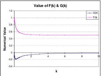
Figure 4.2 Value of G
( )
k and F( )
k vs k ...35Figure 4.3 Aerofoil displacement...42
Figure 4.4 Thrust generation...43
Figure 4.5 Whole-wing heaving...46
Figure 4.6 Root flapping...47
Figure 4.7 Lift coefficient amplitude variation against 1k per unit heave and pitch angle ...53
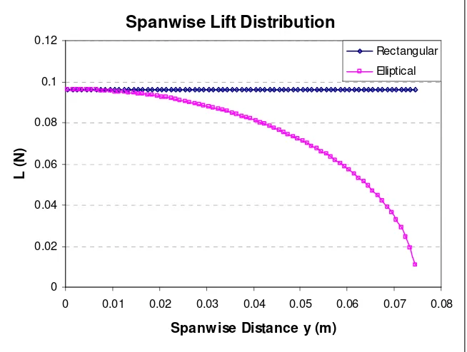
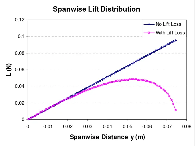
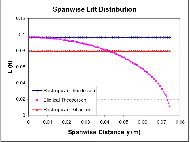
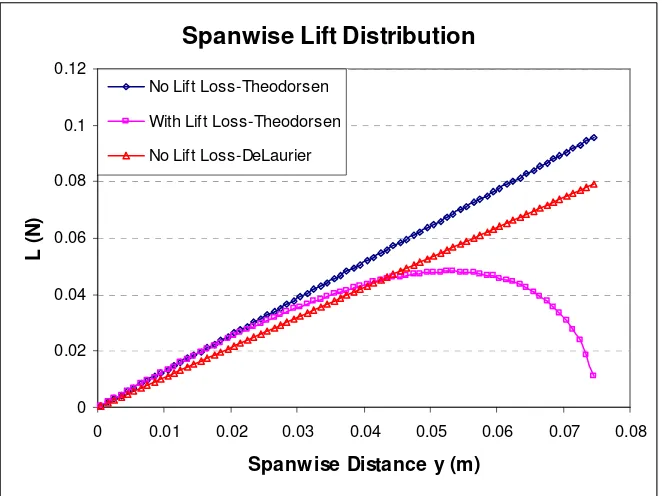
Figure 4.8 Spanwise lift distribution calculated by Theodorsen for whole-wing motion .55 Figure 4.9 Spanwise lift distribution calculated by Theodorsen for root flapping ...56
Figure 4.10 Spanwise lift distribution comparisons for whole-wing motion ...58
Figure 4.11 Spanwise lift distribution comparisons for root flapping ...59
Figure 4.12 Forces due to heaving motion in time history...61
Figure 4.13 Simple harmonic motion of heaving ...61
Figure 4.14 Forces due to pitching motion in time history ...63
Figure 4.16 Heaving and pitching combined motion ...65
Figure 4.17 Combined motion of mode 1...66
Figure 4.18 Combined motion of mode 2...67
Figure 4.19 Combined motion of mode 3...67
Figure 4.20 Combined motion of mode 4...68
Figure 4.21 Propulsive efficiency of heaving motion ...69
Figure 4.22 Energy dissipated in the wake of pitching ...70
Figure 5.1 Wing frame with strain gauge attached at the root...73
Figure 5.2 Gear box design...73
Figure 5.3 Side panel with gear box...74
Figure 5.4 Floor...74
Figure 5.5 Assembled test rig ...75
Figure 5.6 Position sensor...75
Figure 5.7 Beam for displacement test ...75
Figure 5.8 Test rig design for pure heaving motion...76
Figure 5.9 Test rig for pure pitching motion ...77
Figure 5.10 Test rig for heaving and pitching combined motion...78
Figure 5.11 Test section of the T3 wind tunnel ...78
Figure 5.12 Pitot tube ...79
Figure 5.13 Micro-manometer ...80
Figure 5.14 Test data logging set up ...80
Figure 5.15 Spanwise inertia distribution...81
Figure 5.16 Spanwise aerodynamic force...83
Figure 5.17 Relationship between tip load Wc and strain gauge signal in heaving motion ...84
Figure 5.18 Relationship between tip load Wc and strain gauge signal in pitching motion ...84
Figure 5.19 Relationship between tip load Wc and strain gauge signal in combined motion...85
Figure 5.20 Inertia force test...86
Figure 5.22 Heaving motion in wind tunnel test...88
Figure 5.23 Moment due to lift in heaving motion ...88
Figure 5.24 Pitching motion in wind tunnel test...89
Figure 5.25 Moment due to lift in pitching motion...89
Figure 5.26 Combined motion in wind tunnel test...90
Figure 5.27 Moment due to lift in combined motion ...90
Figure 5.28 Inertia force comparison of heaving motion ...91
Figure 5.29 Inertia force of pitching motion...92
Figure 5.30 Inertia force comparison of combined motion ...93
Figure 5.31 Aerodynamic force comparison for heaving motion ...94
Figure 5.32 Test result of heaving motion in time history for 4m/s, 4Hz ...95
Figure 5.33 Computed result of heaving motion in time history for 4m/s, 4Hz...95
Figure 5.34 Aerodynamic force comparison for pitching motion ...96
Figure 5.35 Test result of pitching motion in time history for 4m/s, 4Hz...97
Figure 5.36 Computed result of pitching motion in time history for 4m/s, 4Hz ...97
Figure 5.37 Aerodynamic force comparison for combined motion ...98
Figure 5.38 Test result of combined motion in time history for 4m/s, 4Hz ...99
Figure 5.39 Computed result of combined motion in time history for 4m/s, 4Hz...99
Figure 5.40 Wing configuration... 101
Figure 5.41 Test rig setup ... 102
Figure 5.42 Electrical equipment setup ... 103
Figure 5.43 Data log setup... 103
Figure 5.44 Arrangement of balance calibration ... 104
Figure 5.45 Lift force calibration ... 105
Figure 5.46 Drag force calibration ... 105
Figure 5.47 Lift and drag coefficients of sting with fuselage ... 107
Figure 5.48 Wing frame stiffness calibration ... 108
Figure 5.49 Steady lift coefficient at 0° angle of attack ... 109
Figure 5.50 Steady drag coefficient at 0° angle of attack... 110
Figure 5.51 Inertia test comparison... 111
Figure 5.53 Lift amplitude of flapping wings at 3Hz and 0° angle of attack ... 113
Figure 5.54 Mean horizontal force of flapping wings at 3Hz and 0° angle of attack ... 113
Figure 5.55 Input power of flapping wings at 3Hz and 0° angle of attack... 114
Figure 5.56 Theoretical calculation of flapping motion at 2m/s, 3Hz ... 115
Figure 5.57 Test result of flapping motion of Wing 1 at 2m/s, 3Hz ... 115
Figure 5.58 Test result of flapping motion of Wing 1A at 2m/s, 3Hz ... 116
Figure 5.59 Test result of flapping motion of Wing 1B at 2m/s, 3Hz ... 116
Figure 5.60 Steady loading acting on the flexible wing ... 117
Figure 5.61 Total lift comparison in 0° angle of attack... 118
Figure 5.62 Image of flapping wing upstroke motion... 119
Figure 5.63 Image of flapping wing downstroke motion ... 119
Figure 5.64 Flexible wing performance in flapping motion... 121
Figure 5.65 Theoretical and proposed lift distribution on half span ... 121
Figure 5.66 Flapping flight with wing twist ... 122
Figure 5.67 Combined heaving and pitching flapping wing motion ... 123
Figure 5.68 Twist angle effect ... 125
Figure 6.1 Hang glider comparisons ... 127
Figure 6.2 Hang glider structure ... 130
Figure 6.3 Force and velocity vectors for gliding flight... 131
Figure 6.4 Wills Wing Sport 2-155 hang glider ... 134
Figure 6.5 Wing geometry... 134
Figure 6.6 Comparison of L/D estimates with manufacturer’s data ... 136
Figure 6.7 Lift coefficient versus angle of attack ... 137
Figure 6.8 Drag coefficient versus angle of attack ... 137
Figure 6.9 Lift-to-drag ratio versus angle of attack ... 138
Figure 6.10 Weight effect on minimum sink rate ... 138
Figure 6.11 Sink rate vs angle of attack ... 139
Figure 6.12 n-V diagram ... 141
Figure 6.13 Spanwise lift coefficient distribution... 143
Figure 6.14 Spanwise lift distribution ... 143
Figure 6.16 Shear force diagram at n=1... 146
Figure 6.17 Bending moment diagram at n=1... 146
Figure 6.18 Wing frame construction... 147
Figure 6.19 Schematic drawing of the Wills Wing Sport 2-155 hang glider ... 148
Figure 6.20 Top view of hang glider ... 149
Figure 6.21 Bottom view of hang glider ... 149
Figure 6.22 Front view of hang glider... 150
Figure 6.23 Side view of hang glider ... 150
Figure 6.24 Ornithopter wing frame ... 152
Figure 6.25 Wing frame dimension... 153
Figure 6.26 Location of the hang point and control bar point ... 153
Figure 6.27 Dimension of each section of wing ... 154
Figure 6.28 Isometric view of ornithopter... 155
Figure 6.29 Isometric view of flapping mechanism... 156
Figure 6.30 Motor support frames ... 157
Figure 6.31 Comparison of spanwise lift distribution on semi-span ... 159
Figure 6.32 1:20 scale wing configuration ... 160
Figure 6.33 Test rig setup ... 161
Figure 6.34 Lift force calibration ... 162
Figure 6.35 Drag force calibration ... 163
Figure 6.36 Inertia force comparison ... 164
Figure 6.37 Aerodynamic force comparison ... 165
Figure 6.38 Test result of flapping motion of design case 1 for 4m/s, 2Hz ... 166
Figure 6.39 Theoretical calculation of flapping motion for 4m/s, 2Hz... 166
Figure 6.40 Geometry modelling of hang glider... 167
Figure 6.41 Geometry modelling of hang glider wire... 168
Figure 6.42 Mesh elements of wing surface ... 169
Figure 6.43 Mesh and bar elements of wing frame and boundary condition ... 169
Figure 6.44 Loading case with factor of n=1... 170
Figure 6.45 Stress on the wing skin ... 172
Figure 6.47 Axial stress on the wing frame ... 173
Figure 6.48 Wing deformation... 173
Figure 6.49 Stress on the wing skin (n=7)... 174
Figure 6.50 Stress on the wing frame (n=7) ... 175
Figure 6.51 Axial stress on the wing frame (n=7) ... 175
Figure 6.52 Wing deformation (n=7) ... 176
Figure 6.53 FE modelling of ornithopter... 178
Figure 6.54 Stress on the wing skin in gliding... 179
Figure 6.55 Stress on the wing frame in gliding ... 179
Figure 6.56 Axial stress on the wing frame in gliding ... 180
Figure 6.57 Wing deformation in gliding ... 180
Figure 6.58 Spanwise lift comparison of flapping and gliding... 181
Figure 6.59 Spanwise lift and inertia distribution... 182
Figure 6.60 Stress on the wing skin in flapping... 183
Figure 6.61 Stress on the wing frame in flapping ... 183
Figure 6.62 Axial stress on the wing frame in flapping ... 184
Figure 6.63 Wing deformation in flapping ... 184
Figure 7.1 Design case 1... 189
Figure 7.2 Design case 2... 189
Figure 7.3 Design case 3... 190
Figure 7.4 Design case 4... 190
Figure 7.5 Inertia force comparison ... 191
Figure 7.6 Measured lift amplitudes in downstroke at 0° angle of attack... 192
Figure 7.7 Measured lift amplitudes in upstroke ... 193
Figure 7.8 Drag force comparison of flapping wing... 194
Figure 7.9 Lift amplitude comparison over a cycle (Case 1 & 2)... 195
Figure 7.10 Lift amplitude comparison over a cycle (Case 1 & 3)... 196
Figure 7.11 Lift amplitude comparison over a cycle (Case 1 & 4)... 197
Figure 7.12 Drag comparison of case 1... 198
Figure 7.13 Drag comparison of case 2... 198
Figure 7.15 Drag comparison of case 4... 200
Figure 7.16 Test result of flapping motion of design case 2 for 4m/s, 2Hz ... 201
Figure 7.17 Test result of flapping motion of design case 3 for 4m/s, 2Hz ... 201
Figure 7.18 Test result of flapping motion of design case 4 for 4m/s, 2Hz ... 202
Figure 7.19 Angle of attack of spanwise strip ... 205
Figure 7.20 Wing tip deformation at 2Hz... 205
Figure 7.21 Comparison of modified spanwise lift... 207
Figure 7.22 Stress on the wing skin with modified flapping aerodynamic load ... 208
Figure 7.23 Stress on the wing frame with modified flapping aerodynamic load ... 208
Figure 7.24 Axial stress on the wing frame with modified flapping aerodynamic load . 209 Figure 7.25 Wing deformation subject to modified flapping aerodynamic load ... 209
Figure 7.26 Modified ornithopter wing frame ... 212
Figure 7.27 CATIA model of optimal design of ornithopter... 212
Figure 7.28 CATIA model of fold axis ... 213
Figure 7.29 Outer wing fold control... 214
LIST OF TABLES
Table 3.1 Power functions of wing dimensions and flight parameters against body mass
...23
Table 3.2 Design specification comparisons of two ornithopters...28
Table 3.3 Preliminary design specifications ...31
Table 4.1 Parameters for whole-wing motion ...54
Table 4.2 Parameters used for heaving motion...60
Table 5.1 Specifications of wing sample... 101
Table 5.2 Calibration coefficients ... 106
Table 5.3 Lift and drag forces of sting and fuselage ... 108
Table 5.4 Input and output data ... 112
Table 6.1 Hang glider design specifications... 128
Table 6.2 Speed in different conditions... 133
Table 6.3 Wing design specification ... 135
Table 6.4 Hang glider performance... 139
Table 6.5 Flight speed definition ... 141
Table 6.6 Wing frame dimension... 147
Table 6.7 Estimated weight of ornithopter parts... 151
Table 6.8 Design specification of ornithopter ... 151
Table 6.9 Radne Racket engine... 154
Table 6.10 Tip amplitude and arm length... 155
Table 6.11 Ornithopter wing design specification ... 158
Table 6.12 Calibration coefficients ... 163
Table 6.13 Material properties of 7075-T6 aluminum alloy ... 170
Table 6.14 Material properties of glass fiber ... 171
Table 6.15 Material properties of steel alloy ... 171
Table 6.16 Stress on each layer of the skin ... 171
Table 6.17 FEA results with load factor n=1 and n=7... 176
Table 7.2 FEA results comparison ... 203
Table 7.3 Comparison of FEA results in different loading case... 210
Table 7.4 FEA results comparison in different speed ... 210
Table 7.5 FEA results comparison in different speed ... 211
NOMENCLATURE
c: Wing chord
b: Half of wing chord
s: Wing span
l: Geometric length
S: Wing area
AR: Wing aspect ratio
h: Displacement
α : Pitch angle
a: Pitch axis normalized by half chord
V : Velocity
ρ: Air density
ω: Frequency
f : Flapping frequency
k: Reduced frequency
( )
kC : Complex Theodorsen’s circulatory function
L: Lift
D: Drag
T : Thrust
I : Inertia
W: Weight
Q: Shear force
M : Bending moment
P: Power
ϕ: Phase shift
t: Time
η : Propulsive efficiency
E: Average kinetic energy increase in unit time
c
N : Section’s circulatory normal force
a
N : Apparent mass
l
C : Lift coefficient
d
C : Drag coefficient
φ: Angle
Λ: Wing sweep angle
n: Load factor
c: Geometric mean chord
λ: Taper ratio
ACRONYM
MAV: Micro Air Vehicle
VLA: Very Light Aircraft
CSF: Calibration Scale Factor
AF: Aerodynamic Force
Dis: Displacement
AoA: Angle of Attack
CFC: Carbon Fiber Composite
FEA: Finite Element Analysis
FEM: Finite Element Method
CFD: Computational Fluid Dynamics
1 Introduction
1.1 Research Motives and Objectives
The simultaneous production of aerodynamic lift and propulsion by means of flapping
wings is hardly a new idea. Humans have been intrigued and fascinated by observations
of bird and insect flights for hundreds of years and many of them were inspired to invent
machines that can sustain them in flights. However, it wasn't until the beginning of the
last century when other forms of propulsion were invented, such as propellers followed
by jet engines that human flights had become a reality.
Conventional aerodynamic theory development is mostly based upon studies of fixed
wings in a steady airflow, while the airflow around flapping wings is anything but steady
and challenges our understanding. The success of a man-made flapping-wing flight
vehicle depends greatly upon a full understanding and application of unsteady
aerodynamics, structural stability, vibration and aeroelasticity. In these fields, some
classical theory such as Theodorsen’s theory and more advanced numerical methods such
as Computational Fluid Dynamics (CFD) and Finite Element Method (FEM) have been
well developed and employed for flapping-wing study. However there is a lack of an
efficient and yet accurate approach not just for understanding but also for designing a
successful large scale flapping-wing aircraft. The aim of this project is to develop an
aerodynamic and structural model for a flapping wing ornithopter design and analysis
based on extended use of a classical aerodynamic theory and FEM structural modelling.
The ornithopter is an aircraft heavier than air which flies like a bird by flapping its wings.
The special feature lies in the wings that do not only generate lift but also thrust.
Compared with fixed-wing aircraft, ornithopters have some practical benefits for flight
• Improved Efficiency
An aeroplane propeller is only about 70% efficient. Energy is wasted because
some of the aerodynamic force produced on the blades acts to resist the motion of
the propeller. In an ornithopter, the downstroke wing resistance provides lift, and
during the upstroke the wing can be feathered so resistance is minimized.
Therefore the ornithopter has potentially higher efficiency than an aircraft with
rotating propeller. The jet-engined aircraft has yet to match piston-engined
aircraft in fuel efficiency and due to the complexity of the propulsive system the
weight of the jet engine is dramatically increased with high fuel consumption.
• More Lift
Flapping wings have some additional ways of producing lift and thrust that are
not available with fixed wings or rotating blades. The rotating blades have to be
designed with a fixed angle in order to generate lift and thrust but the flapping
wing can work effectively at different angles relative to the direction of airstream
with unique flexibility to adapt to the flow while flapping. One example of this
adaptability is the clap-fling technique, first discovered in insects. By bringing
together the wings and then abruptly flinging them apart, a powerful burst of
thrust can be produced. Another technique is delayed stall. Flapping wings do not
stall as easily as fixed wings because the cyclical motion does not allow much
time for a stall to develop. In some situations, it might actually be useful to stall
the wing, because the downstroke air resistance is actually a strong lifting force.
These techniques can be used to improve the slow flight and hovering capabilities
of some ornithopter designs.
• High Manoeuvrability
Whereas an aeroplane relies on its forward speed to produce manoeuvring forces,
the flapping wing with suitably adaptable flapping cycle and wing geometry can
produced large manoeuvring forces at any time. The incredible manoeuvrability
of birds is partly due to their small size and partly due to their use of flapping
• Reduced Noise
Aeroplane and helicopters make a lot of noise. Much of the noise is produced by
the high velocity jet flow emitting from the engine casing or the helicopter blades
rotating at high speed. The environmental impact of high noise levels is one of the
many factors preventing the wider use of helicopters.
As demonstrated by birds, flapping wings offer potential advantage in
manoeuvrability and energy saving compared with fixed-wing aircraft, as well as
potentially vertical take-off and landing capabilities. With further development,
ornithopters could offer great fuel economy combined with the manoeuvrability of a
helicopter achievable at greatly reduced or minimal noise impact to the environment.
By exploring these advantages of flapping wing aircraft a great deal of work has been
done recently in studying and experimenting small scale ornithopter flight which is so
called insect flight. However the imitation nature’s flapping-wing flight has been
humanity’s oldest aeronautical dream. History provides numerous examples of human
efforts and attempts trying to achieve that dream by him strapping on wings and
falling from high places. Due to the limitation of knowledge and understanding of
aerodynamic, structures and control techniques required for the design of flapping
flight vehicles people have been trying for a hundred years but not much success has
been achieved.
The objective of this research is to carry out aerodynamic and structural investigation
of flapping wings in simple harmonic oscillations. The aim is to carry out extensive
study of the performance of flapping wings of various configurations and man-made
models in order to gain a thorough understanding to help optimise the wing and
configuration design for a human-controlled ornithopter. The key research scopes are
summarized as follows:
• Flapping wing species investigation
• Theoretical study of unsteady aerodynamics for simple harmonic oscillatory
• Experimental investigation of flapping wings in different oscillatory motions
• Preliminary design of manned ornithopter
• Optimal design of ornithopter
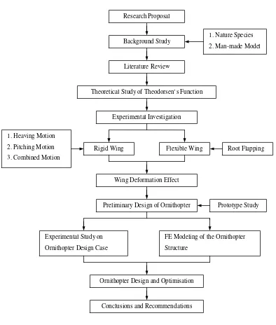
A research flow-chart, giving an overview of the approach used in the present
[image:27.612.101.495.214.678.2]investigation, is given below.
Figure 1.1 Research flowchart
Research Proposal
Background Study
1. Nature Species 2. Man-made Model
Literature Review
Theoretical Study of Theodorsen’s Function
Experimental Investigation
Rigid Wing
Preliminary Design of Ornithopter Flexible Wing
Wing Deformation Effect 1. Heaving Motion
2. Pitching Motion 3. Combined Motion
Root Flapping
Prototype Study
Experimental Study on Ornithopter Design Case
FE Modeling of the Ornithopter Structure
Ornithopter Design and Optimisation
1.2 Flying Species in the Natural World
Studies on flapping wing flight have always been done as an attempt to simulate the
flight of flying animal species, birds in particular. In nature 10,000 types of birds and bats
have been found and attracted scientific attention. The kinematic descriptions of the
flapping motions have been made according to their flapping frequency, weight, wing
span and power requirement.
Birds range in size from 5cm (Bee hummingbird) to 2.75m (Ostrich) and insects are even
smaller and lighter. The flapping frequency of the above species that fly varies from
10Hz to 100Hz and the total weight varies from a few grams to 100kg. In Henk
Tennekes’ book [1] a trend line of weight against cruising speed for most known flying
objects is illustrated in Fig. 1.2. In the left bottom region it indicates the insects with low
weight and speed. In the right top area it shows the man-made aeroplanes with high
weight and speed. The region relating to birds is in the centre of the graph. The objects
above this trend line indicate that in spite of their significantly greater weight, flight can
be sustained by higher cruising speeds. The fliers below this line indicate very low speed
flights can only be sustained with very low body weights. Following the diagram most of
natural flying species with low cruising speed can support even higher body weight
relative to its size by adopting flapping wing motion instead of other forms of propulsion.
Figure 1.2 The relationship between weight, wing loading and cruising speed [1] Insects
1.3 Man-made Aircraft
Man’s urge to fly has been around for as long as he has become an intelligent being and
developed curiosity and fascination about how all things work in nature. The idea comes
from seeing the beauty, grace and freedom of soaring birds. The early concept of flying
machine is to imitate birds by the use of flapping wing which is so called an ornithopter.
Leonardo da Vinci created dozens of sketches of flying machine based on the flapping
wing concept. However all the attempts failed because the flying capabilities of birds
have never been fully understood and replicated by humans. Then another early idea of
aviation attempt is by putting hot air or gas lighter than air in a closed container which is
so called lighter-than-air craft. The most famous airship was built by Zeppelin in 1900.
However the gas used in early days was flammable and the airship was economically
inefficient and operationally unreliable. By copying soaring birds without flapping the
glider was developed in latter part of the nineteenth century which was the first so called
heavier-than-air craft. In 1903 Wright brothers built the first powered aeroplane and
launched flight successfully. After the Wright brothers aeronautical activities took place
in civilizations. During World War I & II aircraft were rapidly developed and evolved
driven by military needs. After World War II fantastic technological advances have been
realised in both military and civil aircraft. The jet engine was rapidly improved to
increase thrust and reduce fuel consumption. Wing sweepback was employed to achieve
supersonic flight.
Following the recent rapid development of aircraft and other unmanned flight vehicles
the early concept of flapping flight is beginning to draw people’s attention again. The
question is as follows: with rapid advances in both knowledge and technologies available
for aircraft design and manufacturing nowadays, can we achieve our original dream of
human-designed and powered flapping flight, mimicking what nature has mastered for
millions of years? To this end, many works have been carried out to investigate and
1.3.1 Micro Air Vehicles
Since the Wright brothers built their biplane in the early twentieth century powered by
man-made engines and propellers, no serious attention has been dedicated to the flapping
wing problem as an alternative way of propulsion. However, the advent of new
technologies and development of Micro Air Vehicles (MAV) capable of flying at low
Reynolds number have given researchers in the last decade impetus to reconsider
flapping wing vehicles as alternative design possibilities. In practice, a lot of effort has
been concentrated in recent years in developing analytical models of a flapping wing to
explain the high lift coefficients that steady state aerodynamics cannot explain. Although
complicate in general, the motion of bird wings can be decomposed in three main
components: plunging, pitching and sweeping. Simplification of this motion should
enable us to investigate forces acting on a wing performing vertical and rotational
displacements. Micro air vehicle is generally defined as a class of aircraft with a
maximum dimension of 6 inches that is capable of operation at flight speeds of
approximately 25mph or less, with mission duration of 20 to 30 minutes.
A number of successful fixed-wing MAV designs have been produced by several
universities, commercial and institutions. As shown in Fig. 1.3 from left to right, they are
Aerovironment’s Black Widow, NLB’s Trochoid, and the University of Florida’s flexible
wing design. The potential application of current fixed-wing MAV designs is limited due
to manoeuvre constraints.
Figure 1.3 Several successful fixed-wing MAVs [2-4]
Numerous MAVs have been proposed for civil and military applications and of which
Vanderbilt’s Elastodynamic Ornithoptic Insect, and UC Berkeley’s Micromechanical
Flapping Insect. These models have been designed and made for both the biological and
engineering studies of natural insect fliers. Microelectronic system is employed to
achieve the flight control and smart material is used in the manufacturing of wing
membrane and driving mechanism.
Figure 1.4 Several ornithoptic MAV concepts [5]
1.3.2 Large Scale Ornithopters
To design, build and fly a large scale ornithopter has been of interests among some keen
aviators and aeronautical engineers for centuries. Ornithopters are mechanical, powered,
flapping-wing aircraft designed and built to imitate the flapping wings and flights of
birds. Some notable developments in flapping wing flight vehicles included the gliding
human-powered ornithopter of Alexander Lippisch in 1929, Percival Spencer’s series of
engine-powered, free-flight models in the 1960s. The most recent major advancement in
flapping wing flight was spawn from the ingenuity and ambition of Jeremy Harris and
James DeLaurier. In 1999, the Harris/DaLaurier engine-powered piloted aircraft was able
to self-accelerate, by flapping wings alone, to lift-off speed, however it has yet to
maintain steady flight. The major problem was the wing could barely provide enough
thrust for unassisted liftoff. In 2006, Yves Pousseau succeeded in flying a
human-muscle-powered ornithopter on his 212th attempt. DeLaurier also had success with an engine-powered ornithopter in 2004. The UTIAS Ornithopter No. 1 made a jet-assisted takeoff
and 14 seconds flight. Later on Delaurier’s Snowbird flight managed to sustain both
The latest two successful ornithopter design cases worthy of detailed studies are the
engine-powered (UTIAS No.1) and human-powered ornithopters (Snowbird) both
developed by DeLaurier as shown in Fig. 1.5. These two existing big scale ornithopters
will be studied in details in Chapter 3 as design case reference.
Figure 1.5 Large scale ornithopters UTIAS 1 and Snowbird [6]
1.4 Thesis Outline
The present thesis consists of eight chapters including the introduction Chapter 1, where
the motivation, research background and main focus and contribution of this research are
outlined.
In Chapter 2 recent research works are reviewed both in the theoretical methods and
practical design cases. Relevant literature publications are studied on analytical and
numerical methods developed for unsteady simple harmonic oscillatory wing motions
and successful design cases of MAVs and large scale ornithopters.
Chapter 3 introduces the methodologies of this research. By investigating natural fliers
and man-made aircraft it is shown that scale effect is one of the key issues which affect
ornithopter design. The design concept of large scale ornithopter is presented in terms of
Chapter 4 reports on the study of unsteady aerodynamics by Theodorsen’s function and
other analytical methods extended from Theodorsen’s theory. Aerodynamic forces in
terms of reduced frequency are investigated for wings undergoing different simple
harmonic oscillations. Theoretical calculations are carried out of aerodynamic forces
acting on the flapping wing with specific parameters to compare with experimental
measurements. Theodorsen’s function is employed for the calculations of rigid and
flexible wings undergoing different simple harmonic motions. Different wing
configurations are also studied in this chapter.
Chapter 5 describes the experimental study of flapping wings of different configurations,
flexibility and flapping motions. Wind tunnel tests are carried out to validate the
theoretical calculations and the wing flexibility effect is studied in detail. The wing
deformation is discussed in relation to the flapping motion and flight orientation.
In Chapter 6 the preliminary ornithopter design is carried out. Hang glider is employed as
a prototype to conduct the wing design. Aerodynamic forces are measured and validated
by theoretical calculations. Finite element modelling is carried out to assess the structural
strength and stiffness of the ornithopter.
Based on the previous investigation the modification and optimisation of the ornithopter
is carried out in Chapter 7. The modified wing structure and control system is described.
Chapter 8 concludes the thesis with a summary of major findings of the research.
2 Literature Review
The following literature survey provides an overview of recent research work and a
summary of their most important findings relevant to the present investigation. The
overview focuses on a number of areas: the theoretical methods in the study of flapping
wing aerodynamics, the study of natural flyers, structural design of flapping wing aircraft,
experimental study of flapping wings.
2.1 Literature Review
2.1.1 Analytical Studies on Flapping Wing
Theodorsen [7] first brought to general attention the problem of flutter in 1934. In his
paper a mathematical model was given subject to the unsteady forces acting on a flat
wing section performing infinitely small oscillations in pitch and plunge in an inviscid
fluid with an undisturbed uniform flow. Expressions for lift and moment were derived
which have been used extensively for the study of unsteady aerodynamics and
aeroelasticity for many years.
However Theodorsen’s function is not able to predict any horizontal force acting on the
aerofoil in the streamwise direction because of the assumptions of inviscid flow
underlying the theory. In 1936 Garrick [8] derived an expression for the horizontal force
of an aerofoil undergoing small oscillations based on Theodorsen’s theory. By
considering the wake’s energy gain during a complete cycle of oscillation he found that
thrust can be generated and it depended upon the frequency and the amplitude of
oscillation of the aerofoil motion. Garrick’s results, which will be described in detail in
Chapter 4 shows that for a pitching aerofoil thrust is obtained only beyond a threshold
frequency, while below this frequency drag is obtained. For a wing undergoing plunge
oscillations a thrust is created regardless of the frequency and in particular the efficiency
The theories from Theodorsen and Garrick are based on the rigid thin aerofoil. In 1953
Spielberg [9] provided a method for studying two-dimensional, incompressible
aerodynamic coefficients associated with harmonic changes in camber. In his study the
flexibility of a thin aerofoil is first taken into account. The derivation makes use of
linearized aerodynamic equations relating the pressure on the profile to the downwash
distribution. From this theory the flexibility of chordwise has a positive effect in the high
lift generation for small oscillations of thin aerofoil.
A design-oriented model for the unsteady aerodynamics of a flapping wing has been
developed using a modified strip theory approach by DeLaurier [10]. In contrast to
Theodorsen’s approach the finite wing planform is taken into account. In particular, an
alternative expression to account for circulatory flow effect due to wing aspect ratio AR
has been proposed (see 4.2.2, Chapter 4).
The analytical method is user friendly in the initial design as a guide. The theory is based
on the thin rigid aerofoil under small simple harmonic oscillation with air flow fully
attached on the wing.
2.1.2 Numerical Studies on Flapping Wing
The limitation of Theodorsen’s theory is that it is valid only for thin aerofoil with small
plunge amplitude and is not suitable for describing the phenomena of large oscillation
due to the large angle of attack.
Numerical method is also widely used to solve aerodynamic force problems in unsteady
flow conditions. When the flow is incompressible, the velocity potential satisfies
Laplace’s equation. For flow over a thin aerofoil, Laplace’s equation is solved subject to
the boundary condition on the aerofoil section with respect to which the flow field is
antisymmetrical. These flow conditions are fulfilled by placing a sheet of continuous
vorticity on the aerofoil surface and its wake. The problem then becomes one of
distribution along the aerofoil surface. S. Guo [11] developed a numerical modelling tool
for predicting the aerodynamic forces on an oscillating aerofoil and the aeroelastic
response of a flexible flapping wing. In his paper comparisons are carried out of results
obtained by using Theodorsen method, deformable wavy wake method, unsteady panel
method and by experimental work.
A group of researchers, in particular K.D. Jones and M.F. Platzer [12-17] employ an
unsteady panel method code for the computation of flapping wing flowfield based on
potential flow theory. In their papers aerodynamic forces in vertical and horizontal
directions are investigated and validated with experimental work. The effect of aerofoil
thickness is also investigated and compared with linear theory. Some important results
are found in particular, the thrust increases with the frequency of oscillation, but the
efficiency decreases because of the unsteady effects of the wake which appears to
confirm Garrick’s findings earlier.
CFD is well developed in recent years for investigation of aerodynamic phenomena.
Although CFD approach should be capable of providing more accurate simulation of the
vorticity and flow unsteadiness for flapping wings, it is usually discarded in the early
design phase of the wing due to its high complexity involving grid generation and huge
computational time.
2.1.3 Flapping Wing Investigation from Nature
Unlike fixed-wing aerodynamics, there have not been any available design rules for
flapping-wing aerodynamics. Two approaches are adopted for this project. One is to learn
from natural flyers and try to understand and replicate their flight performance
characteristics. The other is to study flapping-wing aerodynamics both theoretically and
experimentally in order to improve our understanding and provide data for flapping-wing
vehicle design. A lot of research has been done in the study of flying animals. In T. Nick
Pornsin-sirirak’s report [18] the flying animals are investigated in terms of wing span,
2.1. From this plot the flight of flyers can be separated into two regimes: quasi-steady and
unsteady states. For larger flyers, their flights can be approximated by quasi-steady-state
assumptions because their wings flap at lower frequency during cruising and behave
closely to fixed-wings. On the other hand, smaller birds and insects fly in an
unsteady-state flow regime in which their wingtip speed is faster than their flight speed. For small
flyers the research is focused on the high lift coefficient and high efficiency generation.
In Ellington’s research [19] the insect flapping flight is investigated. Some insects use the
fling mechanism: the wings are clapped together and then flung open before the start of
the downstroke, creating a lift-enhancing vortex around each wing. Most insects,
however, rely on a leading-edge vortex (LEV) created by dynamic stall during flapping; a
strong spanwise flow is also generated by the pressure gradients on the flapping wing,
causing the LEV to spiral out to the wingtip. In Okamoto’s work [20] the aerodynamic
characteristics of the wings and body of a dragonfly and of artificial wing models were
studied by conducting two types of wind tunnel tests and a number of free flight tests of
gliders made using dragonfly wings. The results were consistent between these different
tests. In M. Sato’s research [21] the images of damselflies in free flight in a transparent
container is video-taped and kinematic data used in the calculations obtained by
analyzing the images. In Taylor’s report [22] the propulsive efficiency of animals is
investigated and was found to be related to the Strouhal numberSt which is normally
defined in terms of the characteristic length of the object L and its wing frequency f of the
oscillation and the speed of the airstream V∞asSt= fL V∞. It indicated that propulsive efficiency is high over a narrow range of St and usually peaks within the interval 0.2 < St
< 0.4. Experiments have been done within the interval 0.2 < St < 0.4 and high peak
Figure 2.1 Flight regime of steady-state and unsteady-state of natural flyers
In Wei Shyy’s report [23] a large amount of work has been done by studying the structure
of birds in order to conduct the MAV wing design. In his study a scale factor of wing
span with body mass is given in Fig. 2.2. Relations between characteristic geometry and
flapping motion are obtained by summarizing the performance data of fliers. The
aerodynamic forces and power required under different flapping motions are also
investigated.
2.1.4 Flapping Wing Structural Modelling
By simulating insect flight several flapping wing design cases have been done in recent
years [17], [24-28]. By employing new techniques and advanced materials the wing mass
can be kept rather low and at the same time strong enough. The flapping wing models are
mostly micro air vehicles by simulating insect flyers with limited wing span of 150mm.
In the current design of MAV the system is composed of an electric motor, a transmission
system, and two wings. Powered by the electric battery plunging motion is achieved to
generate lift and propelling force in low speed. In the last several years micro air vehicles
have been well developed in flying performance and power transmission. However there
had been no successful large flapping wing ornithopter available until 2003 when Sandra
Mau [29] first built a large ornithopter with one pilot in Canada. For the large scale wing
the major problem is that the wing can not provide enough lift and thrust even with large
plunging amplitude and steady sustainable flight has never been achieved. In his work a
unique wing was designed for the tests. From the tests, some interesting results were
found. Increasing the spar torsional stiffness would increase both lift and thrust. The
effect of structural stiffness is rather significant for large flapping wing aircraft.
2.1.5 Aeroelastic Effect on Flapping Wing
Subject to the unsteady aerodynamic forces acting on the flapping wing the deformation
of the wing leads to another phenomenon of aeroelasticity. In S.A. Combe’s paper [30]
the aeroelastic effect of the insect wings was investigated. It indicated that the dynamic,
three-dimensional shape of flapping insect wings may influence many aspects of flight
performance. Finite element model was developed to compare with the measured
displacement along the wing in response to a point force. The results suggest that the
sharply declining flexural stiffness measured in real wings helps maintain rigidity near
the wing base, while localizing bending to the tip and trailing edge, which are regions of
particular importance in controlling aerodynamic force production. Experimental work
was carried out by Pin Wu [31] to study the aeroelasticity of flapping wing MAVs. Six
pairs of wings with varying elastic properties are tested for thrust measurement. The aim
2.1.6 Experimental Studies on Flapping Wings
To validate computational results experimental work needs to be carried out in the wind
tunnel or water tunnel. New techniques are employed in the test measurement such as
high speed camera and balance. In recent years the experimental work has mainly
focused on the testing of vortex passing by the wing [11] [32], lift and thrust due to the
wing plunging motion [28] [33], and propulsive efficiency of flapping wing [34]. In
Ebrahimi’s [35] research a flexible membrane wing was developed with 0.8m wing span.
Wind tunnel test were conducted between 6m/s and 12m/s at frequency of 0 to 9Hz.
Averaged thrust and lift were measured at 10° angle of attack. The results were used to
find optimum performance of the flapping wing vehicle. Two wings with 25cm and 74cm
were constructed by Sergey [36] to carry out the study of features of flexible flapping
wings used in micro air vehicles. Lift and thrust generated by the flapping motion were
measured to conduct the study of the required power and propulsive efficiency.
Optimisation of flapping wing kinematics was carried out by Thomson [37] based on
experimental results. Vertical force was measured using a load cell subject to a scaled-up
hawkmoth wing. The test result was used to optimize the trajectory of a flapping wing
mechanism. Jonathan Warkentin [38] designed a tandem wing flapping wing model with
span of 0.72m. Lift and thrust were measured through various angles of attack and
compared with the results from studies of dragonflies. Many experiments [39-41] have
been done to conduct the design and construction of a flapping wing model. Unlike the
test of fixed-wing the output results of flapping wing shows a sinusoidal manner due to
the simple harmonic wing motion. Therefore the accuracy of the test results requires
rather high sensitivity of the test equipment. Most of the experimental work has focused
on the aerodynamic force measurement in terms of total force. The inertia force is
normally ignored which compromises the accuracy of test results. Not many works have
shown the aerodynamic forces in time history with the variation of the wing position.
Furthermore, there appears neither serious attempt nor a proper method has been
developed to filter the raw data. Noise due to vibration is the main problem in affecting
the measured aerodynamic forces. In the wind tunnel test the wing is designed as light as
possible with rigid frame covered with flexible film which is considered as flexible wing.
membranes. By using this kind of design it is not feasible to carry out the test for flexible
effect because the wing frame is rigid and there is not obvious deformation.
2.2 Summary
From the large amount of literature, the current state-of-the-art of flapping wings in
unsteady conditions is studied. By studying and mimicking flyers in nature several
ornithoptic concepts have been attempted. Theoretical solutions are developed to predict
the aerodynamic forces for flapping wing motions. Based on the theory many prototypes
are designed by applying new techniques and advanced materials to optimise the flight
performance. Many works are focused on the aerodynamic forces investigation of
flapping wing micro air vehicles (MAV), in particular with the investigation of different
wing motions. In most recent works that have been done the main method used is
simulating wake vorticities to predict aerodynamic forces in low speed and high
oscillatory frequencies. The method requires large amount of numerical calculations and
complicated test condition to validate.
The objective of this project is to investigate the aerodynamic and structural effects of
flapping wings and develop a plausible large scale ornithopter design. However the main
thrust of this project is not to focus on the aerodynamic forces prediction. Analytical
method is employed in the initial stage of the force calculations such as Theodorsen’s
theory. Wing planform is designed by studying the existing design cases and natural
flyers. Experiment will be carried out in the wind tunnel subject to low air flow speeds
3 Methodology
The research plan and its scientific approaches are represented in this chapter. The aim of
this thesis is to develop a practical design of human-controlled ornithopter. The design
method is shown in Fig. 3.1
Figure 3.1 Research plan of ornithopter design
In order to design such an aircraft that flies by flapping its wing the fundamental
principles of flapping flight need to be studied first aerodynamically and biologically. By
studying the aerodynamic flights of natural flyers trends can be found of the flapping
performance in terms of characteristic dimensions of the flying species. By comparing
existing man-made aircraft the design profile is decided in terms of weight, scale, and
flight conditions. Several types of aircraft are assessed in order to find a suitable baseline
ornithopter design prototype. Detailed studies of flapping wing aerodynamic are carried
out by means of theoretical methods and wind tunnel measurements in order to provide
useful data for ornithopter design and optimisation. The preliminary design is carried out
Natural Flyers Study
Flapping Flight Principles of Flying Species
• Dimension
• Weight
• Flight performance
Prototype Selection
Theoretical Study Experimental Study
Preliminary Design
based on the prototype specifications. Validations and modifications of the design are
based on theoretical and experimental investigations.
3.1 Parametric Study of Flying Species
An ornithopter is defined as a heavier-than-air craft designed to be propelled through the
air by flapping its wings. An effective ornithopter must have wings capable of generating
both thrust, the force that propels the craft forward, and lift, the force perpendicular to the
direction of flight that keeps the craft airborne. These forces must be strong enough to
counter the effects of drag and the weight of the craft. A good understanding of how
these aerodynamic lift and propulsive forces can be achieved simultaneously by flapping
wings is essential for the design and construction of such an aircraft. To this end flying
species of the natural world will be carefully studied.
In studying of birds, it is very helpful to assess the effect of different parameters, such as
wing area, wing span, cruising speed, body weight, and wing loading. Tennekes [1]
presents a diagram of the relationship between weight and wing loading of several birds
as illustrated in Fig. 3.1. A proportional scale relationship between weight and wing
loading of most seabirds is given by
( )
13 W c S W×
= (3.1)
where W is the body weight, S is wing area and c is a constant.
Figure 3.2 The relation between weight and wing loading for some seabirds[1]
Due to the geometrical similarity of birds recent studies have been attempted to find
relations between parameters connected to bird flight and some of these are given in
Table 3.1. However the equations do not always give correct predictions as stated in
particular it has been found that in many cases the relation between wing loading and
mass increases slower than that indicated in Table 3.1.
Animal group Wing span
(m)
Wing area
(m2)
Wing loading
(N/m2)
Aspect ratio
All birds except
humming-birds
Humming-birds
1.17M0.39
2.24M0.53
0.16M0.72
0.69M1.04
62.2M0.28
14.3M-0.04
8.56M0.06
7.28M0.02
Table 3.1 Power functions of wing dimensions and flight parameters against body mass
M
By flapping their wings the flying species are able to maintain airborne in low speed
because of their low weight and therefore low wing loading. The main function of the
wing is to transmit a force to external environment during flight. For flapping wings
flyers, the flapping frequency turns out to be an important parameter in both lift and
thrust generation and therefore against body mass. Norberg [43] summarized the various
trends of wing beat frequency against body mass of a wide range of natural flyers as
shown in Fig. 3.3. For hummingbirds the trend clearly locates in a region of high flapping
frequency and light weight. With an increasing body mass the wing beat frequency is
reducing significantly. The trends exposed by these researches are that larger animals
tend to oscillate their wings at lower frequencies than smaller ones. For all birds an
estimation of wing beat frequency related to body mass is given by
33 . 0
87 .
3 −
= M
Figure 3.3 Wing beat frequency in birds [43]
3.2 How Birds Fly
The mechanics and aerodynamics of bird flight have intrigued people for many centuries.
Birds have many physical features that work together to enable them to fly efficiently
such as light weight, smooth feathers, enlarged breastbone, light bones, rigid skeleton,
and a streamline body. Above all these advantages the bird possesses the most important
of its body’s component is the wing. The shape of a bird’s wing is critical for producing
lift and its curvature allows the air to move faster over the top surface relative to the
lower. Also the angle of the wing deflects air downwards, causing a reaction force in the
opposite direction and therefore creating lift.
The performance of bird flight is studied in gliding, soaring and flapping. When a bird is
gliding, it doesn’t have to do any work. The wings are spread out to the side of the body
but do not flap, maintaining at a slight angle to generate lift. The bird has to dive slightly
to maintain forward speed. Soaring flight is a special kind of glide in which the bird flies
in a rising column of air which is so called a thermal. Due to this rising air the bird can
maintain or even gain height without flapping its wings. Therefore the gliding and
soaring can be seen as steady flight without any movement of wings. In flapping the
bird’s wing flaps with an up-and-down motion. The entire wing span has to flap at the
![Figure 3.2 The relation between weight and wing loading for some seabirds[1]](https://thumb-us.123doks.com/thumbv2/123dok_us/1561104.108728/45.612.136.476.74.573/figure-relation-weight-wing-loading-seabirds.webp)
![Figure 3.4 Wing twist over a stroke [44]](https://thumb-us.123doks.com/thumbv2/123dok_us/1561104.108728/49.612.102.512.74.320/figure-wing-twist-over-a-stroke.webp)
![Figure 3.5 Force vector on the take-off mode and cruising mode [44]](https://thumb-us.123doks.com/thumbv2/123dok_us/1561104.108728/50.612.104.514.76.349/figure-force-vector-mode-cruising-mode.webp)