1
Time to reflect: a strategy for reducing risk in structural design
Iain A MacLeod
Professor Emeritus, University of Strathclyde
Introduction
The use of computers has resulted in immensely beneficial changes both, at the operational level of doing design and at the conceptual level of making us think more carefully about the processes that we use and how they should be used.
However there is much disquiet about the risks involved in their use. Hazards, that may lead to faults including disasters include:
When relying on software, engineers’ control of the design process is diminished. Much of the process may be automated requiring little input from the user. Designers become deskilled. Their understanding of design contexts is reduced.
There is misplaced confidence in the potential of the software to produce outcomes that will be fit for purpose.
Innovation will be stifled.
A main strategy for guarding against such risk is to use what is called the reflective approach1. This implies that one adopts a degree of scepticism about all received and generated information; one is open to ideas; one poses and seeks answers to questions; one makes personal assessments and reassessments and seeks advice from others, especially from experts; second or more opinions are sought if appropriate; when faults are found or improvements can be made, action is taken; an appropriate amount of resource is allocated to seek to ensure reliable outcomes.
Use of reflective thinking is fundamental to good engineering practice. Computer use does not diminish the need for it.
Cases
Two cases of failures that illustrate the risks and the potential role of reflective thinking in avoiding them are dicussed.
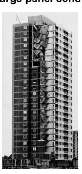
Large panel construction for buildings
In the 1960s, structural designers in the UK used Code of Practice CP 114
Design of Reinforced Concrete Buildings for the technical assessment of
large panel buildings. Many of these designers did not ask the question: “Does CP114 address all the issues that need to be considered for the design of large panel buildings that are constructed using precast wall and floor panels?” The answer to that question was a resounding “No”. CP114 was written mainly for cast in situ beam and column structures; important issues for large panel buildings, particularly about how the panels should be connected, were not addressed in the code and hence in many, if not most, of the designs.
[image:1.595.79.164.509.690.2]Consequences of this lack of reflective thinking included: Figure 1 The failed
2
A major structural failure causing 4 deaths (The Ronan Point Collapse). High cost of retrofitting existing buildings that were found to be unsafe.
Long term pause in the use of a construction method that has advantages for some types of building.
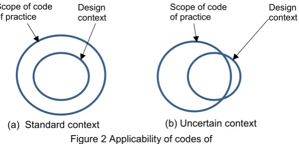
In Figure 2, a ‘standard context’ can be considered as one with which the design team is wholly familiar and there is no innovation; codes of practice fully apply. An ‘uncertain context’ is one which involves any degree of innovation and/or issues that are unfamiliar to the design team. Safety-critical situations are also in the uncertain domain. The designers of large panel buildings in the 1960s did not realise that they were working in a context exemplified by Figure 2(b). They were not asking the right questions.
The Sleipner Platform Collapse
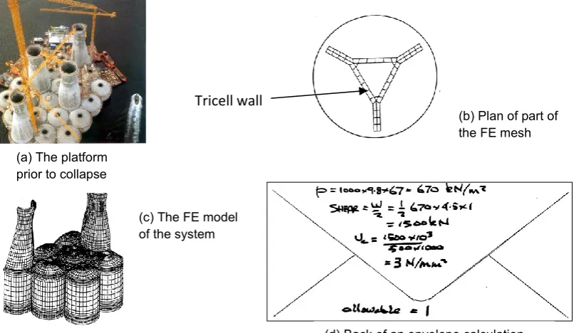
In 1991 a large concrete oil recovery platform - Figure 3(a) - was close to completion in a Norwegian Fjord when a loud bang was heard and the structure sank to the sea floor – a total loss. The fault was traced to shear failure in a ‘tricell’ wall - Figure 3(b) - at a the bottom of the structure. The system had been modelled using 3D finite elements (FE) - Figure 3(c) - the results from which were used for assessment of the shear strength of the wall. Questions that could/should have been asked include:
Is the model that I am using more complex than is appropriate? The designers of the Slepiner
Platform assumed that that because they were using a complex model that it would necessarily give adequate predictions. In the case of the tricell wall, bending theory would have resulted in much better predictions of bending moment and shear force than from the model used. Is the mesh of elements used adequate for the purpose? A review of the FE mesh in the area
that triggered the collapse - Figure 3(c) - by a person experienced in FE modelling could have prompted an investigation of the accuracy of the mesh for predicting bending actions. Can I do a simple check calculation? Figure 3(d) shows a calculation, on the back of an
envelope, based on treating a 1m depth of the tricell wall as a beam withstanding a 67m hydrostatic pressure head. The predicted shear is 3 times the allowable.
The consequence of failing to ask and respond to such questions was a financial loss of over $700m (a) Standard context
Scope of code
of practice Design context
Scope of code
of practice Design context
[image:2.595.96.399.147.293.2](b) Uncertain context context
3
The Design Process
At its most basic level, the design process includes the following activities/stages:
Inception Where information about the context is gathered and the requirements are
established.
Conception Where a set of conceptual designs/options are identified and assessed against the
requirements leading to a decision about the design solution
Production Where the information needed to create the entity is established.
Review This is the reflective activity that is pervasive in the process
In structural engineering this process can be applied to the structural system as a whole or to a part or to details.
While the process may be mainly linear as shown in Figure 1, it can be deeply iterative, e.g. in product design, a prototype may be manufactured, tested, modified, re-tested and so on.
Traditionally 'structural design' meant the use of code of practice rules to ensure that the system and its parts would perform satisfactorily. The term is now used for the process of synthesising and assessing the whole of the design information for a structure. It is better to refer to assessment using codes etc. as technical assessment. Technical assessment is sometimes required at the concept design stage to assess options but it is mainly used in the production stage of design.
It is said that if bad decisions are made at the concept stage, no amount of good detailing can rescue the situation. The need for reflective thinking at all stages of the design process is therefore
Figure 3 The Sleipner Platform collapse
(b) Plan of part of the FE mesh
(d) Back of an envelope calculation (a) The platform
prior to collapse
(c) The FE model of the system
Tricell wall
Inception Conception Production
[image:3.595.78.481.77.311.2]Review
4
evident. However it is errors in technical assessment that have the greatest potential to result in major failures/disasters. Therefore this area is of the greatest concern in seeking to ensure that computer use is satisfactory.
Technical Assessment
Main processes in technical assessment are:
Model development process Here the ‘model’ is the set of rules that need to be addressed
(normally code of practice rules). The main reflective question at the model development stage is “Have all the relevant issues been addressed and are the rules used adequate for this
purpose?” This is the validation question. In standard design contexts not much resource needs to be applied to model development but with innovation, posing the validation question is a key issue. It was here that the designers of large panel buildings in the 1960s made their main errors. The fault that caused the collapse of the Sleipner Platform lay in the decision about what
analysis model to use.
Solution Process i.e. doing the calculations. Reflective questions here include: Is the software
reliable?’ ‘Are the input values correct?’
Output assessment Here the main reflective question is: “Has the model been correctly
[image:4.595.72.384.424.637.2]implemented?” This is the verification question.
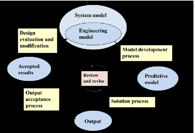
Figure 5 is a diagram of the predictive modelling process. Technical assessment rules are predictive in the sense that they are used to assess future performance of the structure. In this diagram the rectangular boxes are sub-processes and the oval boxes can be considered to be states. The system model is the full set of information about the entity being designed. The engineering model is that part of the system model that requires technical assessment.
Figure 5 The modelling process
5
Analysis modelling
The analysis model is the mathematical representation of the behaviour of the structure. The
analysis modelling process1,2,3,4 has the same form as illustrated for technical assessment in Figure 5. It is a sub process of technical assessment. The validation question is: “Is the analysis model capable of satisfying the requirements?”
In traditional engineering education, analysis modelling, i.e. structural analysis, was treated as a dominant issue. Students learned to do time consuming calculations by hand. Now engineers do not do complex hand calculations. Some people are of the opinion that this results in a decline in understanding of behaviour but the accuracy and efficiency of computer processing means that complex hand calculations are in the past. We must therefore look to other sources for
understanding of structural behaviour. Computer use is seen as the problem; in reality it is the solution. Responding to reflective questions using analysis software can significantly enhance understanding of behaviour.
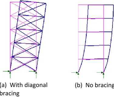
For example suppose, if you were accustomed to analysing braced frames for buildings you may observe that a frame of this type, under uniformly distributed lateral load, tends to deflect as in Figure 6(a). Then you solve for a similar, but moment resisting, frame with no diagonal bracing and find that the lateral deflection is as in Figure 6(b). A natural reaction is to think that you have made an error. To respond to this reflective question, you do some experimentation by varying the stiffnesses of the members of the frame. This leads to the conclusion that there is a fundamental difference in how the two types of frame resist lateral load. You find out what characterises the difference. Your learning about behaviour improves significantly. Using such knowledge then informs improvement in design decisions.
People say that in modern practice there is little time for such reflection. But if a structural designer is operating outside the standard envelope (Figure 2(b)), the risk in not being reflective is unacceptable.
Structural Failures
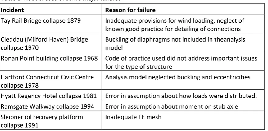
[image:5.595.97.285.443.603.2]While the scope of what we define as structural design is, as it should be, much wider than in the past , the risk of failure is still a dominant issues. The track record for preventing major failures in the UK is very good but the risk will always be present. Reflective thinking is a key strategy in controlling such risk. Table 1 lists seven major failures and their root causes. None of the causes listed are related to errors in doing the calculations. The faults all occurred at the model development stage of design; in each case the validation question was not properly addressed. Very few major failures
Figure 6 Lateral displacement of frames (a) With diagonal
bracing
6
[image:6.595.71.503.122.333.2]are attributable to errors of the doing calculations. This does not mean that errors in calculations are not made nor that improvements in methods for identifying them should not be sought.
Table 1 Root causes of some major failures
Incident Reason for failure
Tay Rail Bridge collapse 1879 Inadequate provisions for wind loading, neglect of known good practice for detailing of connections Cleddau (Milford Haven) Bridge
collapse 1970
Buckling of diaphragms not included in theanalysis model
Ronan Point building collapse 1968 Code of practice used did not address important issues for the type of structure
Hartford Connecticut Civic Centre collapse 1978
Analysis model neglected buckling and eccentricities Hyatt Regency Hotel collapse 1981 Error in assumption about how loads were distributed. Ramsgate Walkway collapse 1994 Error in assumption about moment on stub axle Sleipner oil recovery platform
collapse 1991
Inadequate FE mesh
While we are very aware that structural calculations need to be carefully checked, the lesson to be learned from Table 1 and other major failures is that all the sub-processes of the modelling process (Figure 5) need to be assessed in a reflective way.
BIM
Building Information Modelling (BIM) is leading to automation in structural design. More
importantly, it is an enabling technology for interdisciplinary working. A fundamental aim is that each design discipline will be able to access the models of the other disciplines involved (BIM 2) or that all parties will access a central model (BIM 3). In doing this, difficulties must arise, for example, in controlling revisions to the design. The brain has special ability to make associations and identify anomalies that is not replicable by software. While seeking to use software in managing the processes, the brain must continue to be used as a main source for controlling uncertainty. The same reflective ethos as outlined in this paper needs to be applied to all processes whether or not the work is in a BIM environment. BIM software must be such that it is possible for designers to get answers to questions such as “What assumptions were made for the analysis model?“ “What is the deflected shape?” “ What is the bending moment diagram for that beam?”
Conclusion
A computer can do calculations and repeat them much more efficiently and accurately than is possible using brain power. Computer power also beats brain power at processing logic especially when the rule set is complex.
On the other hand, the deep associativity of knowledge and other features of the brain allows us to: identify patterns, make subtle inferences, understand, have hunches, ask penetrating questions, generate ideas, etc. Computer technology is a long way from replicating the phenomenal power of the brain to ‘think’.
If a process can be defined as a formal algorithm, to implement it on a
7
would have been possible that the software used for the Sleipner Platform model (Figure 5) had an embedded rule that flagged up the fault that led to the collapse – but harnessing the thinking ability of the brain must remain a central activity in the design process. This should work in partnership with formal quality management systems – as discussed in the paper on page xx
The low incidence of major structural failures in the UK indicates that we do have good checks and balances to prevent them. But the key strategy of reflective thinking, that is at the core of good engineering practice and is very important in controlling risk, tends not to be explicitly addressed in education and training. Failure of structures is, of course, just one of the risks that need to be controlled by such thinking.
I believe that that the ethos in which one operates, i.e. the thought processes that guide our thinking and actions5,6, is as important as technical knowledge in the pursuit of successful engineering outcomes.
Structural engineers who have not developed a reflective ethos in their work must seek to move in this direction. In education, teachers must seek to instil a reflective ethos in student project work.
References
1. MacLeod I A and Weir A, The principles for computer analysis of structures. Institution of Structural Engineers
2. IStructE: Guidelines for the Use of Computers for Engineering Calculations, Institution of Structural Engineers, 2002, ISBN: 0 901 297 20 8
3. Macleod, I. A.: Modern Structural Analysis – Modelling Process and Guidance, 2005, Thomas Telford Ltd, ISBN: 0 7277 3279 X
4. Borthwick, A, Carpenter J, Clarke B, Falconer R and Wicks J, The importance of understanding computer analyses in civil engineering, Proceedings ICE, Volume 166 Issue 3, August 2013, pp. 137-143
5. MacLeod I A, The Ethos of professional engineering, Journal IESIS, Paper1665, Volume 154, pp7-12, 2014
Available at: http://www.library.iesis.org/2014/IESIS-trans154-paper1665.pdf
6. Lucas B, Harrison J and Claxton G Thinking like an engineer, Implications for the education
system Report, Royal Academy of Engineering may 2014. Available at: