AN HIERARCHICAL APPROACH TO HULL FORM DESIGN
Marcus Bole and B S Lee
Department of Naval Architecture and Marine Engineering, Universities of Glasgow and Strathclyde, Glasgow, UK
1 ABSTRACT
As ship design tools become more integrated and more advanced analysis tools are introduced, the ability to rapidly develop and modify hull forms becomes essential. Modern hull design applications give an experienced user the ability to create almost any shape of hull. However, the direct manipulation of hull surface representations is laborious and may limit the exploration of design concept to the fullest extent. Transformation of parent forms and parametric hull generation tools can provide a quick solution, but neither method is conducive for innovative design.
2 INTRODUCTION
Ship designers are always seeking to improve their designs to maintain a competitive edge in the market place. Those that show that they can consistently develop practical, efficient and safe vessels, which can be designed and built cheaply, will tend to lead the development of ship design. To meet the growing needs of the design process, a wider range of complex tools are being increasingly used to analyse a range of performance criteria, from the performance of the hull form using CFD software to the safe design of the arrangement with evacuation simulations.
To meet the growing trend of the use of numerical analysis tools, CAD systems have had to adapt to these new design strategies by providing a solution that allows the product to be easily optimised using the results of the studies. Rapid design techniques have been introduced into other areas of engineering, particularly where there is a large amount of repetitive tasks or the product is complex in structure. These tools aid the designer by providing the features that are most likely to be used, based on the current state of the design. The development of the product can then progress much quicker. Most tools dealing with simple geometry can be improved easily and some even provide an environment that integrates with the analysis tools. However, hull surface design tools have developed little since the introduction of free form surfaces in the 1970’s and have yet to provide a practical solution that provides the designer with an effective way of quickly developing hull forms and allowing optimisation using analysis data. Today, the design of hull surfaces can be separated into the three distinct techniques: design from a parent hull; manual creation of a new hull surface and parametric hull generation.
3 DESIGN FROM A PARENT HULL FORM
The use of a parent hull surface to derive a new design has been the traditional approach adopted by naval architects particularly in the shipyard. It is an effective way of producing a new design from an existing vessel of which the performance is known. Consequently, the risk of the new vessel performing below expectations should be quite low as long as the new design does not deviate greatly from the basis hull. The initial work of developing a good hull form will not be necessary and, if the vessel is similar to the parent design, most of the detailed work should be valid also. Subsequently, design costs will be kept low.
While transformations are an effective means of quickly modifying a hull surface, the global nature means that subtle distortions can be introduced in the particular features of the surface or appendages. Consequently, this method offers no real functionality for improving hydrodynamic performance apart from simple modification, such as lengthening operations. The resulting design produced by transformation will always remain characteristically similar to the original hull form.
4 DIRECT MANIPULATION OF THE HULL SURFACE
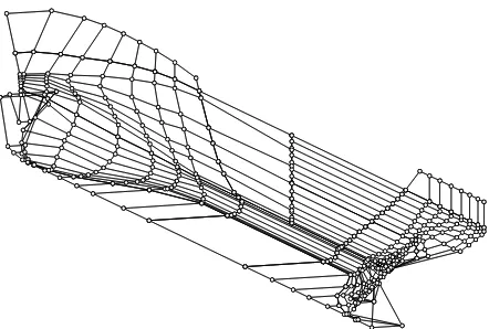
[image:3.612.210.431.370.519.2]If a basis hull surface is unavailable, the designer will have to develop a new representation using any of the many hull design systems available today. The definition process usually consists of the interactive creation and manipulation of geometric elements using the mouse (Figure 4.1). The designer will generally manipulate control curves through which surfaces will be interpolated or will manipulate the surface representation directly. NURBS have become the most common mathematical representation for representing hull surface geometry. NURBS are popular because the technique is relatively easy to implement in software and it is not necessary to develop any complex editing tools for good results to be obtained. Furthermore, NURBS are the de-facto standard for transferring surface information between CAD systems.
Figure 4.1 The control polygon of a hull represented by several NURBS surfaces. Each vertex is manipulated using the mouse to modify surface shape.
introduction of higher-level functions that could be used to reduce the amount of unnecessary surface manipulation of definition are greatly desired.
5 PARAMETRIC HULL DESIGN
[image:4.612.170.469.231.339.2]Parametric hull design has always been seen as an answer to the tedious process of manually creating a new hull form surface. The objective of these methods is to use numerical parameters to drive mathematical functions that generate a hull surface. As the hull surface has all the properties specified by the initial numerical parameters, there is no need to modify the surface further.
Figure 5.1 A parametric yacht hull form developed by YachtLINES [2].
Parametric hull generation tools have changed very little since introduction. The hull surface is generated from curve functions that have been developed using a set of numerical parameters. Often the curve functions will represent the shape of form parameters such as the waterline breadth or the section area curve, which vary longitudinally over the hull surface. More recently, alternative parametric approaches have been introduced which modify or generate certain elements of the hull definition, such as the template functions in Napa [3] and ShipGEN [4].
6 INTEGRATION OF DIRECT MANIPULATION AND PARAMETRIC GENERATION
While there is a great variety of tools and methodologies used for developing a hull surface representation, the foundation of modern techniques is based in two different and presently incompatible approaches. Direct manipulation is favoured by designers as it provides the flexibility to control the hull surface down to a very detailed level, despite the amount of labour required, and the parametric approach is used where there is a significant amount of concept design work concentrating on high level requirements of the vessel. However, in all cases of design there are usually reasonable amounts of both concept and detailed development and as the design process begins to be dominated by higher level performance characteristics, such as safety and environmental impact, design tools need to adapt to support these new requirements. If we can find a way of integrating the direct manipulation and the parametric approach, the development of the hull form surface representation does not put a large constraint on the design process as a whole.
Potential solutions to the problems faced by the designer when using present methodologies can be found by considering how to integrate the best elements from each methodology. One of the keys to this is to create an environment that caters for the requirements of flexibility at all stages of the design process. In addition, it will be necessary to ensure that any new technique is compatible with current approaches that designers are familiar with and allows us to make the best use of the every growing availability of computing power.
Parametric Hull
Generation ÎConcept Design Initial Design Detailed DesignÎ Î
Parametric Definition
Geometric Definition
Existing Hull Design Tools
Figure 6.1 By integrating parametric and geometric definition, a flexible approach to hull design would result in a development tool capable of adapting
to the design process.
parameters is impractical. Conversely, in the case of hull surfaces developed using the direct approach, it is the control of measurable dimensions that results in the laborious manipulation of the definition.
Based on these factors, the potential improvements to existing hull design techniques should be achieved by closely integrating both techniques together, geometric definition controlling shape and numerical parameters controlling dimensions (Figure 6.1). Furthermore, the balance between the amount geometric and numerical control should be variable to address the requirements in all stages between the conceptual and detailed design phases, to the extent of allowing the hull form surface to be fully parametrically or geometrically controlled as desired.
The integration of parametric and geometric approach is not new and has been a long time goal of developers working in this area. The major limitation in the traditional approach is that the hull surface representation is generated by a mathematical formulation controlled by numerical parameters (Figure 6.2a). In order to allow some geometric control of the surface the mathematical formulations should adapt to all direct manipulations by the user. In practice, it is unlikely, however, that the implementation of such an approach would be robust enough to be used in commercial design.
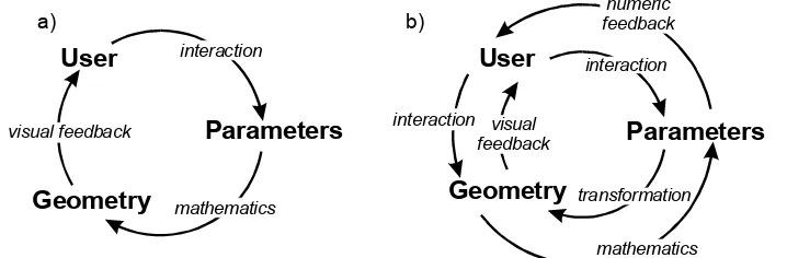
[image:6.612.145.504.343.461.2]Geometry Parameters User interaction mathematics visual feedback a) Geometry Parameters User interaction transformation visual feedback numeric feedback mathematics interaction b)
Figure 6.2 (a) Traditional approach to parametric hull generation (b) A potential solution, integrating the parametric and geometric hull surface
design approaches.
An obvious alternative is to avoid an approach where the surface is defined by numerical parameters via mathematical formulation. In fact, by directly reversing the traditional approach there is potential for a very practical solution (Figure 6.2b). Firstly, the numerical parameters are defined by interrogating the geometrical hull surface representation, which are updated when the design is manipulated directly. Secondly, specific transformations can be introduced that modify the hull surface definition, when certain numerical parameters are edited in the design environment. Consequently, a more apt definition of this approach is parametric modification.
7 INTRODUCING HIERARCHICAL APPROACH TO DEFINING THE HULL REPRESENTATION
Traditionally in design, the hull surface (most likely due to the nature of its construction) has always been considered a single element. Although hydrodynamic characteristics of the surface require that the physical nature must be smooth and fair, in may other areas the hull is divided into smaller manageable parts to make handling easier – in modular construction for example. However, despite the fact that modern ship hull forms have many specific characteristics, the maintenance of the representation as a single entity is kept sacrosanct. Consequently, in the fairing process in particular, much manual effort is used in making sure all the key characteristics continually fit perfectly. Given that many of the criteria for maintaining the relationships between each characteristic could be handled automatically by the hull design tool, design tools have yet to take advantage of any assistance the computer itself could bring to the design environment.
One of the major problems when beginning a new hull surface design using present tools is the requirement to supply a lot of information just to create a reasonable first representation and this is prevalent in both the parametric and direct manipulation approaches. In the case of hull generation the designer will need to supply information on the minimum number of parameters required by the formulation. In the geometric approach, the designer may need to define a representation that potentially has to support all the features that may be introduced to reduce the need for a lengthy restructure of the surface definition later in the design process. In both of these cases, the fact that the hull form is defined as a single homogenous element, due to the nature of the mathematical surface representation, prevents designers breaking the problem down into manageable parts.
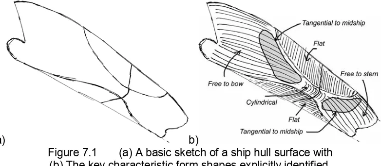
[image:7.612.124.515.456.627.2]a) b)
Figure 7.1 (a) A basic sketch of a ship hull surface with (b) The key characteristic form shapes explicitly identified.
of the design with other lines (Figure 7.1a). Even to somebody with even a modicum of maritime experience the sketch represents a ship hull form. Furthermore, based on the similarities between certain types of hull form it is possible to indicate descriptions of the type of surface characteristics in particular areas of the hull form (Figure 7.1b). Moreover, some of these characteristics have some interdependence that could be used as a basis to form a hierarchical definition structure. For example, the midship section curve defines the prism on which the flat of side/bottom curves lie and the flat of side/bottom curves define surfaces which are planar. Some tools, such as Napa, which uses networks of definition curves for forming hull surfaces, already allow the designer to represent these shapes. However, there has yet to be a tool that takes full advantage of the topological information within the structure to feed into the subsequent definition process.
8 DEVELOPING A DESIGN TOOL BASED ON A HIERARCHICAL DEFINITION APPROACH
The main aim of introducing a hierarchy into hull form definition is to link individual definition elements to others reducing the amount of redundant information. Consequently, during modification any related elements will update to the changes applied. Some techniques such as Relational Geometry have similar aims. However, as these approaches are designed to be generic with many different types of relational tools, they fail to capture the relationships appropriate for hull surfaces. In fact, this study found that it was only necessary to introduce five vertex and three curve relationships for hull surface definition/generation. These relationships are termed ‘constraints’ as they are applied to limit the amount of flexibility of an individual definition element according to the hierarchical definition structure.
The hierarchical definition structure provides an adequate framework for integrating direct manipulation and the parametric modification as discussed in Section 6. In the case of direct manipulation, any changes propagate through the definition structure to update all related elements. The important numerical form parameters can be identified based on the topology of the hierarchical definition structure. Subsequently, specific transformations can be developed which only modify certain definition elements based on the particular numerical parameter changed. As with direct manipulation, changes to transformed elements with propagate through the definition.
Knowledge of common hull form definition structures or topologies could be used to assist the designer in the definition process. The design tool could review the definition provided by the designer, identify missing elements and automatically generate to complete the required structure. This would be extremely useful in the initial stages as the designer would not have to supply all of the definition and the tool could use simple geometric rules or use database information in the generation process. Once the design has reached a stage where the user supplied definition was sufficient the technique would no longer need to control the hull form and the tool would behave much like existing systems.
9 DEVELOPMENT OF A PILOT SYSTEM
In order to demonstrate the feasibility of the concept, a pilot system, named
IntelliHull [5], was developed to address the key aspect of integrating parametric and direct manipulation through the use of hierarchical definition. For simplicity, the tool implements a single surface hull representation using transverse master curves as the primary definition elements. Constraints can be applied to user-defined curves to form specific shapes. The tool interrogates the definition to identify and automatically generate any missing definition curves using the supplied information as a basis for the topology of the hull form. The initial hull surface representation is produced using a longitudinal blending process between definition curves. Subsequently, a parametric bulb can be introduced using warping process.
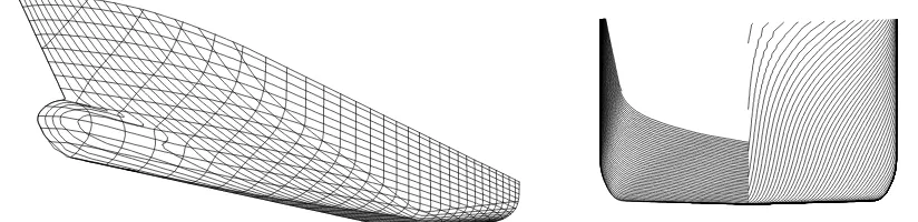
[image:9.612.114.526.480.580.2]The tool identifies eleven form design parameters covering overall and major dimensions plus hydrostatic characteristics and introduces a corresponding transformation for each. IntelliHull is integrated into the PolyCAD [6] design environment and Figure 9.1 shows some examples of hull forms that can be rapidly generated by this technique.
Figure 9.1 Examples of hull forms generated by IntelliHull.
10 CONCLUDING REMARKS
definition into smaller, simpler parts, design tools can be developed capable of adapting more flexibly to the design process. As a result, the long-term goals of integrating direct manipulation of definition and parametric control can be realised in a practical and robust manner through this method. Furthermore, the representation of hull form topology within the technique allows design tools to review the definition and assist the designer by generating the additional definition required to produce a correct surface. The pilot system demonstrates that even a relatively basic implementation is capable of powerful results in a short space of user time.
11 REFERENCES
[1] Lackenby, H. : On the Systematic Geometrical Variation of Ship Forms, Trans. RINA, Vol 92, 1950.
[2] Bole, M. : Parametric Generation of Yacht Hulls, Final Year Project, University of Strathclyde, Glasgow, 1997.
[3] Napa Oy : Napa, http://www.napa.fi/
[4] DEFCAR Ingenieros : ShipGen, S.L, Spain. http://www.defcar.es/
[5] Bole, M. : “A Hull Surface Generation Technique Based on a Form Topology and Geometric Constraint Approach”, PhD Thesis, University of Strathclyde, Glasgow, 2002.
![Figure 5.1 A parametric yacht hull form developed by YachtLINES [2].](https://thumb-us.123doks.com/thumbv2/123dok_us/1727629.126183/4.612.170.469.231.339/figure-parametric-yacht-hull-form-developed-yachtlines.webp)