The Java System Dependence Graph
Neil Walkinshaw
24th April 2003
Technical Report: EFoCS-46-2003
Department of Computer and Information Science
University of Strathclyde
Livingstone Tower
Glasgow, G1 1XH
Abstract The Program Dependence Graph was introduced by Ottenstein and Ottenstein in 1984 [14]. It was suggested to be a suitable internal pro-gram representation for monolithic propro-grams, for the purpose of carrying out certain software engi-neering operations such as slicing and the
compu-tation of program metrics. Since then, Horwitz et
al. have introduced the multi-procedural
equiva-lentSystem Dependence Graph[9]. Many authors
have proposed object-oriented dependence graph construction approaches [11, 10, 20, 12]. Every ap-proach provides its own benefits, some of which are language specific. This paper is based on Java and combines the most important benefits from a range
of approaches. The result is aJava System
Depen-dence Graph, which summarises the key benefits
of-fered by different approaches and adapts them (if necessary) to the Java language.
1
Introduction
Analysing and representing software in terms of its internal dependencies is important for a vari-ety of software engineering applications. These in-clude operations such as slicing and the computa-tion of program metrics. The program dependence graph represents these dependencies, where vertices are program elements and edges represent depen-dencies between them [14]. There have been sev-eral approaches to building graphs for different pro-gramming paradigms and languages. The Java Sys-tem Dependence Graph (JSDG) summarises aspects of object-oriented programming that previous work
has focused on and presents a practical approach to its construction.
Ottenstein and Ottenstein first suggested that de-pendence graphs could be used for software engi-neering operations in 1984 [14]. They proposed a graph which was capable of representing a program consisting of a single block of sequentially executed code. To enable the application of these operations
to multi-procedural programs, Horwitzet al.
intro-duced theSystem Dependence Graph, which
repre-sents every procedure as an individual dependence graph. The procedure dependence graphs are linked to a central dependence graph, which represents the main program [9].
There have been several proposed modifications to the system dependence graph, attempting to en-able the representation of object-oriented programs. Such approaches must be able to cope with prop-erties such as polymorphism, dynamic binding and inheritance. Larsen and Harrold proposed a graph capable of representing these features for C++
pro-grams [11]. This was modified by Kovács et al.
and Zhao, to enable the representation of Java-specific features such as interfaces, packages and single inheritance [10, 20]. Liang and Harrold also augmented Larsen and Harrold’s graph to distin-guish data members in parameter objects, eliminat-ing superfluous dependencies at callsites and hence increasing the accuracy of graph-based operations [12].
construc-2 THE JSDG
tion from a practical perspective and provides an example which demonstrates that the approach pre-sented is viable. Although dependence analysis is an established area, the JSDG enables static anal-ysis to be carried out on a graph which will pro-duce more accurate results than other static Java de-pendence graphs, because it can represent abstract classes which need not necessarily be interfaces and it can distinguish data members in parameter ob-jects.
The next section introduces the JSDG by pre-senting its individual components. Examples of var-ious concepts which are included in the graph are taken from a single larger program which is given in the appendix. This is useful, because it puts the various individual illustrations into context. Section three analyses the graph from a more practical per-spective. It identifies the steps needed for the con-struction of the graph. Section four analyses poten-tial research areas that could benefit from the graph and introduces some practical problems that could arise if the represented program contains features such as threads and exceptions. Section five pro-vides a conclusion and summary.
2
The JSDG
The abbreviation ‘JSDG’ is the same as the abbre-viation used by Zhao [20]. The difference is, that
Zhao’s ‘JSDG’ stands for ‘Java Software
Depen-dence Graph’, and the ‘JSDG’ in this paper stands
for ‘JavaSystemDependence Graph’. This can be
seen as an extension to Zhao’s JSDG, where a dif-ferent mechanism is implemented for dealing with polymorphism and the representation of abstract classes is extended beyond interfaces.
A JSDG is a multigraph which maps out
con-trol and data dependencies1between the statements
of a Java program. Statements are categorised ac-cording to whether they contribute to the structure of a program (i.e. they are headers representing methods, classes, interfaces and packages) or the program’s behaviour (i.e. they belong to a method body). Each category is represented differently on the graph. When these different graphs are com-bined, they provide a graph-based program repre-sentation, which is suitable as a basis for a range of software engineering applications.
The dependence graph is a complex construct and is intended as an internal program representa-tion, not a visual one. It is difficult to visualise a
graph which is composed of such a large number of different types of nodes and edges. This can how-ever be partially facilitated by interpreting the JSDG as a layered architecture, where certain vertices on one layer are visible only to adjacent layers [16].
Depending on the application the dependence graph is intended for, not all of the nodes and edge types are required. The complexity of the graph can be reduced depending on the context in which it is applied. For example, if we intend to slice the de-pendence graph, any nodes or edges concerned with Java interfaces can be omitted.
2.1
A Language-specific
Representa-tion
Object-oriented representations proposed by Larsen and Harrold and Liang and Harrold [11, 12] gen-erate the dependence graph from C++. Several of the differences between C++ and Java require dif-ferent edges or nodes in the graph. Its construction relies on the fact that it is possible to perform some preliminary control, data and call flow analysis on a given Java program, in order to build a skeletal ver-sion of the graph. Given that this framework is es-tablished, other nodes relating to the program struc-ture (e.g. method and class vertices) are added. The accuracy of any traversal algorithm which operates on the JSDG (e.g. a slicing algorithm) depends on the accuracy of the flow analysis performed in the preprocessing stage.
2.2
Statements
A statement represents the lowest layer in the JSDG. It is an atomic construct representing a single
ex-pression in the source code of the program. A
statement representing a call to another method (a
callsite) requires a special representation and is
de-scribed in section 2.4.1. Livadas and Croll suggest that accuracy of a slice on a dependence graph could be improved by increasing the granularity of the SDG to parse-tree level [13].
Java provides a more intuitive way to subdi-vide statements; when a Java program is com-piled, it is translated into an intermediate,
platform-independant format called thebytecode. There are
several bytecode manipulation and analysis tools
1A control dependence
2 THE JSDG 2.3 Method Dependence Graph
available (e.g. Soot2 and BCEL3), which would
make data and control flow analysis between indi-vidual bytecode instructions possible. For the sake of illustration, we will only consider the source-code statement level construction of the graph.
2.3
Method Dependence Graph
Themethod dependence graph (MDG)represents a
single method or procedure in a program. It is the next layer up from the statement layer. MDGs are represented similarly in most OO dependence graph
approaches [10, 11, 12, 20]. Themethod entry
ver-texis connected to any other vertices belonging to
the method viacontrol dependenceedges.
Parameter passing is modelled by introducing
actual andformal variables. On the calling side,
actual-in and actual-out vertices are tagged to copy each variable to and from its temporary location as required. The called method contains formal-in and formal-out vertices, which copy parameter variables from and to these temporary locations respectively.
Parameter-inedges connect actual-in and formal-in
vertices, whileparameter-outedges connect
formal-out and actual-formal-out vertices.
Further formal vertices are connected to the method entry vertex to account for instance vari-ables which may be referenced or modified during the execution of the method. All formal vertices are connected to the method entry vertex and all ac-tual vertices are connected to the callsite via con-trol dependence edges. The flow of data within a method, to its actual-in and formal-out vertices and from its actual-out and formal-in vertices, is
indi-cated by data dependence edges. The call
depen-dence edge indicates the link between the callsite
and the method being called.
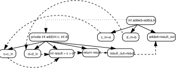
Figure 1 illustrates an example of a simple method which adds two integers. To put this
ex-ample into context, see the call from nodeC23 to
E26 in appendix C. The method is represented by
a method entry vertex (private int add(int c, int
d)), which is connected to statement vertices (int
result = c + d and return result) and
formal-in and formal-out vertices (c=c_in, d=d_in and
result_out=result) via control dependence edges
(plain arrows). The callsite (int added=add(a,b))
belongs to another method and is connected to its
actual-in and actual-out vertices (c_in=a, d_in=b
and added=result_out) via control dependence edges. The call dependence edge from the callsite
to the method entry vertex is represented by a dotted arrow. The actual-in vertices are connected to the formal-in vertices via parameter-in edges (dashed lines). The formal-out vertex is connected to the actual-out vertex via a parameter-out edge (dashed line). Data dependencies within the method (e.g. fromc=c_intoint result = c + d) are represented
bydata dependenceedges (dashed lines). A full
leg-end for all of the examples featured in this paper is provided in appendix A.
c=c_in d=d_in
d_in=b c_in=a
int result = c + d return result result_out=result
added=result_out int added=add(a,b)
[image:3.595.320.500.253.323.2]private int add(int c, int d)
Figure 1: Example of a simple method call
(ex-tracted from appendix - call from nodeC26toE29)
2.4
Class Dependence Graph
Theclass dependence graph (ClDG)represents the
classes in a program [11]. It is the next layer up from the MDG layer. For every class, there exists a
class entry vertex, which is connected to the method
entry vertices of its methods viaclass membership
edges. These membership edges can be tagged as
either public, protected or package (default) to indi-cate their visibility [10]. If one class inherits from
another, they are linked by aclass dependenceedge.
The class entry vertex is connected to its data
mem-bers viadata memberedges.
Figure 2 shows the ClDG of classes
Simple-CalcandAdvancedCalc(see appendix B). Inher-itance is indicated by the class dependence edge
which passes between them. Note that although
Ad-vancedCalcinherits all of the data members and
methods belonging to SimpleCalc (apart from its
constructors), it only needs to be linked to its own specific data members and methods. Inherited data members and methods can simply be computed by traversing up the class dependence edge and along
the class membership / data member edges of
Sim-pleCalc[10].
2 THE JSDG 2.4 Class Dependence Graph
private int add(int c, int d)
public int getA() public int getB()
public int average() private int divide(int c) public int multiply(int c, int d)
public class AdvancedCalc extends SimpleCalc
public int multiply() public class SimpleCalc implements Calculator
public AdvancedCalc() public AdvancedCalc(int aIn, int bIn) public power()
public SimpleCalc(int aIn, bIn) public SimpleCalc()
[image:4.595.95.288.108.194.2]a b
Figure 2: The ClDGs of theSimpleCalc and
Ad-vancedCalc classes from appendix B (see nodes
CE17andCE46)
2.4.1 Object Representation and Polymor-phism
The JSDG represents different instances of a class individually; this enables dependence graph opera-tions such as slicing to take individual objects into
consideration [12]. A statement vertexvwhich
ref-erences an object is expanded into a tree depending
on the context in which vis used. The examples
(figures 3-6) are taken from the calculator example given in appendices B and C. The following four sections illustrate these possible expansions:
1. v is a parameter vertex representing a
stati-cally typed4object:vis expanded into a tree.
Figure 3 illustrates the callsite for getStats(e), given that it can only accept objects of the typeAdvancedCalc.
computePower(e)
a b
AdvancedCalc e
Figure 3: Example of single-typed parameter object
(see nodeC9in appendix)
2. vis a parameter vertex representing a
dynam-ically typed5object:vis connected to a child
vertex for each possible object type and ex-pands each child vertex into a tree containing data members belonging to that object. In
fig-ure 4, e can either be of typesSimpleCalcor
AdvancedCalc.
a b a
SimpleCalc e
b getStats(e)
[image:4.595.361.456.109.215.2]AdvancedCalc
Figure 4: Example of polymorphic parameter object
(see nodeC11in appendix)
3. v is a callsite vertex and the method being
called is defined in a statically typed object: Because the implementation of the method can be determined statically, the callsite can simply be expanded by adding the actual-in and actual-out vertices. Note that, although the method does not have any parameters, we still need to represent the object data mem-bers as actual-in vertices, because they repre-sent the instance variables referenced by the
method. Figure 5 illustrates a call topower()
contained in the statically typed
Advanced-Calcobject.
a b A1_out AdvancedCalc.power
e.power()
Figure 5: Example of a call to a method in a single-typed object (A1_out is the actual-out vertex ) (see
nodeC16ain appendix)
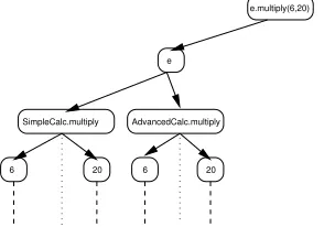
4. v is a callsite vertex and the method being
called is defined in a dynamically typed
ob-ject: vpoints to a vertex representing the
ob-ject defining the method being called. This is further expanded into a tree where the branches represent the candidate types. These are further expanded to reveal the actual-in and actual-out vertices for the (potentially dif-ferent) method implementations and linked to the method entry vertices via call edges. In
2 THE JSDG 2.5 Interface Dependence Graph
figure 6, themultiply()implementation in
Ad-vancedCalcis different to the one in
Simple-Calc. The Java interpreter can only
dynami-cally determine which implementation to ex-ecute.
20 SimpleCalc.multiply
e
20 6
AdvancedCalc.multiply
6
[image:5.595.122.269.182.285.2]e.multiply(6,20)
Figure 6: Example of a call to a method in a
poly-morphic object (see nodeS12ain appendix)
In every case, an object is expanded to reveal its data type(s). These are further expanded to repre-sent their respective data members. If a data member happens to be another object, this must further be expanded to reveal its type(s) etc. This can become problematic if the object is defined recursively. To
address this issue, Liang and Harrold employ
k-limiting(the tree is only expanded to a levelk) [12].
2.5
Interface Dependence Graph
Interface Calculator
public int average()
d=d_in c=c_in
int getB() int getA()
public int multiply(int c, int d)
private int divide(int c) private int add(int c, int d)
public int average() public SimpleCalc(int a, int b) public SimpleCalc()
public int multiply(int c, int d)
int c int d
SimpleCalc implements Calculator
result_out=result int
Figure 7: The InDG (see nodeIE43in appendix)
The Java interface has been represented by both
Kovácset al. and Zhao [10, 20]. Its role is to
spec-ify the signatures of the methods which must be im-plemented by any object implementing the interface.
Neither approach considers the representation of ab-stract classes which are not interfaces. The JSDG represents abstract classes as well as interfaces by treating the interface as a special kind of abstract class.
The JSDG deviates from previous interface rep-resentations by treating the interface as a special kind of abstract class. Because abstract classes can contain method implementations, the use of callsites to represent abstract methods as proposed by Zhao [20] becomes unsuitable. Abstract methods are rep-resented in the JSDG with method entry vertices.
Both Kovács et al. and Zhao omit parameter-out
vertices from abstract method declarations [10, 20]. To fully represent a method signature, if a method returns a value (i.e. is not void), the JSDG connects the method entry vertex to a parameter-out vertex.
The interface dependence graph (InDG)
con-sists of an interface entry vertex which is
con-nected to a set of method entry vertices
represent-ing its abstract methods viaabstract memberedges.
The method entry vertices are connected to param-eter vertices, which represent their input
parame-ters6. Each method entry vertex is connected to the
method entry vertex of the method implementing it
by an implement abstract methodedge. If a class
implements an interface, the class is connected to
the interface by animplementsedge. If a classC1
extends classC2, andC2 implements an interface,
C1 will automatically implement that interface as
well.C1does not to be connected to the interface by
animplementededge, as this is implicit in the
inher-itance hierarchy. Figure 7 illustrates theCalculator
InDG, which is connected to theSimpleCalcclass.
Themultiply(int c, int d)vertex has been expanded to reveal its formal vertices in order to illustrate how parameters from the interface are connected to their implementation counterparts.
Abstract Classes An abstract method contains only the method signature and leaves its implemen-tation to a subclass. If a class contains an abstract
method, it must itself be declared abstract.
Ab-stract classes cannot be instantiated. In C++ the
equivalent effect is achieved by including apure
vir-tual method7 in the class. Because interfaces are
themselves abstract, abstract classes are represented in a similar fashion. The interface entry vertex is replaced with a class entry vertex. The class en-try vertex is connected to abstract methods via an
[image:5.595.88.297.489.636.2]3 CONSTRUCTING THE GRAPH 2.6 Package Dependence Graph
abstract member edge. Abstract methods are
con-nected to their implementations viaimplement
ab-stract methodedges, as they would be in an
inter-face. Non-abstract methods are represented as they would be in a normal ClDG. If a class entry vertex has at least one abstract member edge, it is an ab-stract class.
Absence of Virtual Methods In C++, the inheri-tance structure is slightly more complicated than in Java. Methods which can be overridden and dynam-ically bound at run-time must be explicitly marked
as ‘virtual’. In Java, it is simply presumed that
any derived class which contains a method with the same signature as a method in a superclass overrides all definitions further up the inheritance hierarchy. Because Liang and Harrold base their dependence graph on C++, they require a more complex inheri-tance structure [12]. Because Java allows only sin-gle inheritance and does not feature virtual methods, the JSDG can adopt a simpler inheritance structure, where derived classes can simply reuse base-class method definitions [10] (its simplicity is illustrated in figure 2).
2.6
Package Dependence Graph
A package defines a collection of classes which are conceptually similar or are dedicated to a similar
purpose. It is represented by apackage dependence
graph (PaDG)[10, 20]. Packages are important in
terms of slicing, because they are needed to
accu-rately compute variable visibility. Apackage entry
vertex represents the package, which is connected to each class and interface entry vertex belonging to
the package via apackage memberedge.
3
Constructing the Graph
Ultimately, a Java System Dependence Graph (JSDG) must satisfy the following properties: It must
Represent methods, classes, and packages [10, 20]
Represent abstract methods / classes and in-terfaces
Represent individual objects (it must be able to correctly represent polymorphic parame-ters calls to polymorphic objects) [12]
Represent single inheritance (class hierarchy) [10]
The JSDG pools together the benefits of several
previous dependence graph approaches. It
pro-vides a new representation for interfaces and ab-stract classes and combines the single-inheritance
representation presented by Kovácset al. with the
representation for methods, classes and packages
proposed by Kovácset al. and Zhao [10, 20]. It
also represents individual objects and can distin-guish data members in parameter objects [12]. The pre-processing stage is beyond the scope of this doc-ument, but some important features are discussed briefly. The graph construction proceeds as follows:
1. Construct MDGs
(a) Pre process each method to ascertain callsites
(b) Expand objects
(c) Build data dependencies for data mem-bers
(d) Connect MDG nodes to a class node
2. Construct ClDG
3. Construct InDG
4. Construct PaDG
Pre-processing the Java program Building the JSDG requires prior control and data flow analysis. As discussed in section 2.1, this stage is instrumen-tal in ensuring that the resulting JSDG and any op-erations on it are as accurate as possible. Chambers
et al. propose an approach for accurately analysing
data dependencies in Java programs which can han-dle exceptions, synchronization and memory
con-sistency [3]. Tonella et al. propose a context
and flow-insensitive Points-To Analysis (PTA) ap-proach, which can reduce the size of the initial graph to increase the accuracy of operations such as
slic-ing [18]. Groveet al. propose an approach to elicit
call-graphs for OO programs [5].
A practical approach to carry out this prior anal-ysis would be to use the Soot analanal-ysis framework, which provides several packages to analyse the Java byte-code. A problem with using Soot for this pur-pose is that it operates on the Java byte-code, not the source code. One line of source code usually
con-stitutes several individual byte-code instructions8.
3 CONSTRUCTING THE GRAPH
This is made more difficult by the fact that if a class file is to be used in Soot, it has to be converted into one of several intermediate Soot formats (i.e. Baf, Jimple or Grimp), further confusing the mapping between intermediate instructions and source code line numbers. The upside of analysing a program at a byte-code level is that more precise results can be produced, especially in the case of slicing, where it is usually desirable to obtain a slice which is as accurate as possible.
1. Construct MDGs
1. (a) Processing Callsites In order to determine how the methods communicate with each other, each method must be processed individually. Meth-ods to be processed are identified by traversing the call graph. Once a callsite has been identified it can be expanded (ref. 2.4.1). Once this is done, the
call dependenceedge is followed to determine the
called method, where the appropriate formal-in and formal-out vertices are connected to its entry ver-tex. Conforming to Liang and Harrold’s approach, we only add parameter vertices for parameters and
global variables in the callee’sGREFandGMOD9.
A data dependence exists between verticesAand
BifA modifies / defines a variable which is
refer-enced / used byB. To compute the data
dependen-cies introduced by an object’s data members, Liang
and Harrold only associate theuseof an object with
a callsite if the called method is not a construction.
An objectdefinitionis associated with a call vertex
if the called method is not a destruction. In Java, destructors do not exist. In C++, every object is de-stroyed when it goes out of scope or a pointer vari-able is deleted. In Java, unused objects are automat-ically destroyed in order to free up memory by way of a garbage collector. Java’s closest equivalent of
the destructor is thefinalize()method10. Hence, an
objectdefinitionis associated with a call vertex if it
is not afinalize()method.
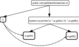
1.(b) Expand Objects In order to expand ob-jects, Liang and Harrold introduce the notion of
an object-flow subgraph. This is a subgraph in
the data dependence graph of a method, contain-ing only the vertices that reference a given
ob-ject. This subgraph is traversed, and each vertex
v is expanded as discussed in section 2.4.1. In
thegetStats(SimpleCalc e) method given in
fig-ure 8, the vertices e, e.getA() and e.getB()
be-long to the object-flow subgraph and hence are ex-panded. [Note that it is necessary to expand the
System.out.println...statement, because it is com-posed of two method calls, which must be repre-sented separately.]
public void getStats(SimpleCalc e)
System.out.println("a: "+e.getA()+"b: "+e.getB())
[image:7.595.341.476.231.312.2]e.getA() e.getB() e
Figure 8: Example of an object-flow subgraph (ver-tices belonging to the graph are in bold)
1.(c) Build Data Dependencies for Data Members
Once object vertices have been expanded, data de-pendencies must be established for the individual
object data members. For a callsitecin a subgraph,
thedefinitionsetDEF(c)of data members consists
of c’s actual-out vertices. The use set USE(c) is
consists of c’s actual-in vertices. If the call
state-ment carries a parameter object, the object’s data
members must be added to theDEF andUSEsets.
For a parameter object, if the vertex defines the
ob-ject11, the object’s data members are added to the
DEF set. Similarly, if the vertex uses the object,
the data members are added to theUSEset. Having
computed theDEF andUSE sets, it is possible to
generate the def-use chains as data dependencies.
2. Construct ClDG It is assumed that the class hierarchy is calculated as part of the pre-processing stage. For every class, a class entry vertex is gener-ated, which is connected to the method entry ver-tices of methods belonging to that class via class
membership edges. Kovácset al. use this
connec-tion to determine the visibility of the method within the class [10]. We adopt this approach as well, so that every class membership edge is tagged as either
9GMOD(m)is the set of non-local variables which can be modified within a methodmandGREF(m)is the set of non-local variables which can be referenced [1].
10In C++, objects are explicitly destroyed as soon as they are out of scope. In Java, they are marked as unused when there are no longer any non-garbage references pointing to them. There is no way of guaranteeing when the garbage collector runs and when
thefinalize()is run. The timing of the garbage collection is also implementation-dependent, i.e. when thefinalize()method is run
depends in part on the Java implementation being used.
4 OPERATING ON THE JSDG
public,private, orprotected. If a class A extends a
class B, A is connected to B via a class dependence edge. By connecting the classes in this manner, Java’s single inheritance structure is emphasised. If a class contains an abstract method (i.e. the class is abstract), it is still represented by a conventional class entry vertex, but is connected to the abstract
method via anabstract member edge. The abstract
method is connected to its implementation in a
sub-class via animplement abstract methodedge.
3. Construct InDG For every interface, there ex-ists an interface entry vertex. This is connected to method entry vertices representing the abstract methods in the interface. These are each connected to their set of formal-in vertices. Each method is connected to its respective implementation’s method
entry vertex via an implements abstract method
edge. The formal-in vertices connected to the inter-face method entry vertices are connected to their im-plementation counterparts via parameter-in edges.
4. Construct PaDG The PaDG is represented by
a package entry vertex, which is connected to its
class entry vertices and interface entry vertices via
packageedges. It is possible for a program to
con-sist of package hierarchies. In this case, subpack-ages are connected to superpacksubpack-ages via package dependence edges. This is an important feature for multi-package programs, because it enables the ac-curate calculation of the visibility of classes.
4
Operating on the JSDG
Although this paper focuses on the graph itself, it makes sense to give the reader an idea of some of its potential benefits. The main application is slicing, which has been the focus of the majority of depen-dence graph based papers [9, 10, 11, 12, 14, 20]. In addition to slicing, Horwitz and Reps also pro-pose that dependence graphs can be used to establish
differences between two programs (program
differ-encing) and to integrate changes carried out on one
program into another similar program (program
in-tegration) [8]. The combination of data and control
dependencies provides a useful basis for the calcula-tion of program metrics [14]. It would also be inter-esting to investigate the usefulness of the JSDG with respect to software inspections. In object-oriented software inspections, delocalised software artifacts which are connected by control and data dependen-cies hamper code reviews, because the code
inspec-tor is forced to jump from one part of the code to another [4].
4.1
Slicing
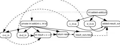
If the JSDG is to be sliced, it needs an additional
edge called the summary edge. These represent
the transitive flow of dependence across a callsite caused by both control and data dependencies. Such an edge connects an actual-in vertex to an actual-out vertex if the value associated with the actual-in ver-tex may affect the value associated with the actual-out vertex. Figure 10 shows the same callsite ex-ample as figure 1, but adds transitive dependencies fromc_in=atoadded=result_outandd_in=b to
added=result_out.
c=c_in
int added=add(a,b)
private int add(int c, int d)
d=d_in
d_in=b c_in=a
int result = c + d return result result_out=result
[image:8.595.307.516.322.405.2]added=result_out
Figure 9: Example of method call with transitive edges between actual-in and actual-out vertices
The slicing algorithm proposed by Horwitz et
al. is split into two phases. The first phase
tra-verses backwards along control, call, parameter in and data dependence edges marking every graph vertex it passes. In the second pass, the algorithm traverses back from each marked vertex along con-trol, parameter out and data dependence edges [9]. Liang and Harrold extended this algorithm to enable the slicing of individual objects [12]. An example
of a slice according to the Horwitzet al.method is
marked out in appendix C (shaded vertices belong to a slice taken from statement S25).
4.2
Program Metrics
REFERENCES 4.3 Software Inspections
It would be interesting to expand on Weiser’s original investigations into slicing based metrics [19]. Bieman and Ott propose the use of program slices to measure functional cohesion [2]. Accord-ing to Riel, a good object-oriented designer strives
for “tight cohesion within classes and loose
cou-pling between classes”[15]. It would be useful to
extend this measure to the object-oriented paradigm. The JSDG provides the basic representation for the computation of these slices.
4.3
Software Inspections
Dunsmore et al. state that delocalised software
artifacts hamper object oriented code inspections
[4]. Software artifacts become delocalised
be-cause object-oriented paradigm features such as in-heritance, polymorphism and dynamic binding can cause code which is responsible for the execution of a single task to be dispersed throughout the pro-gram. These dispersed artifacts are all connected via some form of dependence (or chain of depen-dencies), which can be traced on the JSDG. Slicing could be used to statically determine possible paths of execution in the program, providing the inspector with a reading strategy for the inspection.
“Program understanding requires tracing
chains of method invocations up and down the class
hierarchy”[4]. The inspector must be able to
ab-stract the high level function of a software module to verify that it conforms to its specification. Harman
et al. propose a framework for combining slicing
and concept assignment [6], which would signifi-cantly reduce this laborious aspect of inspections. Further research is required if this approach is to be made practical for object-oriented systems. The JSDG provides a useful basis for investigating the feasibility of extracting Executable Concept Slices (ECSs) for object-oriented programs.
4.4
Practical Issues
The graph has not been designed to incorporate
ex-ceptions and threads. Sinhaet al. represent
excep-tions by adding vertices and edges around the try
and catch clauses of an exception[17]. Hatcliff et
al.study the slicing of multi-threaded programs, but
do not specifically relate their solution to a program dependence graph representation [7].
Another problem that is prevalent amongst most static analysis techniques is that the graph produced is very substantial. This is due to the fact that a static approach must lay out every possible execution that could possibly be carried out by the program. The
size can make the generation and storage of such a graph an expensive process. Depending on the pur-pose for which it is intended certain edges and ver-tices can be removed if they are not going to be used (i.e. interface related vertices and edges can be re-moved if the graph is only needed for slicing opera-tions). If we are only interested in a given subset of methods in the program other parts could be sliced away.
5
Conclusions
This dependence graph provides a useful basis for the representation of Java programs. It enables sev-eral useful software engineering operations to be carried out as queries / manipulations on the graph, which offers greater speed and precision than
con-ventional methods (Horwitzet al. illustrate the
in-crease in precision when slicing the SDG as opposed to Weiser’s conventional algorithm [9]). It provides a representation for interfaces and abstract classes and enables objects and object data members to be treated individually in any operation (e.g. the pro-gram can be sliced object by object). Now, it is pos-sible to re-interpret the dependence graph applica-tions as suggested by Ottenstein and Ottenstein and
Horwitzet al. in terms of the OO paradigm.
Sev-eral potential research areas concerning the JSDG have been proposed. The next logical step in mak-ing the JSDG a practical software engineermak-ing tool is to develop a tool which will automatically build an internal representation of a given Java program.
References
[1] J. Banning. An efficient way to find the side effects of procedure calls and the aliases of variables. InConference Record of the Sixth Annual ACM Symposium on Principles of Programming Languages, pages 29–41, January 1979. [2] J. Bieman and L. Ott. Measuring functional cohesion.IEEE
Transactions on Software Engineering, 20(8):644–658, Au-gust 1994.
[3] C. Chambers, I. Pechtchanski, V. Sarkar, M. Serrano, and H. Srinivasan. Dependence analysis for java. InWorkshop on Compilers for Parallel Computing, La Jolla, LA, August 1999.
[4] A. Dunsmore, M. Roper, and M. Wood. Object-oriented inspection in the face of delocalisation. InProceedings of the 22nd International Conference on Software Engineer-ing, Limerick, 2000.
[5] D. Grove, G. DeFouw, J. Dean, and C. Chambers. Call graph construction in object-oriented languages. In OOP-SLA ’97 Conference Proceedings, 1997.
as-A LEGEND
signment. In9th IEEE Conference on Reverse Engineering (WCRE ’02), Richmond, Virginia, USA, 2002.
[7] J. Hatcliff, J. Corbett, M. Dwyer, S. Sokolowski, and H. Zheng. A formal study of slicing for multi-threaded pro-grams with jvm concurrency primitives. Technical Report 99-6, Kansas State University, March 1999.
[8] S. Horwitz and T. Reps. The use of program dependence graphs in software engineering. InProceedings of the 14th International Conference on Software Engineering, 1992. [9] S. Horwitz, T. Reps, and D. Binkley. Interprocedural slicing
using dependence graphs. ACM Transactions on Program-ming Languages and Systems, 12(1):26–60, January 1990. [10] G. Kovacs, F. Magyar, and T. Gyimothy. Static slicing
of java programs. Technical Report TR-96-108, Research Group on Artificial Intelligence, Hungarian Academy of Sciences, Joesf Attila University, 1996.
[11] L. Larsen and M. Harrold. Slicing object oriented software. In18th International Conference on Software Engineering, pages 495–505, March 1996.
[12] D. Liang and M. Harrold. Slicing objects using system dependence graphs. International Conference on Software Maintenance, pages 358–367, November 1998.
[13] P. Livadas and S. Croll. Program slicing. 1992.
[14] K. Ottenstein and L. Ottenstein. The program dependence graph in a software development environment. In
Proceed-ings of the ACM SIGSOFT/SIGPLAN Software Engineer-ing Symposium on Practical Software Development Envi-ronments, pages 177–184, 1984.
[15] A. Riel.Object-Oriented Design Heuristics. Addison Wes-ley, 1996.
[16] M. Shaw.Pattern Languages of Program Design 2, chapter Some Patterns for Software Architectures. Addison Wesley, 1996.
[17] S. Sinha, M. Harrold, and G. Rothermel. System-dependence-graph-based slicing of programs with arbitrary interprocedural control flow. InProceedings of the 21st International Conference on Software Engineering, May 1999.
[18] P. Tonella, G. Antoniol, R. Fuitem, and E. Merlo. Flow insensitive C++ pointers and polymorphism analysis and its application to slicing.19th International Conference on Software Engineering, pages 433–443, May 1997. [19] M. Weiser. Program slicing. InProc. 5th Int. Conference
on Software Engineering, pages 439–449, New York, 1981. IEEE.
[20] J. Zhao. Applying program dependence analysis to java software. In Proc. Workshop on Software Engineering and Database Systems, pages 162–169, Taiwan, December 1998.
A
Legend
Data member
class / interface entry vertex
method entry vertex / statement vertex / formal or actual parameter in/out vertex
control dependence
belongs to (can be tagged to denote the visibility of a method) OR interface member edge
data dependence edge
A
L
E
GE
ND
B
Example Code
CE1 public class Execute{ CE17 public class SimpleCalc implements Calculator{ IE43 interface Calculator{
E2 public static void main(String args[]){ S18 int a,b; E44 int average();
S3 SimpleCalc e; E19 public SimpleCalc(){ E45 int multiply(int c, int d);
S4 if(args.length > 0){ S20 a = 6; }
C5 int a = Integer.parseInt(args[0]); S21 b = 20;
C6 int b = Integer.parseInt(args[1]); } CE46 public class AdvancedCalc extends SimpleCalc{
C7 e = new SimpleCalc(a, b); E22 public SimpleCalc(int aIn, int bIn){ E47 public AdvancedCalc(){
} S23 a = aIn; S48 a = 6;
else C24 b = multiply(a, bIn); S49 b = 20;
{ } }
C8 e = new AdvancedCalc(); E25 public int average(){ E50 public AdvancedCalc(int aIn, int bIn){
C9 computePower(e); C26 int added = add(a,b); S51 a = aIn;
} C27 int divided = divide(added); C52 b = multiply(a, bIn);
S10 System.out.println(e.average()); S28 return divided; }
C11 getStats(e); } E53 protected int multiply(int c, int d){
S12 System.out.println(e.multiply(6,20)); E29 private int add(int c, int d){ S54 int result = c*d;
} S30 int result = c+d; S55 return result
E13 public void getStats(SimpleCalc e){ S31 return result; }
S14 System.out.println(“a: “+ e.getA() + “ b: “ + e.getB()); } E56 public int power(){
} E32 private int divide(int c){ S57 int result=a^b;
E15 public void computePower(AdvancedCalc e){ S33 int result = c/2; S58 return result
S16 System.out.println(e.power()); S34 return result; }
} } }
} E35 protected int multiply(int c, int d){
S36 for(int i=0; i<c; i++){
S37 d=d+d;
}
S38 return d;
}
E39 public int getA(){
S40 return a;
}
E41 public int getB(){
S42 return b;
}
1
C ENTIRE JSDG FOR EXAMPLE CODE
C
Entire JSDG for Example Code
A backwards-slice is demonstrated, taken from vertex S25 (return divided). This page is best viewed in
colour. Vertices marked by the first phase of the slice are shown in blue (darker shade) and those marked by the second phase are shown in pink (lighter shade).
CE1
F15_out F15_in S42
E41
S36 E35
S34 S33 E32 S31
S30 E29
S28
C27 C26
E25
S18(b) S18(a) CE17
F13_out
F8_in F9_in
F10_in F11_in F11_out
A10_in A11_in A11_out A12_in
F12_in F12_out
A12_out IE43
S49 S48
E47
F4_in F5_in F4_out F5_out
C52 S51
E50
F5_in
F4_in F6_in F7_in F4_out F5_out
A8_in A9_in A9_out C24 S23 F5_in
F4_in F6_in F7_in F4_out F5_out
A8_in A9_in A9_out A3_out A2_out
F1_in E2
S3
C5 C6 C7
S4
A2_in A3_in A6_in A7_in
C11
A13_out S10(a) C8
C9
F4_in E56
F5_in
S57 S58
F16_out E22
S21 S20
E19
F4_in F5_in F4_out F5_out
S38 F9_out
F14_out F14_in S40
E39
F4_in E53
F5_in
S54 S55
F16_out AdvancedCalc
a b
AdvancedCalc SimpleCalc
a b a b
e
E44 E45
CE46 F8_in F9_in
e
b a
e
AdvancedCalc
a b a b e
AdvancedCalc SimpleCalc
a b a b
e
b a
E15
A14_out
a b
e
SimpleCalc
S12
S12(a)
e
SimpleCalc.multiply
6 20
AdvancedCalc.multiply
6 20
a b
S16
C16(a)
AdvancedCalc.multiply
S10
C14(a) E13
S14
C14(b)
A15_in A15_out A14_in A14_out