Whitfield, R.I. and Duffy, A.H.B. and Wu, Zichao and Meehan, Joanne and Vassalos, Dracos and Conway, Alistair and York, Philip (2007) A virtual environment to support the distributed design of large
made-to-order products. In: Higher Creativity in Virtual Teams. Idea Group Inc. Pbs, pp. 299-320.
http://strathprints.strath.ac.uk/16624/
Strathprints is designed to allow users to access the research output of the University of Strathclyde. Copyright © and Moral Rights for the papers on this site are retained by the individual authors and/or other copyright owners. You may not engage in further
distribution of the material for any profitmaking activities or any commercial gain. You may freely distribute both the url (http://strathprints.strath.ac.uk) and the content of this paper for research or study, educational, or not-for-profit purposes without prior
permission or charge. You may freely distribute the url (http://strathprints.strath.ac.uk) of the Strathprints website.
A VIRTUAL ENVIRONMENT TO SUPPORT THE
DISTRIBUTED DESIGN OF LARGE MADE–TO–ORDER
PRODUCTS
R.I.WHITFIELD†, A.H.B.DUFFY†, Z.WU†, J.MEEHAN†, D.VASSALOS‡,
A.P.CONWAY†, P.YORK‡
†
CAD Centre ‡Naval Architecture and Marine Engineering
University of Strathclyde, University of Strathclyde
James Weir Building, Henry Dyer Building
75 Montrose Street, 100 Montrose Street
Glasgow, G11XJ, UK. Glasgow, G40LX, UK.
Abstract. An overview of a virtual design environment (virtual platform) developed as
part of the European Commission funded VRShips-ROPAX (VRS) project is presented. The main objectives for the development of the virtual platform are described, followed by the discussion of the techniques chosen to address the objectives, and finally a description of a use-case for the platform. Whilst the focus of the VRS virtual platform was to facilitate the design of ROPAX (roll-on passengers and cargo) vessels, the components within the platform are entirely generic and may be applied to the distributed design of any type of vessel, or other complex made-to-order products.
1
Introduction
Despite being faced with a situation where computers were generally being used for the processing of data, Mann and Coons identified the possibility of using computers as “partners in the creative process” to facilitate the hypothesis exploration process and consequently produce an escalation of “scientific creativity” (Mann and Coons, 1965). They stated:
“It is clear that what is needed if the computer is to be of greater use in the creative process, is a more intimate and continuous interchange between man and machine. This interchange must be of such a nature that all forms of thought that are congenial to man, whether verbal, symbolic, numerical, or even graphical are also understood by the machine and are acted upon by the machine in ways that are appropriate to man’s
purpose”. (Mann and Coons, 1965, p.3)
To achieve Mann and Coons’ vision requires a fundamental understanding of the creative process as well as being able to develop computer tools to attain human and computer symbiosis.
Whilst the vision of a shared understanding between man and machine of all forms of thought has not yet been realised, Cummings discussed the degree to which automation (provided by intelligent decision support systems) could be introduced within the decision process, indicating where computers may be utilised in facilitating this shared understanding (Cummings, 2004). Cummings cites Fitts’ list (Chapanis et al., 1951) as representing the respective strengths of humans and computers within the decision making process. Humans are regarded as being better at: perceiving patterns; improvising and using flexible procedures; recalling relevant facts; reasoning inductively; and exercising judgement, whereas computers are regarded as being better at: responding quickly to control tasks; repetitive and routine tasks; reasoning deductively; and handling many complex tasks simultaneously (Chapanis et al., 1951).
Despite not being included within Fitts’ list, Cummings acknowledges an increasing need for the use of computational decision support to help humans navigate complex decision problems.
Strathclyde. The aims of the Centre are to develop the computing technology to support a creative design partnership between man and machine, and to deliver the underlying technology, techniques and approaches to industry. To achieve these aims, the CAD Centre has evolved research education and technology transfer programmes.
This paper briefly discusses one of the initial visions of the CAD Centre: the Intelligent Design Assistant (IDA) which addresses both the views of Mann and Coons whilst considering how to leverage the benefits of both human and computer within this partnership. Section 3 discusses how the IDA vision has been realised within a virtual design environment that provides management support for the life-phase design of ships – the VRS virtual platform. The development challenges are discussed within Section 4, and it’s use within the context of the design of a ROPAX vessel is described within Section 5.
2
The Intelligent Design Assistant philosophy
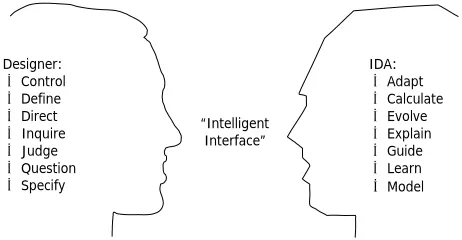
A characterisation of Mann and Coons’ design assistance philosophy is that of the Intelligent Design Assistant. Figure 1 illustrates some key complementary roles that a designer and an IDA are proposed to play within the scenario of intelligent CAD.
In this scenario, designers are initiators of a discourse, they retain authority and control over the progress of the interaction with the IDA, and have ultimate responsibility for the correctness of results. They are able to express the nature of the problem, to describe concepts to be explored, and to justify their judgements. In addition, they hypothesise, refer to past experience, and apply a range of modelling tools. In contrast, the IDA is the active partner to the designer. It is a source of design expertise and past experience that complements a designer’s memory. It is able to develop an understanding of a problem and description of concepts, assess the feasibility of concepts, identify the implications of concept changes, suggest possible solution paths, and can assume much of the burden of mundane and repetitive analysis tasks. The strengths indicated within Fitts’ list of the human are represented within the designer: perceiving patterns to express the nature of the problem; recalling relevant facts to describe concepts to be explored; and exercising judgement and reasoning inductively to justify their judgements. The strengths of the computer are represented within the IDA: reasoning deductively to identify the implications of concept changes; responding quickly to control tasks to suggest possible solution paths; and assuming the burden of repetitive and mundane analysis tasks.
Designer:
• Control
• Define
• Direct
• Inquire
• Judge
• Question
• Specify
IDA:
• Adapt
• Calculate
• Evolve
• Explain
• Guide
• Learn • Model “Intelligent
[image:3.595.183.414.502.622.2]Interface”
Figure 1. Intelligent Design Assistant (Copyright University of Strathclyde).
such as design within the made-to-order sector. The issue of complexity within the co-ordination of distributed design for example has been considered by Duffy, to consist of complexity of the following elements: the artefact being designed; the design activity itself; the actors involved; the design decision making process; the considerations impinging on design, and the knowledge and sources used and generated (Duffy, 1995). The VRS virtual platform aims to provide some level of support for all of these different types of complexity.
3
VRShips-ROPAX (VRS) & the VRS virtual platform
VRShips-ROPAX (VRS) was a pan European maritime project funded under the ‘competitive and sustainable growth’ theme of the 5th Framework in European Research. The strategic objective of VRS was to integrate information technology into the life cycle of a product, to sustain competitiveness through improving knowledge and technological skills, thus, following the previously successful pattern of other European industries (e.g. aerospace industry). The project focused upon integrating current effort dispersed throughout Europe to provide a standardised platform upon which a variety of maritime industries could function. Its aim was to support European Maritime Industries to:
• Maintain and improve their position against worldwide competition by improving
their knowledge and technological skills.
• Combine competitiveness/profitability with safety and environmental protection.
• Look at technology and innovation as the main way to survive in the global
international market.
The project was based on an industry partnership of 36 different groups within 34 different organisations from academic institutes, marine consultancies, marine research organisations, naval architects, ship builders and operators, port authorities and a standards organisation. Thus, the constituency supported and represented the requirements of the European maritime spectrum. The two main deliverables were a ‘generic virtual platform’ and a ‘ship platform of critical technologies’.
Whilst the focus here is towards the virtual platform, it is worth briefly mentioning the ship platform. A number of demanding and conflicting requirements were established for the design of the ship platform. Whilst the requirements were not as extensive as would be expected from a ship-owner, the requirements were chosen to push the boundaries of conventional ROPAX vessel design, with the resulting design representing an innovative leap. One aim within the VRShips-ROPAX project was to use conventional design tools to generate a design that satisfied the requirements, and subsequently repeat the process using the same tools within the context of the virtual platform to compare both the process of creating the design, and the design itself. The requirements for the design were: 2000 passengers, 400 cabins, 1.5 kilometres of vehicle lanes, 2000 nautical mile range, and 38 knot service speed. Individually, these requirements do not represent a difficult design problem; however the combination of passengers, cabins and vehicle lanes (which would normally result with a conventional hull shape), and the service speed (which would normally result with a slender hull shape – typically seen within warships) presented a situation where creativity was needed in order satisfy all requirements.
As well as providing a comparison between the conventional design approach and the
integrated design approach, the design would be used to produce a 1/
20 scale model of the
ROPAX vessel for testing, evaluation and comparison with the computational models used to simulate the performance, as well as to allow the testing of ship critical technologies, such as different propulsion systems for example.
3.1
VRS project structure
3.2
Platform overview
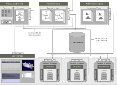
The approach adopted within the design of the virtual platform was to carry out an iterative process of development, test, implementation and evaluation leading towards the production of a complete virtual platform. The platform consisted of: tools and techniques to facilitate integration; a common model database for the storage of ship-product data; a “virtual” interface to the platform, the product and the process; an inference engine for the management of data dependency information; a process control tool for the co-ordination of process, activities and resources; and a “simulation engine” representing the design and simulation tools being integrated. The relationships between the components of the virtual platform can be seen within Figure 2.
User Interface Common Model Generic Wrapper Simulation Tool AVPro Local Model In put C o n v erter O u tput C o n v ert e r SSL Com Generic Wrapper Design Tool Tribon Local Model In put C o n v erter O u tput C o n v ert e r SSL Com Generic Wrapper Design Tool AVPro Local Model In put C o n v erter O u tput C o n v ert e r SSL Com
Process Control Tool
[image:5.595.100.493.197.482.2]Resources Requirements Processes SSL C o m SSL Com Inference Engine Dependency Maps SSL C o m Performance Analysis Performance Models SSL C o m Common Model Communication Virtual Platform Communication
Figure 2. VRS virtual platform components (Copyright University of Strathclyde).
extensive simulations, real time virtual interactions, performance analysis and life-phase support to be undertaken irrespective of the application domain or ship type.
3.3
Virtual platform objectives
The functionality and objectives of the main components within the VRS virtual platform were as follows:
Integration. The integration aim was to deliver a
strategy and architecture to guide the integration activities of the common model, virtual interaction, inference engine, process modelling and control, simulation engine and performance analysis and reliability components. The main objective of the integration framework is therefore to deliver a flexible protocol and communication mechanism that enables these disparate systems to integrate and co-ordinate their functionality. To achieve these objectives consideration therefore needs to be given to the platforms and programming languages that both the individual platform components and the integrated design and simulation tools use with the aim of developing a specification for the integration that was platform and programming language independent. Since the platform is distributed, consideration needs to be made to ensure efficient and effective communication of design information between the disparate entities.
Common model. The common model is a database
that provides a consistent representation of the data defining the ship systems (ship product model) and external environment (sea state, routes, port facilities), and holds the basic (and common) geometry and information required by each of the integrated simulation engine tools irrespective of the tools’ native data formats. The aim when defining the data specifications and schemas for the common model is to consider the functional requirements of the life-phase process models as well as the requirements of the integrated tools in order to ensure that the common model supports the design requirements of the user, as well as facilitating data transfer within simulation and real-time rendering programs developed within the virtual interaction component for example. Cover for the whole lifecycle of the vessel should be provided, from initial design to disposal; hence the data contained within it should be applicable across life-phases.
Virtual interaction. The common model allows
distributed manipulation of the ship product model as well as enabling the virtual environment by allowing the development of the product model using the tools within the simulation engine. The virtual environment
Integration component
Common model component
Virtual interaction component
ΞΜΛ
Ship Properties Geometry Structural Performance Propulsion
Sea State Routes Port Facilities Basic Productio Operation
STEP IGES DXF
XML-Based Neutral Format
is the interface that the users utilise in order to interact with the virtual platform. Since the project was EU funded, the partners and hence users of the platform were distributed across Europe. Providing access to the platform via the virtual interaction component however should be extendable such that it may be implemented either within an organisation, across stakeholder organisations, across partner organisations within Europe, or globally. The virtual environment should provide functionality to enable: multiple users; configuration and use of design and simulation tools; access to the common model; visualisation of common model contents; querying of data consistency status; enactment of processes, and use of the performance modelling tool.
Inference engine. The virtual environment enables
users to communicate and share product data and information through the ability to remotely access, query and modify the data contained within the common model. The design or simulation tools being integrated commonly have their own local model, represented either as local files or databases in their own native formats. Changing the data within one tool’s local model may have multiple implications or effects on other tools’ models. The main objective of the inference engine is to maintain the consistency between these various models through the management of change propagation and conflict resolution between multiple users irrespective of the native formats that the individual design and simulation tools use. The inference engine must manage: dynamic modification to common and local model data; the propagation of changes made to either common or local data throughout the data dependency network, the variation in information requirements, a mapping of the dependencies and relationships between data within the common model; and consistency management and conflict resolution.
Process modelling and control. The process control
tool is a planning and enactment environment for the co-ordination of activities within life-phase process models. This process control tool is used to define an initial sequence of activities, to determine an optimum process schedule, to manage the enactment of the tools within the virtual platform and to manage the processes under real-time conditions. Since the main objective of the process control tool is to demonstrate how distributed activities within a virtual platform can be managed and co-ordinated, there is also a requirement that the process control tool manages the resources that are capable of performing the activities, as well as co-ordinating when and why they should be undertaken.
Simulation engine. The simulation engine represents
the integrated design and simulation tools within the
Inference engine component
Process control component
Simulation engine component
Simulation engine component
? !!
? !!
AVPro
Early Design
Newdrift
Initial Design
Tribon
Production
…
XM
ST
XM
virtual platform. These tools enable the design of the hull, general arrangement, propulsion plant, subsystems, and simulation of the operating environment, operations, supply chain and production. The simulation engine is capable of allowing a through life assessment, ranging from concept development to performance trials and operational scenarios. The tools are “wrapped” in order to enable communication with the rest of the virtual platform.
4
Development of the VRS virtual platform
This section describes the components that combine to make the virtual platform. A prototype virtual platform was developed in order to determine the most appropriate technologies, to establish the mode of operation of the platform with respect to usability, and determine any shortcomings of the technologies used. Each subsection describes the results from the prototype development where applicable along with the lessons learned from the prototype in order to develop the next stage of the virtual platform.
4.1
Integration component
Rather than focus on the development of the communication mechanism and protocols, the prototype integration component focussed towards the use of an existing adapter to manage the operation of the design and simulation tools within the simulation engine. The design and simulation tools were distributed across a network with each tool individually managed by an adapter. The tools were mapped directly to activities within the process control tool, hence when a process was due to be undertaken, the process control tool would communicate with the appropriate adapter for the mapped activity to start the tool. The mapping of an activity to a tool limited the tool’s application to single activities whereas a number of the tools were capable of performing many design activities. The adapter was only capable of managing the start and completion of the tool, and provided no functionality to access the common model for example, and therefore restricted the overall integrated functionality of the platform. A bespoke wrapper was later developed specifically designed to address the integrated management of the design and simulation tools. From the perspective of Fitts’ list, the integration framework aimed to respond quickly to integration control tasks. These integration control tasks may for example be the process control tool allocating a conceptual design activity to a designer with the integration component providing a quick response between process control tool and designer. The prototype integration framework did however enable three key requirements to be identified with respect to the communication of data between the components:
• Message security. Secure Socket Layer (SSL) communication should be
implemented to utilise public/private key encryption, source authentication and data integrity for the transfer of data between virtual platform components.
• XML message format. XML should be used as the underlying language for
communication of data between virtual platform components due to its inherent extensibility and support throughout the IT community.
• Message validation. XML schemas should be used to automatically check that the
messages received by any of the virtual platform components conform to a defined standard.
Existing and well-established integration technologies such as the Common Object Request Brokerage Architecture (CORBA) were considered for the development of the integration framework. Within this context however, CORBA would have been implemented to facilitate the transfer of objects between the tools to be integrated, rather than enabling the insertion of the tools within the integrated platform.
available. In order to achieve this, consideration was given for the types of data to be communicated between the virtual platform components, the frequency of communication, and the type of communication (synchronous/asynchronous) when designing the protocol and communication mechanism. A functional protocol was defined based upon the Remote Procedure Call specification of XML (XML-RPC), unifying all of the protocols within the virtual platform into a single “generic” communication protocol – Figure 3. The protocol has elements to indicate the “sender” and “receiver” components in order that the receiver can check that it is a valid functional request from a valid sending component. The “functionName” element within the protocol is used to define the function (that is mapped to some functionality that the receiving component will perform) using the information contained within the “params” element.
An example of the use of the protocol would be a request from the generic wrapper to the inference engine to perform a status check on a piece of data before modification. A mapping would exist between the requested function and functionality encoded within the inference engine. Any number of parameters may be included within the protocol to enable the enactment of the function by the receiver. Both the sending and receiving components must agree in advance to the structure of the parameters, however the protocol is entirely neutral to the programming languages and the structure of the objects that are used by each component to represent the data.
<?xml version="1.0" encoding="UTF-8"?> <VRSMethod>
<sender>Sender</sender> <receiver>Receiver</receiver>
<functionName>FunctionName</functionName> <params>
<param>
<title>Title1</title> <value>
<string>String</string> </value>
</param> <param>
<title>Title2</title> <value>
<struct> <member>
<name>Name21</name> <value>
<int>42</int> </value> </member> <member>
<name>Name22</name> <value>
<double>3.14159</double> </value>
</member> </struct> </value> </param> </params> </VRSMethod>
Figure 3. XML-RPC functional protocol (Copyright University of Strathclyde).
Software was developed to enable the secure sending and receiving of XML-based communication between virtual platform components. An Application Programme Interface (API) was designed within the software to enable it to be integrated within each of the necessary components within Figure 2. Due to the dynamic nature of the communication within the virtual platform, it is difficult to predict when each component will be required to process communication, or whether the component will be sending and receiving multiple simultaneous communication. The communication software was therefore developed using a multi-threaded architecture to queue and sequentially process out-going communication, whilst allowing simultaneous prioritised processing of incoming communication.
4.2
Common model
inference engine (dependency maps), process control tool (process models) and the performance analysis and reliability tool (performance models). Three issues required consideration within the design of the common model: storage (how to store the data), structure (how to format the data), and coverage (what data to store). Since the common model, may in principle be used to store and manage large amounts of complex data, to be interactively viewed, added to and modified by a number of distributed users, the common model component addresses Fitts’ issue of handling many complex tasks simultaneously. These issues are however related since the selection of the storage mechanism depends upon the structure of the data to be stored (binary, XML, object-oriented). In addition, the structure of the data is influenced by the requirements of the tools to be integrated as well as the requirements of the users of the platform, and therefore influences and is influenced by the coverage. The current practices and standards used in formatting and structuring engineering data were investigated, including the Initial Graphical Exchange Specification (IGES) and the Standard for the Exchange of Product Model Data (STEP – ISO 10303), and the amount of data to be modelled (complete product information models for ships have been estimated by Catley to be of the order of between two and ten Gigabytes of data (Catley, 1999)). Considerable effort has been thrust towards the development of ISO 10303 STEP Application Protocols (APs) for Ship Arrangements (AP215) (2004a), Ship Moulded Forms (AP216) (2003), Ship Structures (AP218) (2004b), Ship Mechanical Systems (AP226 which has since been withdrawn), and Piping (AP227) (2001), – Grau (Grau, 1999). A number of occasions have arisen however when attempts have been made to adhere to these APs with the result that “flavours” of the standard have been required in order to utilise the structured, well-defined and standardised data within the legacy applications (Whitfield, 2003a). The focus when defining the coverage of the common model was therefore directed towards “the minimum amount of information that would enable the integrated tools to share an accurate representation of the product”. ISO 10303 Part 203 is used to define the 3D design of mechanical parts and was used within the common model as the basis upon which to define the geometry of any aspect of the ship product model. The selection of Part 203 also influenced the structure of the data to be contained within the common model.
Conversion of data to and from the common to native formats was also a significant issue that needed to be addressed, which would influence the structure of the data within the common model as well as how easily and successfully design and simulation tools could be integrated within the virtual platform. Having chosen to base the geometrical data within the common model on Part 203, the focus was then to complete the definition of the structure of the data, through the selection of an appropriate language that would facilitate conversion. EXPRESS (ISO 10303 Part 11 and 12) was developed as a language for the definition of STEP data. Major shortcomings of the EXPRESS reference language from a conversion viewpoint were that it was difficult to decompose EXPRESS-based models into more manageable chunks, and it was difficult for a human to interpret what the data within an EXPRESS file represented. Whilst human readability is not an issue during the process of converting data, it is certainly useful if the conversion algorithm developer can understand the concepts that are being converted whilst producing the algorithms. Attempts to undertake the conversion between formats have in the past faced difficulties due to the complexity and formatting of the data, and have in certain cases required a degree of human interaction (Rando, 2001). Research had been successfully conducted to produce a binding between STEP and XML (ISO 10303 Part 28) and has been applied within the shipbuilding industry (Rando, 2001) with the aim of facilitating the conversion process between the neutral STEP format and the native tool format. It was therefore concluded that an XML mapping of STEP data provided the most appropriate language upon which to base the storage of all data within the VRS platform due to its extensible nature, support for conversion, and the increasing support within the IT industry. Choosing to manage the data within the common model using XML, facilitated the selection of a storage mechanism.
database may be exchanged with alternative XML databases without impacting any of the software that communicates with the database. Documents are then managed within the database in hierarchical collections, similar to the directories within a file system.
4.3
Virtual interaction
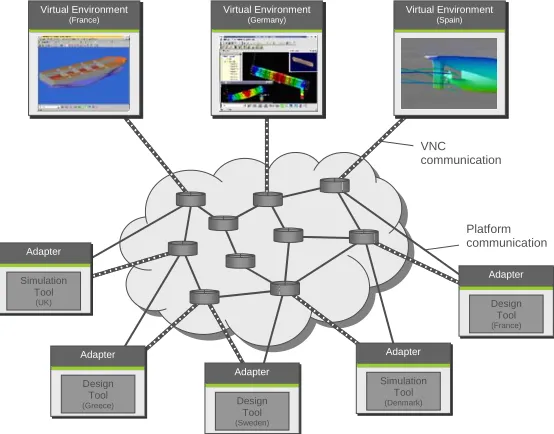
The virtual environment represents the “window” to the VRS virtual platform. It is intended to provide functionality to enable communication between, and use by multiple users, configuration and use of design and simulation tools, access to the common model, visualisation of common model contents, querying of data consistency status, enactment of processes and use of the performance modelling tool. The focus during the development of the prototype virtual environment was towards the production of an open architecture that would enable the configuration and remote use of design and simulation tools, and the visualisation of common model contents. A number of the design and simulation tools to be integrated into the platform had the ability to visually display the data in their local models whilst the user was operating the tool. Rather than developing and producing a new visualisation of the common model data within the virtual environment, the prototype environment initially attempted to enable the user interfaces of the remotely distributed tools to be exported to the virtual environment via the Internet using Virtual Network Computing (VNC) software. VNC enables the viewing and interaction of the desktop of a remote machine within a window of the local machine. The use of this approach meant that design and simulation tools could be “hosted” on remote machines, providing the facility for users to log onto the machine through the virtual environment and interact with the tool whenever required. New tools could be registered and integrated within the platform, and the functionality and visualisation aspects of the tools, utilised irrespective of where either the tool or user were geographically located, and without the need to generate any code to enable this integration - Figure 4. The display of one of these remote machines could in principal be exported to a number of other machines, facilitating the collaborative work of multiple users on the same design problem using the same design or simulation tools.
Integration
C i ti
P t l
R l ti hi
Adapter
Simulation Tool
(UK)
Adapter
Design Tool
(Greece)
Adapter
Design Tool
(Sweden)
Adapter
Simulation Tool
(Denmark)
Adapter
Design Tool
(France) Virtual Environment
(France)
Virtual Environment
(Germany)
Virtual Environment
(Spain)
Platform communication VNC
[image:11.595.159.436.424.641.2]communication
Figure 4. Remote export of visualization (Copyright University of Strathclyde).
situation, it was apparent that the network bandwidth could not support the refresh rates that were required for a smooth transition between frames.
Whilst there is currently VNC software available to support the secure communication of the encoded visualisation data, the security issues relating to the fact that the user has access to the entire desktop of the remote machine were considered to be unsatisfactory. The approach also raised issues relating to licensing of software – not only that used within the platform, but of all other tools available on the desktop of the remote machine, since tools would be available to all partners regardless of whether the user or partner has bought a license for it. The virtual environment was therefore developed to enable tools that each individual user has available to them locally, to be used within the virtual platform, and for these tools to be available to the users that have registered the tool and not throughout the platform. This change in operation and use of the design and simulation tools, had a significant impact on the rest of the platform: the virtual environment was developed to support the use of the tool to perform particular activities rather than as a means for distributed visualisation and collaboration, which impacted the process control tool with respect to the management of the users and the activities that they can perform, and not the tools that they use to perform them with.
The virtual interaction environment was developed to allow the user to log onto the platform, through interaction with the process control tool. Support was provided to integrate design and simulation tools into the virtual platform through the use of the generic wrapper configuration element. Textual communication between users of the platform was provided, as well as interaction with the inference engine and process control tool to determine the consistency status of data within the dependency maps and start processes for example. Distributed collaborative design was thus facilitated by the virtual interaction component and through the provision of interfaces to each of the individual components of the virtual platform provided an “intelligent interface” between the designer and the platform in a similar manner as that depicted within Figure 1.
4.4
Inference engine
The aim of the inference engine is to manage and maintain the consistency of the data within the common model through analysis of the relationships between the data. Data that resides within the local models of the design and simulation tools have inherent dependency relationships with the models of other tools and with the common model. Modifying the data within one local model may impact the models of other tools. The inference engine manages these relationships and ensures consistency between the tools by tracking the data usage of each of the tools and activities that are configured for integration into the virtual platform. Since the virtual platform enables multiple users to simultaneously conduct design and simulation activities, the inference engine also controls data access.
The inference engine has two modes of operation: an active mode through automatic interaction with the generic wrapper, and a passive mode through manual interaction via the virtual environment. The active mode is used whenever the user chooses to start an activity that has been scheduled and allocated to them via the process control tool. Functionality is provided within the active mode: for checking the status of the required data before the activity is started to determine if it is already locked for use by another user; locking the data if it is not already locked; automatically notifying other users of the change of the lock status of data that they may wish to use, and the management of potential conflicts that may arise as a result of multiple users modifying separate but related pieces of data.
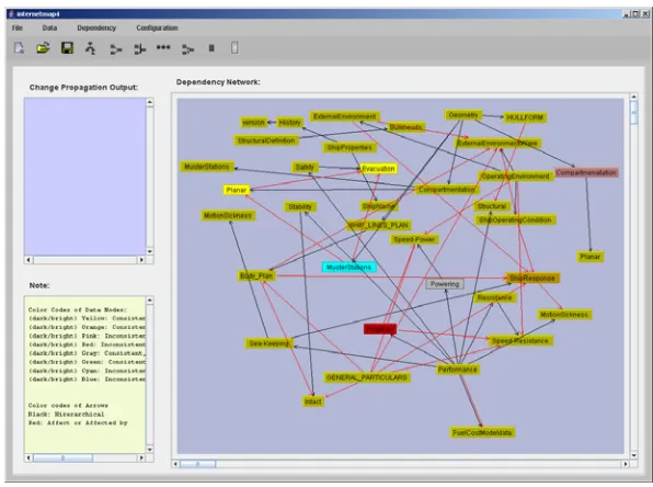
Figure 5. Inference Engine – Server side (Copyright University of Strathclyde).
The inference engine also provides passive functionality, acting as a server and interacting with the virtual environment to enable the users to query the locked or working status of data, facilitate co-operation between users operating on related pieces of data to avoid conflicts, attach notification triggers to data to inform the user when the state of the data changes, as well as modification of the data dependency network.
4.5
Process control tool
The prototype process control tool was developed to manage and enact processes through the communication with the adapters developed within the integration work package in order to start a design tool whenever a hull-form design activity requires enactment for example. Processes within the prototype process control tool consisted of activities that were directly mapped to tools that were capable of performing the activity. Due to tool management limitations of the adapter, it was not possible to provide any additional information to the tool regarding the rationale for undertaking the activity. In addition, each tool that was integrated within the virtual platform was mapped to an activity within a process of the process controller. From a process perspective; the tool could only be used to perform a single activity, whereas in reality a number of the tools were capable of performing a number of different activities. The prototype process control tool also had no formalised modelling of the capability of the resources that were logged onto a platform.
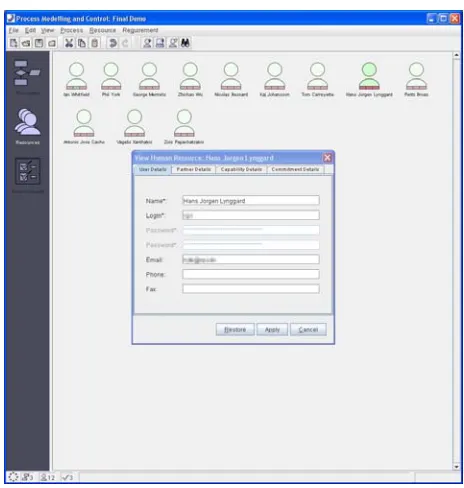
the resource’s IP address, as well as other contact details. Within the context of the virtual platform, the process control tool regards a resource as being an autonomous agent capable of performing an activity, and as such manages either human or computational resources. Whenever a tool is integrated, the user is expected to define the activity that they will perform with the tool. This mapping is provided as part of the configuration information of the tool within the virtual environment and not in the process control tool. Processes can therefore be managed and co-ordinated incorporating activities at any level of abstraction. Once the configuration is complete, the virtual environment communicates with the process control tool to update the resource’s details with information regarding this additional capability.
[image:14.595.181.413.166.410.2]Figure 6. Process Controller – resource model view (Copyright University of Strathclyde).
The process control tool can manage and enact simultaneous processes consisting of any number of interconnected activities – Figure 7. Since the process controller is capable of managing and enacting multiple processes simultaneously, in terms of activity allocation to resources, it addresses a number of strengths within Fitts’ list: responding quickly to control tasks, repetitive and routine tasks, and handling many complex tasks simultaneously. The activities (and the process control tool) were developed using object-oriented design procedures and are therefore not limited to the activity types defined below:
• Start Activity. The process control tool uses the start activity to determine the
starting point for the process as well as the activities that follow. Each process has exactly one start activity that is included within each process by default and cannot be removed.
• Design Activity. The design activity is used to define the nature of any activity that
would be allocated to a resource. Additional information is provided to the resource regarding a description of the activity, as well as an optional list of requirements that the resource will be expected to check to determine whether they have been satisfied once the design activity has been completed.
• Process Activities. The process control activities can be embedded within processes
to change the state (start, stop, pause, continue) of any of the other processes.
• AND Activity. Each of the activities defined above can only have one connection
• OR Activity. The OR activity is used in conjunction with a conditional activity, to
indicate that the process flow will continue when any of the preceding activities are completed.
• XOR Activity. The process control tool can manage conditions that return a logical
[image:15.595.189.408.335.563.2](true/false) result to indicate whether the condition has been satisfied such as the requirement for example which has it’s status set by a resource when it is associated with a design activity. The XOR activity checks the status of the condition that has been used to define it, and directs the process flow on the basis of the outcome. Conditional connections are used to connect the XOR conditional activity to other activities, to indicate the process flow that would be undertaken for each outcome. Two approaches are available to determine the most appropriate resource to perform an activity: single activity and multi-process scheduling. Single activity scheduling considers the request for a resource on an activity-by-activity basis. When a user configures a tool to be integrated within the virtual platform, the virtual environment communicates with the process control tool to register the user’s new capability. When an activity is due to be performed using single activity scheduling, the process control tool firstly generates a list of the resources that are capable of performing the activity. This list is then filtered to determine which of these user are currently online, as well as which are the most efficient at performing the activity. Single activity scheduling selects the most appropriate resource for each individual activity, without considering the process as a whole and hence cannot guarantee that the process lead times will be optimum.
Figure 7. Process controller – process view (Copyright University of Strathclyde).
scheduled resource some time the future. These issues could however be addressed by continually assessing the deviation from the schedule and re-scheduling when the deviation exceeds pre-defined limits (Whitfield et al., 2003b).
4.6
Simulation engine
The simulation engine represents all of the design and simulation tools that are integrated into the virtual platform. These tools represent the functionality that is required to design the ROPAX vessel from concept to detail, and simulate the performance of the ROPAX vessel with respect to the environment, operations, supply chain and production. In order to enable this design, the associated design and simulation tools require integration within the virtual platform. Additional management functionality was however required within this wrapping in order that the tool usage could be co-ordinated. This functionality was provided in the form of a generic wrapper, consisting of two separate modules, which would be used to integrate any of the simulation engine tools within the platform.
The focus when developing the generic wrapper was on facilitating the open architecture and providing support for any tool irrespective of the function that the tool provides, the programming language that it was written in, or the platform that it operates on. The configuration module is a graphical interface that enables the generation of tool integration information, relating to the management of input and output data, data conversion algorithms, and design and simulation tools.
Once the configuration of the tool is complete, the associated activity becomes available for enactment within the interface of the user’s virtual environment. Information is also sent to the process control tool to inform it that the user is now capable of performing the configured activity.
When an activity within a process has been scheduled to a resource, the process control tool communicates with the virtual environment of the resource informing it that the activity needs to be performed. The enactment module downloads the data from the common model, converts the input data to the native format, runs the design and/or simulation tools, converts the output data to the neutral format once the tool use is complete, and uploads the data to the common model in accordance with the rules defined within the configuration. The enactment module also manages communication with the inference engine to check the lock status of any of the data that it will be using. A dialog is displayed if the required data is already in use (and therefore locked). Alternatively, the inference engine will lock the data for the user during the enactment of the activity.
5
Use of the VRS virtual platform
When the user starts the virtual environment component, they are presented with a login dialog to control access to the virtual platform. The user is expected to provide information relating to their username and password. The process control tool prohibits further access to the platform if the details do not match those contained within an encrypted database. Once the username and password have been validated, the process control tool registers the details to indicate that the user is online in order that activities may be scheduled and allocated to the user in the future.
The first time the user logs onto the platform, the virtual environment will create a new profile, hence the user is expected to use the configuration module of the generic wrapper in order to define the activities that the user can perform – see Section 4.6. Once the user has completed the configuration procedure, the associated activities that have been mapped are registered with the process control tool as new capability.
available tools. This representation does not however allow modification of the data in the same way that the design and simulation tools would. The virtual environment also allows manipulation of the data dependency maps within the inference engine, and starting of processes within the process control tool.
When a process is started, the process control tool will firstly attempt to allocate resources to the activities within the process that require resources using either single activity or multi-process scheduling – see Section 4.5. Once a resource has been identified, the multi-process control tool will communicate with the virtual environment of the resource and allocate the activity to them. When the activity is started, the configuration information is loaded into the generic wrapper enactment module, which will extract the information relating to the input and output data that the associated tool will use. The enactment module will then communicate with the inference engine in order to establish the status of the data. If a different user has already locked the data, the inference engine will inform the user that they may only use a copy of the data, or alternatively defer the activity until later. If a copy of the data is used, any data that is generated from the copy cannot be uploaded to the common model. This limitation is made to prevent inconsistencies arising from multiple users simultaneously accessing and modifying the same piece of data. If the data is locked, the user may interact with the inference engine via the virtual environment to either: request notification when the lock is released; establish which resource has locked the data and communicate with the resource in order to collaboratively work on the data. If the data is not locked when the user starts the activity, the inference engine will automatically lock the data, and allow the user to modify it in accordance with the configuration. The inference engine will also check to see if any other user has currently locked (and is therefore working on) any related data through analysis of its data dependency maps. For example, user A may currently be using the hull-form of the ship to conduct a damage stability analysis, whilst user Z is allocated an activity to modify the hull-form. A relationship would exist within the inference engine between the hull-form and the damage stability performance through the configuration of the damage stability analysis tool by user Z. If user A makes a modification to the hull-form, it could impact the simulation activities of user Z. The inference engine would therefore communicate with both users and provide notification that the activities that they are performing could potentially be in conflict with each other. Given this notification of a potential conflict, it is left up to the associated users to ensure that the actions that they undertake do not result with an actual conflict.
Once it has been established that the data either isn’t locked, or is locked and therefore copied, the generic wrapper enactment module will download the data from the common model, store it in the defined locations on the user’s local machine, run the conversion algorithms, and the pass the converted input data to the tool which is then started. The design or simulation tool may then be used in a manner according to the requirements of the activity. Given the nature of the VRS design problem, many of the design tools require a significant amount (days, weeks or months) of effort in order to generate the required output. Hence provision is provided within both the virtual environment and the generic wrapper to enable the activity to be stopped, and re-started any number of times, without repeating the process of checking for data locks, and downloading the data. The data that is associated with the activity remains locked until the activity is completed.
requirement is not satisfied, the process control tool may either: re-direct the process to activities that are known to affect the requirement, or ignore the failed requirement and direct the process as planned with the knowledge that the requirement will be satisfied later.
The process control tool also has functionality to enable users of the virtual platform to attach notes to the details of an activity once the activity is completed. This functionality enables a user to provide precise details of the activity that they have performed. For example, it may be necessary to modify the general arrangement if it is established that the evacuation time for the vessel is not appropriate, and in doing so, the user responsible for modifying the general arrangement has repositioned a bulkhead. The user can therefore attach a note to state that the bulkhead has been repositioned, in order that any subsequent activities can consider the new bulkhead position. Alternatively, the user may attach a note to state the reason why a certain requirement was not satisfied. These notes are propagated throughout the processes by the process control tool and may be added to or removed when appropriate by the allocated resources and provides a means of directing design activity towards specific issues.
A number of evaluation scenarios were created in order to test the virtual platform during the development of both the prototype and the current version. The most recent scenario had users distributed across Europe in France, Greece, Sweden, and the UK, logged onto the platform and co-ordinating their activities to demonstrate the design of a vessel, from a hull-form concept, through to the detail design of the hull including hull-fairing, generation of the general arrangement of the decks within the hull using the hull-form profiles at various sections, and finally generating a simulation of the performance of the vessel with respect to the evacuation of 2000 passengers. The focus of these demonstration scenarios was not on the actual design, but on the operation and performance of the virtual platform in supporting the design.
[image:18.595.162.435.493.711.2]The designers were free to operate with the tools, techniques and expertise that they would conventionally use. No constraint was placed on the designers in terms of how they would undertake their normal duties through the virtual platform. Decision support was provided to the designers in terms of getting the right information to the right designer at the right time. The designers are otherwise not supported in their decision-making, with the assumption that they are already in possession of the expertise to be able to make the right decisions. The provision of the right information however enables the designers to make informed decisions. The output of the conventional design approach satisfying the design requirements can be seen within Figure 8.
From a creativity viewpoint, the essential difference between the conventional approach and the integrated approach arises as a result of the availability of new types of information. Since the integrated approach allowed the inclusion of previously disparate (simulation) tools that may not have been included within the design process, the output from these tools may be used to influence the design. In certain circumstances this additional information can constrain the solution space by providing a more comprehensive understanding of the viability of the design. In doing so however it directs the designer towards the solution in a more informed manner. Following the geometric definition of the hull envelope, the General Arrangement (GA) may itself be constructed from “modules” from previous vessels. Given the GA, the integrated platform allows the addition of compartmentation representing meta-information of the topological layout of cabins, corridors and stairs for example. The output from this compartmentation would then be automatically transferred to a tool that simulates evacuation of passengers, the result of which would be a quantitative estimate of how long it would take passengers to evacuate to the muster stations, as well as a qualitative view of where the evacuation bottlenecks are (typically stairwells) - Figure 9. Whilst these simulations are being undertaken, the conventional design activity using the GA would also be operating in parallel. The output of the evacuation could however be used to modify the GA, when additional design work is usually necessary within further iterative cycles to modify the GA. The platform therefore manages the complexity of the design process integrating simulation wherever it is appropriate, as well as the complexity of the data to enable it to be efficiently transferred between tools, such that the output may be presented to the designer at the right point to inform their decision-making.
Figure 9. Evacuation simulation software (Copyright Safety at Sea Ltd.)
6
Future developments and challenges
The concept of providing distributed design support has been successfully demonstrated within the VRShips project, and will be further developed within a number of EU-funded projects. These developments aim to enable a more dynamic aspect to this support – creating processes on the fly and providing support on an ad-hoc basis where required. In addition, support will be provided to processes, tasks and activities irrespective of the life-phase that they represent, with minimal cognitive impact on the user.
the activities that they were dependent upon were complete. Multiple activities could be undertaken in parallel, however no support for overlapping dependent activities was provided. The consequences of providing this support are however significant and could form the basis for future developments. Assuming that two dependent activities are completely overlapped, and are therefore running in parallel, the two resources performing the activities will be required to be made continuously aware of the actions and outcomes of each other. Changes made to the design for example therefore require continuous broadcast to all the resources that are affected by the change. Similarities may be drawn and techniques adopted within the computer gaming industry whereby servers run environments that contain many users interacting with the environment and with each other. The changes that are made to the environment are continuous and don’t rely on a user completing their activities before being broadcast to other users.
Where the VRShips platform was generalized in every aspect other than the data contained within the common model, providing continuous activity support rather than discrete would require a large amount of domain specific knowledge to be supplied to the user. The tools that the user normally operates would require wrapping of source code to enable the dynamic transfer of data during operation to other users. A task or activity level co-ordination layer would still be necessary to avoid chaotic behaviour, but would provide support for dynamically created processes and would respond to as well as guide the users actions in both a planned and ad-hoc manner. This activity level co-ordination layer would therefore require domain specific knowledge to be gathered regarding the users actions, to be used as a basis for establishing a new course of action.
The virtual platform developed within the VRShips-ROPAX project is currently being exploited within other European Union funded projects within the shipbuilding industry. These projects are aiming to further develop the concepts within different contexts where the long-term strategic focus is towards the production of a commercially viable platform. The success of the platform has been demonstrated within a number of ship design scenarios where the design activity has been predominantly undertaken by designers within the shipbuilding industry. Since the components that manage the complexity of the design process are generic (the integration platform, common model, inference engine, process control tool and the generic wrapper), the platform is equally applicable to other sectors where complexity within the design process is an issue, such as the large made-to-order industry. Implementing the platform within a different domain would require the definition of a neutral data structure to represent the data being generated and transferred between tools, as well as the production of input/output data converters between the tools. This is perceived to be the minimum development for integration of domain specific design and simulation tools if a standard data representation does not exist. If a standard exists, the platform may be used within the domain without any modification.
7
Acknowledgements
The authors would like to acknowledge the funding received to enable this research to be undertaken. The VRShips-ROPAX project was funded by the European Commission (grant number G3RD-CT-2001-00506), which is part of the Fifth Framework Programme for Research, Technological Development and Demonstration.
8
References
(2001) Industrial automation systems and integration - Product data representation and exchange - Part 227: Application protocol: Plant spatial configuration. International Organization for Standardization.
(2003) Industrial automation systems and integration - Product data representation and exchange - Part 216: Application protocol: Ship moulded forms. International Organization for Standardization.
(2004a) Industrial automation systems and integration - Product data representation and exchange - Part 215: Application protocol: Ship arrangement. International Organization for Standardization.
CATLEY, D. (1999) Prototype STEP data exchanges in ship initial design and the provision of an applications programmer interface to "Tribon". IN CHRYSSOSTOMIDIS, C., JOHANSSON, K. (Ed.) International Conference on Computer Applications in Shipbuilding. Massachusetts, USA, Massachusetts Institute of
Technology.
CHAPANIS, A., FRICK, F. C., GARNER, W. R., GEBHARD, J. W., GRETHER, W. F., HENNEMAN, R. H., KAPPAIF, W. E., NEWMAN, E. B. & WILLIAMS, A. C. (1951) Human engineering for an effective air navigation and traffic control system. IN P.M.FITTS (Ed.) Washington D.C., National Research Council.
CUMMINGS, M. L. (2004) Automation bias in intelligent time critical decision support systems. AIAA 1st Intelligent Systems Technical Conference. Chicago, American Institute of Aeronautics and Astronautics.
DUFFY, S. M. (1995) The design complexity map and the design co-ordination framework. 10th Integrated Production Systems Seminar. Fuglso, Denmark, Insistute of Engineering Design.
GRAU, M., KOCH, T. (1999) Applying STEP Technology to Shipbuilding. IN CHRYSSOSTOMIDIS, C., JOHANSSON, K. (Ed.) International Conference on Computer Applications in Shipbuilding.
Massachusetts, USA, Massachusetts Institute of Technology.
GUAN, X., DUFFY, A. H. B. & MACCALLUM, K. J. (1997) Prototype system for supporting the incremental modelling of vague geometic configurations. AIEDAM special issue of Geometric Representation and Reasoning in Design, 11, 287-310.
MANFAAT, D., A.H.B. DUFFY (1998) SPIDA: abstracting and generalising layout design cases. Artificial Intelligence for Engineering Design, Analysis, and Manufacturing, 12, 141-159.
MANN, R. W. & COONS, S. A. (1965) Computer-aided design. McGraw-Hill Yearbook Science and Technology.
New York, McGraw-Hill.
RANDO, T. C. (2001) XML-based interoperability in the Integrated Shipbuilding Environment (ISE). Journal of Ship Production, 17, 69-75.
WHITFIELD, R. I., A.H.B. DUFFY, J. MEEHAN, Z. WU (2003a) Ship product modelling. Journal of Ship Production, 19, 230-245.
WHITFIELD, R. I., DUFFY, A. H. B., COATES, G. & HILLS, W. (2003b) Efficient process optimisation.
International Journal of Concurrent Engineering: Research and Applications, 11, 83-92.
YAN, X. T., REHMAN, F. & BORG, J. (2002) Foreseeing design solution consequences using design context information. IFIP Working Group 5.2. Malta.
ZHANG, Y., MACCALLUM, K. J. & DUFFY, A. H. B. (1997) Product knowledge modelling and management.