White Rose Research Online URL for this paper:
http://eprints.whiterose.ac.uk/130838/
Version: Published Version
Article:
Almansoori, A.M.M., Masters, R., Abrams, K. et al. (4 more authors) (2018) Surface
modification of the laser sintering standard powder polyamide 12 by plasma treatments.
Plasma Processes and Polymers, 15 (7). 1800032. ISSN 1612-8850
https://doi.org/10.1002/ppap.201800032
[email protected] https://eprints.whiterose.ac.uk/
Reuse
This article is distributed under the terms of the Creative Commons Attribution (CC BY) licence. This licence allows you to distribute, remix, tweak, and build upon the work, even commercially, as long as you credit the authors for the original work. More information and the full terms of the licence here:
https://creativecommons.org/licenses/
Takedown
If you consider content in White Rose Research Online to be in breach of UK law, please notify us by
F U L L P A P E R
Surface modification of the laser sintering standard powder
polyamide 12 by plasma treatments
Alaa Almansoori
1,2|
Robert Masters
1|
Kerry Abrams
1|
Jan Schäfer
3|
Torsten Gerling
3|
Candice Majewski
4|
Cornelia Rodenburg
11Department of Materials Science and
Engineering, University of Sheffield, Sir Robert Hadfield Building, Mappin St, Sheffield S1 3JD, United Kingdom
2Southern Technical University, Basra, Iraq 3Leibniz Institute for Plasma Science and
Technology, Felix-Hausdorff-Straße 2 Greifswald 17489, Germany
4Department of Mechanical Engineering,
University of Sheffield, The AdAM Centre, Garden Street Sheffield S1 3JD,
United Kingdom
Correspondence
Alaa Almansoori, Department of Materials Science and Engineering, University of Sheffield, Sir Robert Hadfield Building, Mappin St, Sheffield S1 3JD,
United Kingdom.
Email: [email protected], [email protected]
Funding information
Ministry of Higher Education and Scientific Research; Engineering and Physical Sciences Research Council, Grant number: EP/N008065/1; Royal Society,
Grant number: IE160969; German Ministry of Education and Research (BMBF), Grant number: 13N11188
Polyamide 12 (PA12) powder was exposed for up to 3 h to low pressure air plasma treatment (LP-PT) and several minutes by two different atmospheric pressure plasma jets (APPJ) i.e., kINPen (K-APPJ) and Hairline (H-APPJ). The chemical and physical changes resulting from LP-PT were observed by a combination of Scanning Electron Microscopy (SEM), Hot Stage Microscopy (HSM) and Fourier transform infrared spectroscopy (FTIR), which demonstrated significant changes between the plasma treated and untreated PA12 powders. PA12 exposed to LP-PT showed an increase in wettability, was relatively porous, and possessed a higher density, which resulted from the surface functionalization and materials removal during the plasma exposure. However, it showed poor melt behavior under heating conditions typical for Laser Sintering. In contrast,
brief PJ treatments demon-strated similar changes in po-rosity, but crucially, retained the favorable melt characteristics of PA12 powder.
K E Y W O R D S
atmospheric pressure plasma treatment, laser sintering, scanning electron microscopy, surface modification, wettability
1
|
INTRODUCTION
During the last decade, laser sintering (LS) has become one of the most promising polymer Additive Manufacturing techni-ques, capable of manufacturing 3-dimensional (3D) products with complex and accurate geometries from powdered materials. However, the range and reliability of materials
for this process is currently a limiting factor; the ultimate aim of this research is to address this issue.[1–5]
Polyamide 12 (PA12) powder is frequently selected for LS applications due to its easy (i.e., ease of sintering), large processing windows, high laser energy absorption, and good mechanical properties.[5–7]
Despite this potential, however, the consistency of mechanical performance of LS parts made
This is an open access article under the terms of the Creative Commons Attribution License, which permits use, distribution and reproduction in any medium, provided the original work is properly cited.
© 2018 The Authors.Plasma Processes and PolymersPublished by WILEY-VCH Verlag GmbH & Co. KGaA, Weinheim
Plasma Process Polym.2018;15:e1800032. www.plasma-polymers.com
|
1 of 12from PA12 powder needs to be improved by the inclusion of fillers. Nano-materials such as nanoclays have potential in this area, but their dispersion can be difficult. Plasma etching has been used to improve dispersion and therefore make these nano-materials more viable.[8,9]
LS-PA12 parts with many other polymers have also restricted applications where adhesive bonding of polymers with other materials, wettability, or printability are required, due to their poor hydrophilic properties.[10] PA12 powder tends to have the lowest swelling and solubility in polar solvents like water due to its longer methylene chain and strong hydrogen bonds between the amide groups of the PA12.[11] Consequently, different surface modification techniques, for instance, wet chemical and/or plasma treatment have been frequently used to modify the polymeric surfaces for such applications.[12]
Plasma-based surface modification has been used extensively in the past decade due to its favorable properties, such as lack of toxic chemicals or waste products; therefore, it is considered as an environmentally friendly method.[12] Plasma surface modification is used mainly to tailor the surface chemistry by enhancing the polymeric surface energy. Plasma- a reactive medium containing free electrons, excited and ionized atoms and molecules, radicals, and metastables and VIS-UV radiation is widely applied also for chemically modification of polymer surfaces,[10,13–15] e.g., ultrafine cleaning,[16,17] functionalization,[18] etching,[19] or thin film deposition.[20]Atmospheric pressure plasma jets are used to improve the wettability and adhesion,[10,21–23]as is low pressure plasma.[13,24,25] Both of these techniques are investigated in this work, although the plasma jet, can be expected to have an advantage that it is more economical than the low pressure ones requiring a vacuum chamber.[10,26]An optimal use of plasma treatment promotes the surface functionality and dampens structural degradation of original material. For this purpose, an advanced characterization of chemical properties is required in correlation to plasma process settings (gas, pressure, excitation frequency, power). Different gases or gas mixtures for example, Argon or Fluorine based plasmas such as CF4and oxygen gas plasma, are used for the
surface hydrophilisation or hydrophobisation of polymers.[23–
25]
Plasma based technique is a common way but not the only method, other types of methods like grafting or electron beam irradiation can also be used to manipulate the surface properties of materials.[27–29]
Several attempts have been carried out to modify a wide range of polymers using plasma for different purposes.[13,30–32] Studies focused on the plasma treatment of PA12 are concentrated on the bulk material, thin films,[10,22,33–35] or fibers.[36] A significant plasma effect on solid materials is limited to the topmost surface layer, the thickness of which depends on the plasma power and exposure time.[37]Within this surface layer, the chemical structure and properties
(e.g., mechanical properties) differ significantly from those of pristine materials or from the bulk.[10,32,33] Hence, a phase separation in the region between the surface and bulk materials can occur.[38]Aging and degradation of the plasma-assisted active sites after exposure to the ambient environment is another common issue which is caused by the interaction between the surfaces free radicals and environmental oxygen.[32,39]
Further, the practical application of plasma treatments to complex-shaped laser sintered parts is challenging. As a solution to these issues, we suggest using plasma treatment on polymer powders (PA12 is the target material) before sintering. Laser Sintering of plasma treated powder is in its infancy, and studies in this field are very rare. In a recent work, LS-PA12 powder was plasma treated to observe whether the plasma treatment changes the powder surface tension.[40] This study was aimed to present a correlation between the measured and estimated surface tension of the powder and melt for understanding the LS processes and additional qualifying new materials.
Here, we conduct a comprehensive study of the usability of plasma treated PA12 powder in laser sintering for applications which require high hydrophilicity. Surface chemical reactions and microstructure development were considered in this paper toward a better understanding of the plasma treatment mechanisms and benefits. Downward heat sintering (DHS) was used as a casting method to mirror the technology of laser sintering but on smaller powder quantities to reduce cost and waste products for Additive Manufactur-ing. DHS was used only to cast the nontreated and LP-PT treated PA12 powder as the PJ treated powder has shown its meltability during plasma exposure. This study is a part of a series of works linking plasma treatment and its advantages on polymers or polymer composites for laser sintering applications.[8,9]
2
|
MATERIALS AND
EXPERIMENTAL
2.1
|
Materials
Polyamide 12 (PA12) (often named as Nylon12) supplied by e-Manufacturing Solution (EOS) is a white, odorless, thermoplastic and semicrystalline polymer. PA12 is selected for this study as, by far, it is the most established and commonly used laser sintering powder. PA12 is an aliphatic polymer with structure as displayed in Figure S1. The powder batch used in this paper comprised 50% recovered powder from previous Laser Sintering builds, blended with 50% virgin powder, as is standard in industry.
PA12 particles, as shown in Figure S1a, often have rounded or potato shape with an average size of 60–80μm
In Figure S1b, higher magnification SEM image of a single PA12 particle before treatment, shows a non-porous solid surface. In SEM image in Figure S1b, we observe that the PA12 particles were covered by white nanosized particles which are assumed to be TiO2which are added to improve the
powder whiteness.[41]These nanoparticles look whiter due to their higher refractive index, which means the TiO2 has a
higher scattering light affinity than the PA12 particles.[42,43]
2.2
|
Plasma treatment technologies
2.2.1
|
Low pressure air plasma treatment
(LP-PT)
As polymers are heat-sensitive materials, a cold plasma treatment was required to provide low temperature surface modification. A Zepto plasma cleaner from Diener Electron-ics was used in this study.
PA12 powder (≈3 g) was placed in thin layers in a glass
petri dishes in the plasma cleaner chamber (glass cylindrical chamber), exposing only the surface of the powder layer to the plasma. Thus, the powder was turned half way through the stated treatment time as shown in Figure S2 to increase the homogeneity of the treatment.
After placing powder in the plasma chamber, that was evacuated before running the plasma. Air gas plasma (ambient air is the process gas) generated inside a glass cylindrical chamber was applied by a strong electric field in between two electrodes. Oxygen molecules are activated and dissociated into reactive species, atoms, radicals, ions, and electrons. The plasma generator is switched on when working pressure has been achieved (3 mbar or less). However, this pressure changes slightly after generating the plasma. Then, plasma system receives continuously fresh gas while the contaminated gas is evacuated. PA12 powders were treated at 100 W power for 1, 2, and 3 h respectively, the treated powder was then removed and stored in a sealed glass jars.
2.2.2
|
Atmospheric pressure plasma jets
(APPJ)
The direct treatment of PA12 powder was conducted using two different cold atmospheric pressure plasma jets i.e., kINPen (K-APPJ) and Hairline (H-APPJ) the differences between the two pen sources are shown in the table in Figure S3 but essentially the K-APPJ has a higher power than H-APPJ. The operating gas mixture here is Argon. PA12 powder was treated at atmospheric pressure for 1, 3, and 6 min. A thin layer of PA12 powder was placed on a small metal stub with a distance≈1 cm between the plasma
pen and the powder.
2.3
|
Sample fabrication methods
LP-PT and non-treated PA12 samples were produced via Downward Heat Sintering method (DHS) to mirror the laser sintering as described in.[9]PA12 powders were placed in a hollow mould in between the upper and lower parts of the hot press for 30 min in two stages. First, the powder was preheated in the lower part at a temperature 185 °C for 15 min before the upper part at a temperature 190 °C was brought down for another 15 min. Thus, samples and parts were cast without applied external pressure with a downward supplied heat energy, therefore the DHS was considered as a good indicator for the laser sintering. In the laser sintering process, parts were produced by laser energy layer-by-layer supplied on a preheated powder bed. The main parameters of laser sintering process are: part bed preheating temperature- 170–172 °C; laser power-13–21 W; laser speed scan 2500 mm sec−1; layer
thickness- 0.1 mm; and scan spacing- 0.25 mm.
2.4
|
Characterization and Testing
2.4.1
|
Morphology investigations by scanning
electron microscopy (SEM)
Low Voltage Scanning Electron Microscopy (NovaSEM) was used to analyze the morphology. An electron beam with a low landing energy (2.2 KeV) was used to reduce the specimen surface charging and damage. Note no metal coating was applied to the polymer surface. In addition, two different detectors were used to image the powder and bulk samples; a Through-lens-detector (TLD) for secondary electron (SE) imaging at low magnification and concentric back scatter detector (CBS) using back-scattered electrons (BSE) to obtain high magnification images. A Low Voltage FEI Sirion (FEGSEM) was used for imaging the 1 and 3 min K-APPJ treated PA12 at low voltage up to 1 kV primary beam and 4.8–4.9 mm working distance, with SE collected using the immersion-lens TLD. A Low Voltage FEI Helios SEM specifically designed for high resolution imaging at low voltages <1 kV and working distance of 4 mm was used to probe the nontreated and H-APPJ treated PA12 powders. All micrographs were processed to enhance contrast.
2.4.2
|
Wettability and density measurements
The densities of PA12 (nontreated, 1 and 2 h treated) were measured using Gas Pycnometer (Accupyc II 1340) from micromeritics.
2.4.3
|
Fourier transform infrared
spectroscopy (FTIR) and hot stage microscopy
(HSM)
FTIR analysis was performed using a PerkinElmer Frontier spectrophotometer equipped by Golden GateTM-single re-flection Diamond ATR accessory. FTIR measurements were carried on LP-PT treated and nontreated PA12 powders (without KBr dilution) by recording 10 scans of the wavenumber range from 500 to 4000 cm−1with a spectral resolution of 4 cm−1. Before obtaining spectra from the samples, a background spectrum with no sample was taken as a control. HSM was performed on BX50 light microscope from Olympus attached to a temperature-controlled microscope stage from Linkam.
3
|
RESULTS AND DISCUSSION
3.1
|
Visual observation and chemical
reactions description
The reactive plasma species attack the polymer surface leading to physical and chemical changes on the exposed
polymer surface, e.g., changes of crystalline forms, macro-radical generation and splitting of the macromolecules into fragments. One of the most frequently occurring reactions is polymer oxidation, particularly when oxygen-containing plasma is used in the treatment process. As can be clearly seen in Figure 1a, a dramatic change in the color of the PA12 powder was observed as the pristine PA12 powder is white and becomes light brown after a 1 h exposure, and a darker brown after 2 h. The treated and nontreated powders were also pressed into solid discs with the disc surface displaying a uniform color which reveals that only fewer powder particles were not well-exposed (see Figure 1b). Activated atoms and molecules in the electric field during plasma exposure react with the modified surface, creating new oxygenated groups and new chemical functionalities.[13–36]
Polymer oxidation can therefore occur when the oxygen atoms attack the activated surface leading to hydrogen abstraction (separation) from the polymeric chain, and forming free radicals, which can react to the oxygen in the plasma field. PA12 has a weak resistance to UV radiation and exposure weakens the C─C and C─H bonds. As described
earlier, the PA12 particles were covered by TiO2
[image:5.594.134.465.419.689.2]nano-particles (see inset image in Figure S1b), and the inclusion of photoactive particles could play a critical role in enhancing the production of radical species.[43]In an environment rich with oxygen and radicals (see Figure 1c), this enables chemical reactions that produce volatile products like CO and
CO2, new functional groups, i.e.,−OH and−COOH[13]and
physical changes like the discoloration.[44]Volatile molecules created were subsequently boiled off and swept away by the vacuum pump leading to the formation of pores and holes. Besides the formation of new chemical functionalities, powder surface etching and powder discoloration, surface activation by oxygen plasma often leads to increased surface energy and roughness, morphological changes, and enhanced wettability. Surface energy is increased by the formation of immobilized free radicals through the generation of dangling bonds.[37]Immobilized free radicals are reactive and unstable, however have higher kinetic stability and longer lifetimes than mobile, free radicals.[37] It is also worthy to note, although oxygen is the most active gas in the air plasma treatment, nitrogen N2gas (ions or atoms) also interacts with
the polymeric surfaces and chemical abstraction leading to the formation of volatile products like NO and NO2.[26]
3.2
|
Surface morphology investigations by
SEM
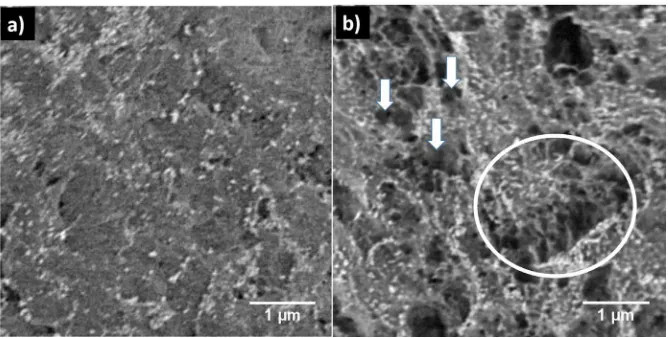
The morphological surface changes of the plasma-exposed particles can be observed in the SEM micrographs in Figure 2.
Distinct differences between nontreated (Figure 2a) and treated PA12 (Figure 2b) particles are observed in the BSE-SEM images. Both exhibit dark areas, which are pores or cracks[45]and very bright nanostructures which we assume are the TiO2 nanoparticles present in the nontreated PA12
powder.[41]The nontreated powder exhibits few nanopores, while the LP-PT powder contains micron size pores. Less obvious is the change in distribution of the bright nano-structures with visible accumulations of the latter at the pores edges (examples are marked with arrows and circle in Figure 2b). This contrast reveals a heterogeneity in the molecular weight and topography of the treated particle surface due to the plasma species coupled with the UV radiations.
The heterogeneous surface morphology is attributed, as mentioned above, to the dissociation of carbon bonds and conversion to CO and CO2gases and other volatile chemical
compounds, resulting in surface etching, and material loss.[25,26]The formation of pores in this section (shown in Figure 2b) especially those with a size of a few hundredμm,
[image:6.594.133.467.49.218.2]was possibly due to the chemical changes induced by the plasma species and UV radiation. The chemistry of the etch products is discussed in the FTIR analysis sections.
[image:6.594.71.521.605.701.2]FIGURE 2 SEM micrographs of the PA12 particles surfaces (a) without LP-PT plasma treatment, (b) 1 h LP-PT plasma treated PA12 (porosity examples marked with circle and arrows)
3.3
|
Powder wettability and density results
The polymer-water interaction significantly changed after plasma exposure as shown in Figure S4 and S5 and Figure 3. As can be observed in Figure S4, the LP-PT treated PA12 powder was easily spread over the water surface just before penetrating the water surface, suggesting that the plasma treated powder was rendered wettable (hydrophilic). On the other hand, the nontreated PA12 powder aggregated on top and revealed poor wettability as shown in Figure S4. For a deeper insight, photographs were taken of the LP-PT treated and nontreated PA12 powders, at 1 min and 1 h intervals after mixing and stirring with water (Figure 3a-c and Figure S5). As can be observed in Figure 3a, the LP-PT plasma-treated PA12 powders tended to spread and disperse within water before stirring while the nontreated PA12 powder remained on the top. During stirring, the treated powder became well-dispersed in the water changing the color of the treated powder-water mixture to that of the treated powder, whilst the nontreated powder was suspended in the stirred water leading to a“milky”appearance of the powder-water suspension as seen in Figure 3b. After stirring, some of the treated powder particles began to settle at the bottom, whilst others floated either at the top or within the jar space (see Figure S5 in supporting information). In a photograph taken after 72 h, all the powder either settles at the bottom (wetted), or floats to the top with some of suspended particles remaining stable in between as observed in Figure 3c. In contrast, all the nontreated powder accumulated at the top as shown in Figure 3c and Figure S5. This experiment reveals that the PA12 powder becomes wettable upon plasma exposure.
After exposure to atmospheric air plasma (rich in oxygen), the hydrogen bonding with water becomes easier and polar components are increased on the PA12 particles,
which facilitate the PA12 powder wettability.[10,34,46,47] However, as seen in Figure 3c, only a part of the powder was fully dispersed which is possibly because of density heterogeneity, as shown in Table 1, which summarizes the density and volume changes of PA12 caused by plasma treatments. It is noted that the density of PA12 powder was increased by 3% and 3.2% due to 1 and 2 h plasma treatment respectively.
As previously mentioned, the exposure of the powder to plasma releases etched products, and material removal from the amorphous regions and results in an increase in the polymer density. However, this density increase was probably not the same for all the particles, therefore some of the particles were heavier than the others and settled down at the glass jar bottom (Figure 3). It is also believed that the LP-PT treated powder was better packed than the nontreated as the Pycnometer measured the true density from a measured volume and, as observed by Table 1, the measured volume treated powder was less than that of nontreated powder for the same mass.
3.4
|
Chemical analysis using FTIR
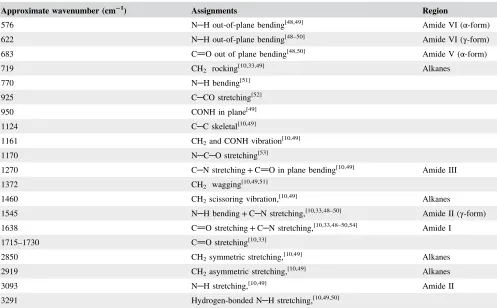
FTIR was used to analyze chemical changes during the plasma exposure. Figure 4 shows one FTIR spectrum of each sample of the tested materials: nontreated PA12 powder and the treated ones (1, 2, and 3 h exposures). The major absorption bands appeared in the FTIR spectra of the PA12 samples as listed in Table 2. All of these bonds and their assignments are based on previous studies.[10,33,48–54]As noted in Table 2 and Figure 4, the main functional groups are N─H groups (bending and
stretching), carbonyl groups (carbon-oxygen double bonded), single bonded carbon-carbon groups, and alkane groups (CH2).
Further, two bonds representing the α-phase of PA12 were
observed at wavenumber of 576 and 683 cm−1belonging to
[image:7.594.45.550.62.135.2]N─H and CO respectively.[48]These two bonds, however,
TABLE 1 Percentage change of density and volume of PA 12 powder with LP-PT treatment time
Weight of each sample: 0.3 gram Untreated PA12 1 h treated PA12 Change % 2 h treated PA12 Change %
Density g cm−3 1.0366 g cm−3 1.0677 g cm−3 +3.00 1.0694 g cm−3 +3.164
Standard deviation (Density) 0.0050 g cm−3
0.0027 g cm−3
0.0023 g cm−3
Volume cm3 0.2894 cm3 0.2810 cm3 −2.903 0.2805 cm3 −3.075
[image:7.594.128.465.620.714.2]Standard deviation (Volume) 0.0014 cm3 0.0007 cm3 0.0006 cm3
were not clearly distinguished, as the N─H band showed very
low intensity and the CO band was observed as a shoulder of
the bond of CH2at 719 cm−1.γ-phase was also observed at two
absorption lines of 622 cm−1 (N
─H) and 1545 cm−1 (N─H
bending + C─N stretching).[48]The entire FTIR spectral range
in Figure S6 displays all the fingerprint and Amide regions. Limited spectral changes between the treated and non-treated PA12 samples were found in FTIR data as displayed in Figure 4. The main reason for this, is that the depth of the chemical changes during plasma exposure is mostly limited to the topmost few atomic layers of the surface whereas the FTIR probes 1μm beneath the tested surface.[10] Moisture
may also affect the FTIR signal during specimen analy-sis.[10,33]Hence, all the PA12 samples were examined three times, mean values were calculated and shown in Table 3.
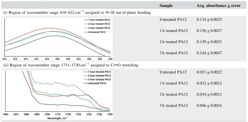
The FTIR results in Table 3 reveals spectral changes in two absorption bands (618–622 cm−1and 1715–1730 cm−1), confirming that surface chemical changes occurred on plasma treated surfaces. The intensity of the absorption bond at 618–
622 cm−1in Table 3(i) increased with the plasma exposure
time indicating the proportion of γ crystalline phase
increased.[33,50] As increased γ crystalline phase results in
toughened PA12, this suggests that the LP-PT can lead to enhanced toughness in PA12 sintered parts. The FTIR data in Table 3(ii) also confirms that absorption in the range of 1715–1730 cm−1, belonging to carbonyl groups, was
increased to 0.032, 0.034, and 0.046 after plasma exposure
of 1, 2, and 3 h respectively. Increased carbonyl (CO)
absorption indicates the presence of oxygenic species on the treated surfaces, confirming the earlier hypothesis of regarding the creation of oxygen species during plasma treatment.[33]
3.5
|
Pores formation in powder due to LP-PT
(SEM and HSM analyses)
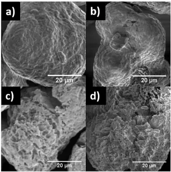
[image:8.594.49.546.59.367.2]A comparison between the nontreated PA12 and treated PA12 (1, 2, and 3 h) was made using SEM, images shown in Figure 5a-d. No significant changes were observed between powders from nontreated PA12 and 1 h treated PA12 except small holes appeared in the 1 h etched PA12 without any visible cracks (see Figure 5a and b). After 2 h of plasma treatment however, visible cracks and pores were easily observed in the particles, as shown in Figure 5c. These effects extended with prolonged plasma exposure of 3 h, as can be seen in Figure 5d, in which the particles are strongly affected by the plasma treatment leading to a more porous structure. Longer plasma treatments (2 and 3 h) have shown another beneficial effect of splitting the large agglomerates (non-sintered particles stuck to each other) into smaller particles as shown in Figure S7. It is believed that this effect is a result of chemical effect catalyzed by a low intensity ion bombardment causing atoms and molecules to be ejected from the particle surface.[55]
TABLE 2 Major FTIR absorption bands and their assignments of PA12
Approximate wavenumber (cm−1) Assignments Region
576 N─H out-of-plane bending[48,49] Amide VI (α-form)
622 N─H out-of-plane bending[48–50] Amide VI (γ-form)
683 CO out of plane bending[48,50] Amide V (α-form)
719 CH2 rocking[10,33,49] Alkanes
770 N─H bending[51]
925 C─CO stretching[52]
950 CONH in plane[49]
1124 C─C skeletal[10,49]
1161 CH2and CONH vibration[10,49]
1170 N─C─O stretching[53]
1270 C─N stretching + CO in plane bending[10,49] Amide III
1372 CH2 wagging[10,49,51]
1460 CH2scissoring vibration,[10,49] Alkanes
1545 N─H bending + C─N stretching,[10,33,48–50] Amide II (γ-form)
1638 CO stretching + C─N stretching,[10,33,48–50,54] Amide I
1715–1730 CO stretching[10,33]
2850 CH2symmetric stretching,[10,49] Alkanes
2919 CH2asymmetric stretching,[10,49] Alkanes
3093 N─H stretching,[10,49] Amide II
For a better understanding of the dual effect of LP-PT on the PA12 powder, hot stage microscopy (HSM) was used in which the powders were cooled followed by heating to 250 °C. Images taken during crystallization (cooling process) in HSM of 3 h plasma treated PA12 powder, showed a spherulitic structure consisting of stacks of parallel lamellae embedded in amorphous regions (exam-ples marked by arrows in Figure 6a). The lamellar morphology shown by HSM can be linked to SEM images after a prolonged plasma process, shown in Figure 6b. The region of interest marked in Figure 6a and b shows that the material loss which was predominantly from the intermedi-ate (amorphous regions).[56] This phenomenon can be observed in many particles as shown in Figure 5c and d. Thus, it confirms that there is a greater ratio of crystalline to amorphous material in the etched powder in comparison to the unprocessed powder, which is also suggested by density and FTIR measurements.
4
|
PARTS FABRICATED FROM
PLASMA TREATED POWDERS
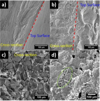
Treated (1 and 2 h) and nontreated powders were fabricated into parts via a Downward Heat Sintering method (DHS) which was shown in previous work to be a good indicator of Laser Sintering.[9] DHS is used here to determining the optimal parameters (temperature and time) for establishing the printability of PA12 powders. SEM micrographs of the cross section and top surface morphologies are displayed in
Figure 7a-c. The nontreated powders were entirely molten, showing a smooth top surface and homogeneous fracture in the range of temperature 185–195 °C as shown in Figure 7a. The treated powders (1 and 2 h), on the other hand, showed a heterogeneity on the top surface, as well as unmelted particles, as observed in Figure 7b and c. This may be attributed to the incorporation of new functionalities at the particles surface due to the plasma and UV radiation exposure, which was confirmed by the FTIR analysis in the previous sections. This suggests that the LP-PT had succeeded in altering the physical and chemical properties of PA12 by creating new functional groups, a wettable powder and a porous structure. However, the problem of the unmelted particles increases when the treated powder is subjected to melting conditions replicating those of laser sintering. The LS technique failed to fuse all the particles from the nontreated powders[57](see Figure 7d) especially with aged powder (recovered powder) which was thermally degraded during subsequent LS processes.[58]
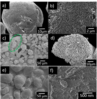
Hence, to obtain any benefit from plasma treatment in Laser sintered parts, a shorter exposure time is required. Therefore, the same batch of powder was subjected to two types of PJ higher power −K-APPJ for 1 and 3 min and
[image:9.594.43.554.56.308.2]lower power H-APPJ for 6 min. SEM was used to study the morphological changes on these particle surfaces as shown in Figure 8a-f. The SEM showed that at 1 min duration with the K-APPJ has made few micro-holes and porous structure as can be seen in Figure 8a and b respectively of similar size to that of LP-PT for 1 h. For a 3 min exposure to K-APPJ, many of the particles became fused together creating one
TABLE 3 FTIR absorption bands of PA12
Sample Avg. absorbance ± error
(i) Region of wavenumber range 618–622 cm−1
assigned to N─H out-of-plane bending
Untreated PA12
1 h treated PA12
2 h treated PA12
3 h treated PA12
0.134 ± 0.0023
0.136 ± 0.0027
0.139 ± 0.0023
0.144 ± 0.0047
(ii) Region of wavenumber range 1715–1730 cm−1
assigned to CO stretching
Untreated PA12
1 h treated PA12
2 h treated PA12
3 h treated PA12
0.021 ± 0.0022
0.032 ± 0.0012
0.034 ± 0.0012
sintered part (see green circle in Figure 8c) and while the small pores within particles became bigger and similar in size to 2–3 h of LP-PT. Figure 8e and f) shows the lower power H-APPJ 6 min treatment and shows no particle fusing, and a nano-porous structure. Figure S8 additionally compares the morphology of the LP-PT and H-APPJ for 6 min. It can be clearly seen that the LP-PT for 6 min hardly changes the PA12 surface whilst the H-APPJ 6 min treatment induces the above-mentioned porosity.
[image:10.594.128.467.47.387.2]Hence, the atmospheric pressure plasma jets K-APPJ and H-APPJ both change the surface morphology of PA12 particles whilst maintaining meltability (Figure 8c). Moreover, the plasma jet treated powder is perhaps wettable due to increasing the porosity.[59] However, the extent to the PA12 surface change is dependent on the PJ and further works are required on this as well as the chemical properties of the K-APPJ and H-APPJ treated powder.
FIGURE 5 High magnification SEM images of (a) PA12 without LP-PT plasma treatment (b) 1 h LP-PT treated PA12, (c) 2 h LP-PT treated PA12, and (d) 3 h LP-PT treated PA12
[image:10.594.134.467.577.702.2]5
|
CONCLUSIONS
Here we studied the effects of plasma treatment on the sintering of PA12 using different plasma techniques: low pressure air plasma treatment (LP-PT) and two atmospheric pressure plasma jets K-APPJ and H-APPJ.
Our results showed that the physical and chemical properties of LP-PT treated PA12 powder were altered. PA12 powder became wettable, denser, and porous which results from the incorporation of oxygen groups, dissociation of carbon bonds with the accompanied removal of volatile products and amorphous components. Besides the usefulness of using LP-PT for producing wettable and porous structured powder, the melting properties of the LP-PT treated PA12 powder needs to be considered if powders are intended for the fabrication of parts by Laser Sintering. Prolonged low pressure plasma treatment resulted in poor melting behavior in the time needed to generate target morphological changes. K-APPJ and H-APPJ, on the other hand, have rapidly created porous structures for K-APPJ similar to that of LP-PT for 2–3 h. Moreover, the short K-APPJ has not prevented the meltability of the PA12 powder but the rapid pore formation and melting make it difficult to control. Due to the lower
power, the H-APPJ was deemed the more useful treatment to observe the morphology change induced by the atmospheric Plasma jet.
Hence, we conclude that for Laser sintering applications of PA12 powder, PJ treatment technique is recommended. However, further work on characterizing the chemical and physical changes of K-APPJ and H-APPJ treated PA12 using techniques such as FTIR and wettability analyses will be required. This testing is important to discover whether the shorter minute exposures have made similar chemical and physical changes to the LP-PT or not.
ACKNOWLEDGMENTS
[image:11.594.130.467.49.388.2]Alaa Almansoori thanks the Ministry of Higher Education and Scientific Research in Iraq and its representative in the UK, Iraqi cultural attaché in London for financial support. Cornelia Rodenburg and Kerry Abrams thank the Engineer-ing and Physical Sciences Research Council (EPSRC) for funding under EP/N008065/1. C. Rodenburg, K. Abrams, J. Schäfer, and T. Gerling thank the Royal Society for funding under the international exchanges program IE160969. We also thank Wendy Birtwistle (Center for Advanced Additive
Manufacturing), and Qwan Wan and staff of the Sorby Center for Electron Microscopy and Microanalysis and acknowledge their support. T. Gerling further thanks the German Ministry of Education and Research (BMBF) for funding under 13N11188. The authors thank neoplas GmbH for providing the plasma source kINPen (www.neoplas.eu).
ORCID
Alaa Almansoori http://orcid.org/0000-0002-9757-7724
Robert Masters http://orcid.org/0000-0001-7457-1955
Kerry Abrams http://orcid.org/0000-0002-2789-7204
Jan Schäfer http://orcid.org/0000-0002-0652-5057
Torsten Gerling http://orcid.org/0000-0002-5184-257X
Candice Majewski http://orcid.org/0000-0003-3324-3511
Cornelia Rodenburg http://orcid.org/0000-0002-9590-375X
REFERENCES
[1] Z.-X. Low, Y. T. Chua, B. M. Ray, D. Mattia, I. X. Metcalfe, D. A. Patterson,J. Memb. Sci.2017,523, 596.
[2] M. Pavan, T. Craeghs, R. Verhelst, O. Ducatteeuw, J.-P. Kruth, W. Dewulf,Case Stud. Nondestr.Test. Eval.2016,6, 62.
[3] Y. Khalil, A. Kowalski, N. Hopkinson,Addit. Manuf.2016,10, 67. [4] A. Warnakula, S. Singamneni,Materials2017,10, 864. [5] R. D. Goodridge, C. J. Tuck, R. J. M. Hague,Prog. Mater. Sci.
2012,57, 229.
[6] G. M. Vasqueza, C. E. Majewski, B. Haworth, N. Hopkinson,
Addit. Manuf.2014,1-4, 127.
[7] U. Ajoku, N. Hopkinson, M. Caine, Mater. Sci. Eng. A2006,
428, 211.
[8] A. Almansoori, C. Majewski, C. Rodenburg,JOM2017,69, 2278. [9] A. Almansoori, R. Seabright, C. Majewski, C. Rodenburg,IOP
Conf. Ser.2017,195, 012003.
[10] J. Hnilica, L. Potočnáková, M. Stupavská, V. Kudrle,Appl. Surf. Sci.2014,288, 251.
[11] R. Puffr, V. Kubanek, Lactam-based Polyamides, Volume I:
Polymerization Structure. CRC Press, Boca Raton, FL1991.
[12] L. Bao, H. Fan, Y. Chen, J. Yan, T. Yang, Y. Guob,RSC Adv.2016,
6, 99346.
[13] P. Slepička, N. Slepičková Kasálková, E. Stránská, L. Bačáková,
V.Švorčík,Express Polym. Lett.2013,7, 535.
[14] M.Šíra, D. Trunec, P St'ahel, V. Buršíková, Z. Navrátil,J. Phys. D:
Appl. Phys.2008,41, 015205.
[image:12.594.129.467.45.392.2][15] Z. Gao, J. Sun, S. Peng, L. Yao, Y. Qiu,Appl. Surf. Sci.2009,256, 1496.
[16] P. Kruger, R. Knes, J. Friedrich. Surf Coat Technol 1999, 12, 240e4.
[17] K. Fricke, I. Koban, H. Tresp, L. Jablonowski, K. Schroder, A. Kramer, K.-D. Weltmann, T. von Woedtke, T. Kocher,PLoS ONE
2012,7, e42539.
[18] R. Morent, N. D. Geyter, J. Verschuren, K. D. Clerck, P. Kiekens, C. Leys,Surf. Coat. Technol.2008,202, 3427.
[19] K. Fricke, H. Steffen, T. von Woedtke, K. Schröder, K.-D. Weltmann,Plasma Process. Polym.2011,8, 51.
[20] J. Schäfer, K. Fricke, F. Mika, Z. Pokorná, L. Zajíčková, R. Foest,
Thin Solid Films2017,630, 71.
[21] U. Lommatzsch, D. Pasedag, A. Baalmann, G. Ellinghorst, H.-E. Wagner,Plasma Process. Polym.2007,4, S1041.
[22] J. Hanusová, D. Kováčik, M. Stupavská, M. Černák, I. Novák,
Open Chem.2015,13, 382.
[23] A. Dupuis, T. H. Ho, A. Fahs, A. Lafabrier, G. Louarn, J. Bacharouche, A. Airoudj, E. Aragon, J.-F. Chailan,Appl. Surf. Sci.
2015,357, 1196.
[24] Y. Kim, Y. Lee, S. Han, K.-J. Kim, Surf. Coat. Technol.2006,
16-17, 4763.
[25] C. K. Akkan, M. E. Hammadeh, A. May, H.−W Park, H. Abdul-Khaliq, T. Strunskus, O. C. Aktas,Lasers Med. Sci.2014,29, 1633. [26] J. M. Grace, L. J. Gerenser,J. Dispersion Sci. Technol.2003,24,
305.
[27] D. Breite, M. Went, A. Prager, A. Schulze,Polymers2015,7. [28] Y. Chang, C.-Y. Ko, Y.-J. Shih, D. Quémener, A. Deratani, T-C.
Wei, D.-M. Wang, J.-Y. Lai,J. Memb. Sci.2009,345, 160. [29] B. V. d. Bruggen,J. Appl. Polym. Sci.2009,114, 630.
[30] K. Matsubara, M. Danno, M. Inoue, H. Nishizawa, Y. Honda, T.
Abe,Appl. Surf. Sci.2013,284, 340.
[31] S.-W. Ha, R. Hauert, K.-H. Ernst, E. Wintermantel,Surf. Coat.
Technol.1997,96, 293.
[32] L. Zhou, Y. Qian, Y. Zhu, H. Liu, K. Gan, J. Guo,Dent. Mater.
2014,30, e209.
[33] I. Novák, M.Števiar, I. Chodák,Monatsh. Chem.2006,137, 943. [34] P. Lennon, E. Espuche, H. Sautereau, D. Sage,Int. J. Adhes. Adhes.
1999,19, 273.
[35] F. Dreux, S. Marais, F. Poncin-Epaillard, M. Metayer, M. Labbe, J.-M. Saiter,Mat. Res. Innovations2003,7, 183.
[36] D. Pavliňák, J. Hnilica, A. Quade, J. Schäfer, M. Alberti, V. Kudrle,
Polym. Degrad. Stab.2014,108, 48.
[37] D. Cheneler, J. Bowen,Soft Matter2013,9, 344.
[38] P. Groning, M. C. Coen, L. Schlapbach,Chimia2001,55, 171. [39] C. Canal, R. Molina, E. Bertran, P. Erra,J. Adhesion Sci. Technol.
2004,18, 1077.
[40] K. Wudy, D. Drummer, M. Drexler,AIP Conf. Proc.2014,1593, 702. [41] L. Verbelen, S. Dadbakhsh, M. V. d. Eynde, J.-P. Kruth, Eur.
Polym. J.2016,75, 163.
[42] L. Ming, H. Yang, W. Zhang, X. Zeng, D. Xiong, Z. Xu, H. Wang, W. Chen, X. Xu, M. Wang, J. Duan, Y.-B. Cheng, J. Zhang, Q. Bao, Z. Wei, S. Yang,J. Mater. Chem. A2014,2, 4566.
[43] F. Lin, Master of Applied Science Thesis, University of Waterloo, Canada,2006.
[44] A. Dupuis, F-X. Perrin, A. U. Torres, J-P. Habas, L. Belec, J-F. Chailan,Polym. Degrad. Stab.2017,135, 73.
[45] R. C. Masters, Q. Wan, Y. Zhou, A. M. Sandu, M. Dapor, H. Zhang, D. G. Lidzey, C. Rodenburg,J. Phys. Conf. Ser.2015,644, 012017.
[46] J. M. Goddard, J. H. Hotchkiss,Prog. Polym. Sci.2007,32, 698. [47] K. Novotna, M. Bacakova, N. S. Kasalkova, P. Slepicka, V. Lisa,
V. Svorcik, L. Bacakova,Materials2013,6, 1632.
[48] S. Rhee, J. L. White,J. Polym. Sci. Part B Polym. Phys.2002,40, 1189.
[49] J. Han, Z. Cao, W. Gao,J. Mater. Chem. A2013,1, 4941. [50] R. Rafiq, D. Cai, J. Jin, M. Song,Carbon2010,48, 4309. [51] N. Vasanthan,J. Chem. Educ.2012,89, 387.
[52] M. Porubská, O. Szöllős, A. Kóňová, I. Janigová, M. Jašková, K. Jomová, I. Chodák,Polym. Degrad. Stab.2012,97, 523. [53] J. Maillo, P. Pages, E. Vallejo, T. Lacorte, J. Gacén,Eur. Polym. J.
2005,41, 753.
[54] A. H. Kuptsov, G. N. Zhizhin,Handbook of Fourier Transform
Raman and Infrared Spectra of Polymers. Elsevier, Amsterdam
1998. Vol.45.
[55] P. K. Chu, J. Y. Chen, L. P. Wang, N. Huan,Mater. Sci. Eng. R
2002,36, 143.
[56] Q. Guo,Polymer Morphology: Principles, Characterization, and
Processing. John Wiley & Sons, USA2016.
[57] N. Hopkinson, C. E. Majewski, H. Zarringhalam, CIRP Ann.
Manuf. Technol.2009,58, 197.
[58] K. Wudy, D. Drummer, K. Kühnlein, M. Drexler,AIP Conf. Proc.
2014,1593, 691.
[59] S. Mane, S. Ponrathnam, N. Chavan,Can. Chem. Trans.2015,3, 473.
SUPPORTING INFORMATION
Additional supporting information may be found online in the Supporting Information section at the end of the article.