Int. J. Electrochem. Sci., 7 (2012) 10054 - 10062
International Journal of
ELECTROCHEMICAL
SCIENCE
www.electrochemsci.org
Typical Rare Earth Doped Lead Dioxide Electrode: Preparation
and Application
Dai qizhou, Shen Hong, Xia Yijing, Chen Jianmeng*
College of Biological & Environmental Engineering, Zhejiang University of Technology, Hangzhou 310032, Zhejiang, China
*
E-mail: [email protected]
Received: 22 July 2012 / Accepted: 3 August 2012 / Published: 1 October 2012
Typical rare earth doped lead dioxide electrode (Ti/SnO2-Sb2O3/PTFE-La-β-PbO2) was prepared by
the thermal decomposition electrodeposition technique for the treatment of simulated wastewater containing toluene sulfonic acid (TSA). Under the conditions of initial quality concentration of p-TSA 500mg·L-1, current density 30mA·cm-2
, pH 2 and room temperature, after 3 hours degradation, the removal rates of p-TSA, COD and TOC arrived 96.05%, 59.40% and 38.00% for Ti/Sb-SnO2/PTFE-La-β-PbO2. The results showed that the rare earth doped electrode could cover the
advantages both catalytic efficiency and stability. What’s more, based on the electrode structure analysis of XRD and SEM, the modified mechanism of La doped was also proposed, which would be helpful for rare earth application in wastewater pollution control.
Keywords: electrocatalysis; typical rare earth doped lead dioxide electrode; p-toluene sulfonic acid; La
1. INTRODUCTION
Highly concentrated pharmaceutical wastewater was a challenge of environmental concern for the large emission, the high concentration of organic and the poor biodegradability. Traditional treatment technologies, such as biological, physical and chemical treatment could not meet the demand of increasingly strict discharge standard. Therefore, alternative way, including ozonation oxidation [1], photochemical [2] and peroxide/UV [3] treatment, etc, had been researched for the pharmaceutical wastewater treatment was an urgent demand for the environmental workers and the government [4-6]. The choice of treatment also depends on economics as well as ease of control, reliability and efficiency of the treatment.
environmental friendly process, had been applied among many different fields of environmental pollution treatments [7-9]. Numerous electrode materials could be used to oxidize organic wastes. But, in traditional electrochemical oxidation system, especially for the degradation of high concentration organic wastewater, oxidation or reduction on electrode surface would produce a polymer film, which resulted in low electrode activity and high power consumption [10, 11]. Therefore, the electrode materials and the electrolysis conditions should to be improved, for high effective and economical degradation. Electrode was known as the “core” of electrochemical oxidation system. Therefore, BDD and various metal oxides film electrodes, e.g., PbO2, SnO2 and RuO2 had been studied [12-14]. Since
the discovery of dimensionally stable anodes (DSA) nearly 30 years ago [15], there had been a successful development about DSA electrode, and much researches had also been done on finding and preparing new DSA anodes for high stability, high activity and low cost of electrodes. Among them, PbO2 electrode was treated as an excellent one owing to its lower price, chemical stability and high
overpotential for the oxygen evolution reaction. What’s more, PbO2 anode could also be
electrogenerated both in acidic [16, 17] and alkaline solutions containing Pb2+ ions [18]. The electrodeposition process mainly involved the following stages [17]:
+
-2 ads
H OOH +H +e (1)
2+ 2+
ads
Pb +OH Pb(OH) (2)
2+ +
-2 2
Pb(OH) +H OPbO +3H +e (3)
In this work, considering the rare earth with special 4f electronic structure [7, 19, 20], a typical rare earth doped lead dioxide electrode prepared by thermal decomposition electrodeposition technique was used for the treatment of simulated wastewater containing p-toluene sulfonic acid (p-TSA). Different doped moral ratios of rare earth had also been discussed for the optimal one. Chemical oxygen demand (COD) and total organic carbon (TOC) were tested to value the degradation efficiency of the Ti/SnO2-Sb2O3/PTFE-La-β-PbO2 electrode. Finally, based on the results of scanning electron
microscope (SEM) and X-ray diffraction (XRD), the modified mechanism of La doped was proposed, which would be helpful for rare earth application in wastewater pollution control.
2. MATERIALS & METHODS 2.1 Materials
2.2 The structure of electrode
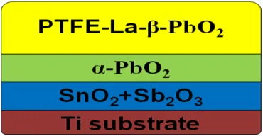
The typical rare earth doped lead dioxide electrode (Ti/SnO2-Sb2O3/PTFE-La-β-PbO2) was
composed by four layer (Ti substrate, SnO2+Sb2O3 layer, α-PbO2 layer and PTFE-La-β-PbO2 layer).
[image:3.596.206.391.176.272.2]The profile chart of electrode was shown as Fig.1.
Figure 1. The profile chart of Ti/SnO2-Sb2O3/PTFE-La-β-PbO2 electrode
2.3 Preparation of electrodes
Ti/SnO2-Sb2O3 electrodes, which were prepared through the thermal decomposition method,
were used as the substrates for the electrodeposition of PbO2 films. And, the PbO2 films were
composed by α-PbO2 layer and β-PbO2 layer. The electrodeposition of α-PbO2 layer was prepared by
the electrolyte contained 4~5 mol·L-1 NaOH and 0.1 mol·L-1 PbO, and performed with a current density of 4~5 mA·cm-2 for 60 min at a temperature of 60 ºC. Then, the electrolyte for electrodeposition of β-PbO2 was composed of 0.4~0.6 mol·L-1 Pb(NO3)2, 0.1~0.2 mol·L-1 KF·2H2O,
4mL·L-1 polytetrafluororethlene (PTFE 60wt%), and the pH was adjusted to 1.68 with HNO3. Rare
earth oxides (lanthanum oxide, La2O3), were added into the solution and dispersed in an ultrasonic bath
for 15 min before electrodeposition, which plated under the current density of 4~5 mA·cm-2 for 120 min at a temperature of 80 ℃. Finally, Ti/SnO2-Sb2O3/PTFE-β-PbO2 and Ti/SnO2-Sb2O3
/PTFE-La-β-PbO2 electrodes were rinsed with deionized water.
2.4 Methods
ray diffractometer (X’Pert PRO, PNAlytical, Netherlands) was used to analyze the crystalline structure of the films.
3. RESULTS & DISCUSSION
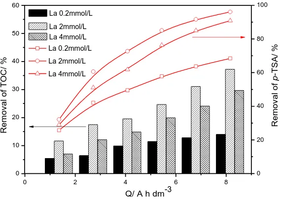
3.1 The different La molar concentrations
0 2 4 6 8
0 20 40 60 80 100
Q/ A h dm-3
R e mo v a l o f p -T S A / % La0.2mmol/L La2mmol/L La4mmol/L 0 10 20 30 40 50 60 R e mo v a l o f T OC / % La 0.2mmol/L La 2mmol/L La 4mmol/L
Figure 2. Removal rates of p-TSA and TOC by different molar concentration of La doped Ti/SnO2
-Sb2O3 electrodes
The maximum rate of p-TSA removal of La-doped Ti/SnO2-Sb2O3 electrodes was achieved
[image:4.596.157.442.209.411.2]
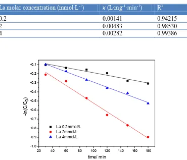
Table 1. Degradation kinetics constant (κ) of p-TSA removal by different molar concentration of La doped Ti/SnO2-Sb2O3 electrodes
La molar concentration (mmol·L-1
) κ (L·mg-1·min-1) R2
0.2 0.00141 0.94215
2 0.00483 0.98530
4 0.00282 0.99386
20 40 60 80 100 120 140 160 180
-1.0 -0.9 -0.8 -0.7 -0.6 -0.5 -0.4 -0.3 -0.2 -0.1
La 0.2mmol/L La 2mmol/L La 4mmol/L
-l
n(C
/C0
)
time/ min
Figure 3. Pseudo-first-order kinetics fit of p-TSA removal by different molar concentration of La doped Ti/SnO2-Sb2O3 electrodes
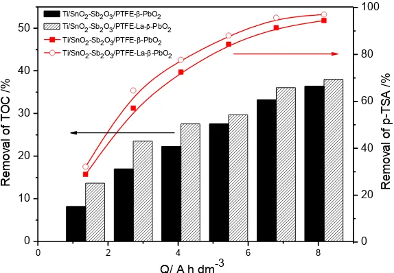
3.2 Degradation of p-TSA by different electrodes
A solution of 500 mg·L-1 of p-TSA of pH 2.0 was electrolyzed at 30 mA·cm-2 and with a room temperature to test its degradation efficiency by anodic oxidation with Ti/SnO2-Sb2O3/PTFE-β-PbO2
and Ti/SnO2-Sb2O3/PTFE-La-β-PbO2. Fig. 4 and 5 showed the removal rate of p-TSA, TOC, COD.
Doped with La could slightly improve the removal rates of p-TSA and TOC. As one of important indexes, removal rate of COD exhibited the ability of electrode to mineralize. The Ti/SnO2
-Sb2O3/PTFE-La-β-PbO2 anode has the higher COD removal of p-TSA (59.40%), compared with
Ti/SnO2-Sb2O3/PTFE-β-PbO2 electrode, whose COD removal is 46.50%. as shown in Fig. 5. Therefore,
Ti/SnO2-Sb2O3/PTFE-La-β-PbO2 electrode possessed excellent mineralization to target contaminant
(p-TSA), compared with undoped anode (Ti/SnO2-Sb2O3/PTFE-β-PbO2 electrode). Combined the
[image:5.596.113.483.104.421.2] [image:5.596.158.422.213.419.2]
Figure 4. Removal rates of p-TSA and TOC by Ti/SnO2-Sb2O3/PTFE-β-PbO2 and Ti/SnO2
-Sb2O3/PTFE-La-β-PbO2 electrodes
Figure 5. Removal rates of COD during the electrolysis by Ti/SnO2-Sb2O3/PTFE-β-PbO2 and
Ti/SnO2-Sb2O3/PTFE-La-β-PbO2 electrodes
3.3 Characterization of electrodes and analysis of doped mechanism
XRD and SEM were employed for characterize Ti/SnO2-Sb2O3/PTFE-β-PbO2 and Ti/SnO2
-Sb2O3/PTFE-La-β-PbO2 electrodes. The XRD spectrums and SEM images were shown in Fig. 6 and
Fig. 7, respectively. As can be seen in Fig. 6, compared with the PbO2 film of Ti/SnO2-Sb2O3
/PTFE-PbO2, there had no new mineral phases on the PbO2 film with the addition of La. This phenomenon can
be explained by the low amount of La or the solid solution composed by La2O3 and PbO2 for the
doping of La into the crystal lattice of PbO2 as a kind of replacement or interstitial material [21, 22]. 0 20 40 60 80 100
0 2 4 6 8
0 10 20 30 40 50 R emoval of TOC / %
Q/ A h dm-3 Ti/SnO2-Sb2O3/PTFE--PbO2
Ti/SnO2-Sb2O3/PTFE-La--PbO2
R emoval of p -TS A / %
Ti/SnO2-Sb2O3/PTFE--PbO2 Ti/SnO2-Sb2O3/PTFE-La--PbO2
0 2 4 6 8
0 10 20 30 40 50 60 R e mo va l o f C O D / %
Q/ A h dm-3
Ti/SnO2-Sb2O3/PTFE-La--PbO2
[image:6.596.157.444.94.293.2] [image:6.596.162.421.362.562.2]
Furthermore, the addition of La partially broadened the diffraction intensity of β-PbO2 on the film of
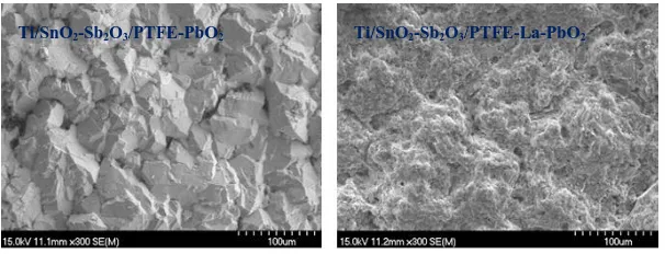
electrodes. That was because the introduction of La3+ (0.103nm), which had bigger ionic radius than Pb4+ (0.0775nm), expanded the crystal cell in the progress of doped [23]. What’s more, the morphology of Ti/SnO2-Sb2O3/PTFE-La-β-PbO2 electrodes, as shown in Fig. 7, was compact, uniform,
and presented a typical mushroom shaped. The comparison between the SEM image of Ti/Sb-SnO2/PTFE-β-PbO2 and that of Ti/SnO2-Sb2O3/PTFE-La-β-PbO2 electrode supported the speculation
from XRD visually. Little holes in the surface of Ti/SnO2-Sb2O3/PTFE-La-β-PbO2 electrode could help
improve the specific surface area of electrodes, exposed more active sites and promote the reaction mass transportation. The porous film of Ti/SnO2-Sb2O3/PTFE-La-β-PbO2 contributed to the ability of
electrocatalysis.
Figure 6. XRD spectrums of Ti/SnO2-Sb2O3/PTFE-β-PbO2 and Ti/SnO2-Sb2O3/PTFE-La-β-PbO2
electrodes
Figure 7. SEM images of Ti/SnO2-Sb2O3/PTFE-β-PbO2 and Ti/SnO2-Sb2O3/PTFE-La-β-PbO2
electrodes 4. CONCLUSION
Typical rare earth doped lead dioxide electrode (Ti/SnO2-Sb2O3/PTFE-La-β-PbO2) was
prepared by the thermal decomposition electrodeposition technique. It was can be proved that the
Ti/SnO2-Sb2O3/PTFE-PbO2 Ti/SnO2-Sb2O3/PTFE-La-PbO2
10 20 30 40 50 60 70
0 1000 2000 3000 4000 5000 6000
700010 20 30 40 50 60 70
0 1000 2000 3000 4000 5000 6000 7000
(101)
(301) (112)
(220) (211) (111)
(110)
Ti/SnO2-Sb2O3/PTFE--PbO2
2(o
)
cou
nts
[image:7.596.163.428.254.450.2] [image:7.596.149.452.521.637.2]
inference of co-doped with PTFE-La2O3 on the electrocatalytic properties of Ti/SnO2-Sb2O3
/PTFE-PbO2 was positive. La as a dopant brought remarkable promotion to the mineralization efficiency of
intermediates of p-TSA stimulated wastewater (With La bearing, the removal rates of COD and p-TSA during 3 h electrolysis at the current density of 30mA·cm-2 were 59.40% and 95.00%, respectively, with the instantaneous current efficiency being 49.22%-18.13%). What’s more, the rates of p-TSA removal were well fitted with first-order rate constants. According to SEM images and XRD spectrums, PTFE-La2O3 co-doped had advanced function on the promotion of electrocatalysis and the
modification of Ti/SnO2-Sb2O3/PTFE-β-PbO2 film structure. The porous film of Ti/SnO2-Sb2O3
/PTFE-La-β-PbO2 improved the specific surface area, exposed more active sites, promoted mass
transportation and enhanced the efficiency of electrocatalysis.
ACKNOWLEDGEMENTS
The authors are grateful for the financial support provided by the National Key Project of Scientific and Technical Supporting Programs Funded by Ministry of Science & Technology of China (No. 2011BAE07B09), the Natural Science Foundation of Zhejiang province (No. Y5090272), the Key Scientific Group of Zhejiang province (No. 2011R09048-04) and the Research Fund for the Doctoral Program of Higher Education of China (No. 20113317120004).
References
1. Z.Q. He, Q.L. Cai, F.Y. Hong, Z. Jiang, J.M. Chen, S. Song, Ind. Eng. Chem. Res., 51 (2012) 5662 2. C. Sirtori, A. Zapata, I. Oller, W. Gernjak, A. Agüera, S. Malato, Water Res., 43 (2009) 661 3. A.K. Biń, S. Sobera-Madej, Ozone-Sci. Eng., 34 (2012) 136
4. X.Y. Li, Y.H. Cui, Y.J. Feng, Z.M. Xie, J.D. Gu, Water Res., 39 (2005) 1972 5. B.K. Hordern, R.M. Dinsdale, A.J. Guwy, Water Res., 42 (2008) 3498
6. E. Gracia-Lor, J.V. Sancho, R. Serrano, F. Hernández, Chemosphere, 87 (2012) 453
7. J. Radjenovic, A. Bagastyo, R.A. Rozendal, Y. Mu, J. Keller, K. Rabaey, Water Res., 45 (2011) 1579
8. J.L. Cao, H.Y. Zhao, F.H. Cao, J.Q. Zhang, C.N. Cao, Electrochim. Acta, 54 (2009) 2595 9. S.P. Tong, C.A. Ma, H. Feng, Electrochim. Acta, 53 (2008) 3002
10.Y.J. Feng, Y.H. Cui, B. Logan, Z.Q. Liu, Chemosphere, 70 (2008) 1629 11.Y.H. Cui, Y.J. Feng, Z.Q. Liu, Electrochim. Acta, 54 (2009) 4903
12.B. Boye, E. Brillas, B. Marselli, P.A. Michaud, C. Comninellis, G. Farnia, G. Sandonà, Electrochim. Acta, 51 (2006) 2872
13.C.A. Martínez-Huitle, M.A. Quiroz, C. Comninellis, S. Ferro, A.De. Battisti, Electrochim. Acta, 50 (2004) 949
14.V.V. Panic, A.B. Dekanski, T.R. Vidaković, V.B. Mišković-Stanković, B.Ž. Javanović, V.Ž. Nikolić, J. Solid State Electrochem., 9 (2005) 43
15.H.B. Beer. US, Patent 3632498, (1972)
16.M.E. Hyde, R.M.J. Jacobs, R.G. Compton, J. Phys. Chem. B, 108 (2004) 6381
17.A.B. Velichenko, R. Amadelli, G.L. Zucchini, D.V. Girenko, F.I. Danilov, Electrochim. Acta, 45 (2000) 4341
18.D. Devilliers, M.T.Dinh Thi, E. Mahé, V. Dauriac, N. Lequeux, J. Electroanal. Chem., 573 (2004) 227
20.Y.H. Cui, Y.J. Feng, X.Y. Li, Chem. Eng. Technol., 34 (2011) 265 21.Y. Yang, J.M. Zhang, Chin. J. Environ. Eng., 3 (2009) 893