City, University of London Institutional Repository
Citation
:
Arnold, P. (2018). Hybrid Radio Resource Management with Limited Channel Feedback Information in Relay enhanced OFDMA Networks. (Unpublished Doctoral thesis, City, University of London)This is the accepted version of the paper.
This version of the publication may differ from the final published
version.
Permanent repository link:
http://openaccess.city.ac.uk/22229/Link to published version
:
Copyright and reuse:
City Research Online aims to make research
outputs of City, University of London available to a wider audience.
Copyright and Moral Rights remain with the author(s) and/or copyright
holders. URLs from City Research Online may be freely distributed and
linked to.
Hybrid Radio Resource Management with Limited
Channel Feedback Information in Relay enhanced
OFDMA Networks
Paul Arnold
Doctor of Philosophy
School of Mathematics, Computer Science and Engineering, City, University of London
Contents
Acronyms XIII
1 Introduction 1
1.1 Motivation and Overview . . . 1
1.1.1 Objectives statement . . . 2
1.2 Contribution of the Thesis . . . 3
1.3 Thesis structure and content . . . 4
2 Relay extended OFDMA Networks 6 2.1 Network architecture in 3GPP . . . 6
2.1.1 Core network . . . 6
2.1.2 Radio access network . . . 7
2.1.3 New study item for 3GPP Release 15/16 revisiting relay nodes . . 9
2.2 Relay types in 3GPP . . . 10
2.2.1 Enabling Time Division Multiplexing (TDM) for half duplex RNs in 3GPP . . . 15
2.2.2 Full duplex and Half duplex relay operation mode . . . 17
2.2.3 Radio channel feedback . . . 18
2.2.4 Fixed relay deployment scenarios and commercial aspects . . . . 20
2.3 Radio resource management in RN extended heterogeneous mobile net-works . . . 21
2.3.1 Capacity of mobile networks . . . 22
2.3.2 Problem formulation . . . 25
2.3.3 Level of centralization and signalling overhead for RRM schemes 28 2.3.4 Inter Cell Interference Coordination . . . 33
2.3.5 Buffer aided RN . . . 37
2.3.7 Radio resource scheduler . . . 39
2.4 Summary . . . 50
2.5 Research problem . . . 52
3 Methodology 54 3.1 System level simulation processing chain . . . 55
3.1.1 Input parameter . . . 57
3.1.2 Initialization . . . 57
3.2 Scenario loop . . . 59
3.2.1 Pre-Processing . . . 59
3.2.2 Scenario initialization . . . 59
3.3 Snapshot loop . . . 65
3.3.1 Event control . . . 65
3.3.2 RRM update . . . 65
3.3.3 Scheduler update . . . 65
3.3.4 SINR calculation . . . 66
3.3.5 Analysis update . . . 68
3.3.6 Channel update . . . 68
3.4 Definition of the key performance indicators . . . 69
3.4.1 User Geometry (wideband SINR) . . . 70
3.4.2 SINR calculation . . . 70
3.4.3 Fairness (Normalized user throughput) . . . 71
3.4.4 User throughput . . . 72
3.5 Implementation of relay nodes . . . 73
3.5.1 Site planning approach . . . 73
3.5.2 Different link types . . . 74
3.5.3 MBSFN subframe configuration . . . 75
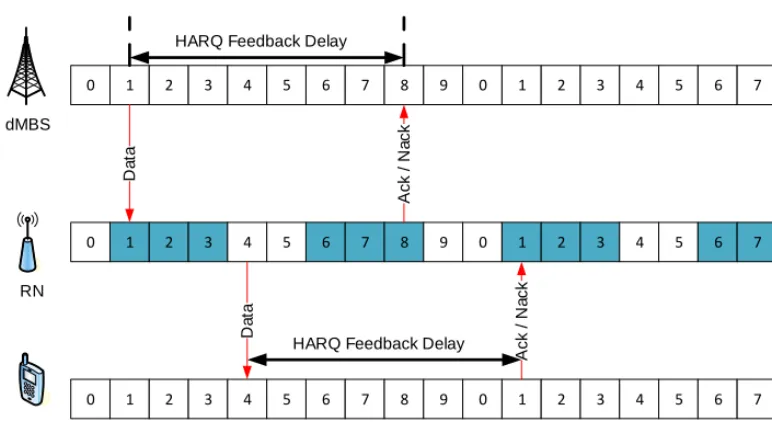
3.5.4 Channel feedback delay and HARQ timing . . . 75
3.5.5 Buffer structure for the two-hop transmission . . . 79
3.5.6 Scheduler for relay enhanced networks . . . 80
3.6 Calibration . . . 81
4 Design of the effective hybrid RRM scheme 87
4.1 Scenario description . . . 88
4.2 Adapted decentralized MS cell selection procedure . . . 91
4.3 Network-centralized asynchronous RRM . . . 92
4.3.1 Simplified numerical example for the centralized optimization pro-cess . . . 93
4.3.2 Heuristic approach . . . 97
4.4 Cell-centralized synchronous adapted scheduling . . . 109
4.4.1 Scheduling strategies for optimized subbands . . . 115
4.4.2 Numerical examples for the two-Hop proportional fair metric . . 117
4.5 Additional signalling and overhead consideration . . . 122
4.6 Summary . . . 124
5 Performance analysis 126 5.1 Assumptions of the network scenario . . . 127
5.2 Studies of important aspects in RN extended networks . . . 130
5.2.1 Comparison of different cell selection metrics . . . 130
5.2.2 Comparison of exclusive backhaul scheduling and co-scheduling . 132 5.3 Final results of the hybrid radio resource management scheme . . . 133
5.3.1 Throughput comparison of different two-hop MS feedbacks for-warded from RN to MBS . . . 134
5.3.2 Throughput comparison with different fitness functions and schedul-ing policies . . . 135
5.3.3 Final comparison for best feedback, power reduction pattern and scheduling settings . . . 138
5.3.4 SINR comparison for best settings . . . 139
5.3.5 Fairness comparison for best settings . . . 141
5.3.6 Energy consumption . . . 142
6 Conclusions and outlook 143 6.1 Conclusions . . . 143
6.2 Future work . . . 144
List of Tables
2.1 Summary of further RN type attributes . . . 14
2.2 Advantages and Disadvantages of the Radio Resource Management (RRM) centralization level . . . 33
2.3 Summary RN RRM design principles . . . 51
3.1 Relay planning gain . . . 74
3.2 MBSFN subframe patterns (from a to h) and their periodicity . . . 75
3.3 An example of an MBSFN assignment for 2 RNs . . . 76
3.4 Requirements for investigations of Relay Node (RN) extended large scale network performance . . . 85
4.1 Summary of the required additional feedback information for the hybrid RRM scheme . . . 123
List of Figures
1.1 Principle flow chart of the SLS with respect to the hybrid RRM scheme
and its decomposed sub-problems . . . 5
2.1 EPC Core Architecture [6, 7] . . . 7
2.2 LTE-Advanced RAN Architecture with RN [9] . . . 8
2.3 NG RAN Architecture [12] . . . 9
2.4 NG RAN gNB Architecture [13] . . . 9
2.5 A heterogeneous network consists of wireline backhauled macro, pico, femto, cells and wireless backhauled RN . . . 11
2.6 Defined interfaces for RN extended mobile networks by the Third Gener-ation Partnership Project (3GPP) . . . 11
2.7 Layer 1 RN Protocol Stack . . . 12
2.8 Layer 2 RN Protocol Stack . . . 13
2.9 Layer 3 RN Protocol Stack . . . 13
2.10 Downlink half duplex RN radio link operation . . . 16
2.11 Use of MBSFN subframe structure to receive data at the RN . . . 16
2.12 Full Duplex vs. Half Duplex transmission . . . 18
2.13 Fixed RN Deployment Scenarios . . . 20
2.14 Link types for an RN-extended Network . . . 24
2.15 Downlink resource grid in LTE [47] . . . 27
2.16 Level of RRM centralization and corresponding feedback requirement for FDD downlink . . . 29
2.17 Level of RRM centralization and corresponding feedback requirement for TDD . . . 29
2.18 Example Fractional Frequency Reuse Patterns . . . 35
2.19 MS specific buffer structure at the RN . . . 38
2.21 Radio channel dependent scheduling . . . 42
2.22 Max SINR scheduling . . . 43
2.23 Two hop proportional fair scheduling . . . 45
2.24 Two hop co-scheduling among directly attached UEs and RNs . . . 47
3.1 DT System Level Simulator Block Diagram . . . 56
3.2 Standard network layout with two rings of MBS sites with three sectors . 58 3.3 Wrap around technique to prevent border effects . . . 58
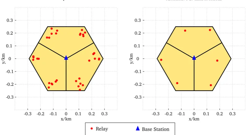
3.4 Two randomly distributed relays per sector . . . 60
3.5 1/3 randomly dropped, 2/3 user hot zone distribution . . . 61
3.6 User Geometry for an MBS/RN Scenario during RN receiving mode . . . 63
3.7 User Geometry for a MBS/RN Scenario during RN sending mode . . . . 64
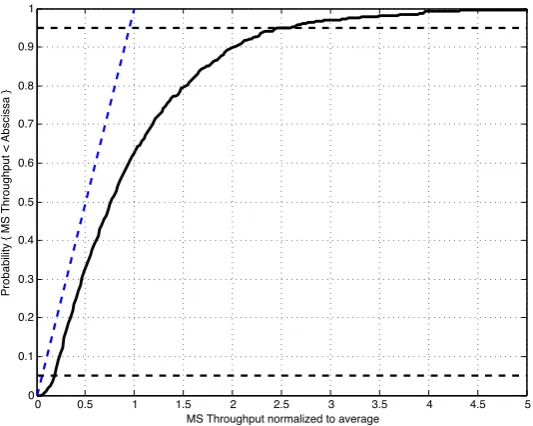
3.8 Exemplary CDF of the user throughput assigned to MBSs . . . 69
3.9 Example CDF of the UG assigned to MBSs . . . 70
3.10 Example CDF of the SINR assigned to MBSs . . . 71
3.11 Example CDF for the normalized MS throughput representing fairness of the network . . . 72
3.12 Example CDF for the MS / RN throughput separated in different user groups 73 3.13 Virtual Positioning of RNs . . . 74
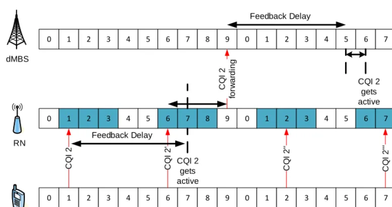
3.14 CQI Feedback for wireless backhaul . . . 76
3.15 Additional Delay caused by CQI Feedback Forwarding for the RN Access Link . . . 77
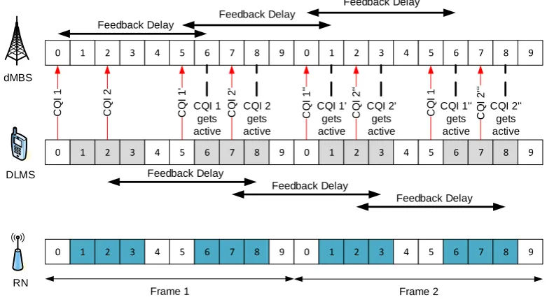
3.16 Additional CQI Feedback for DL MSs . . . 78
3.17 No adaptation of HARQ feedback delay necessary . . . 79
3.18 Principle two-hop MS specific buffer status . . . 80
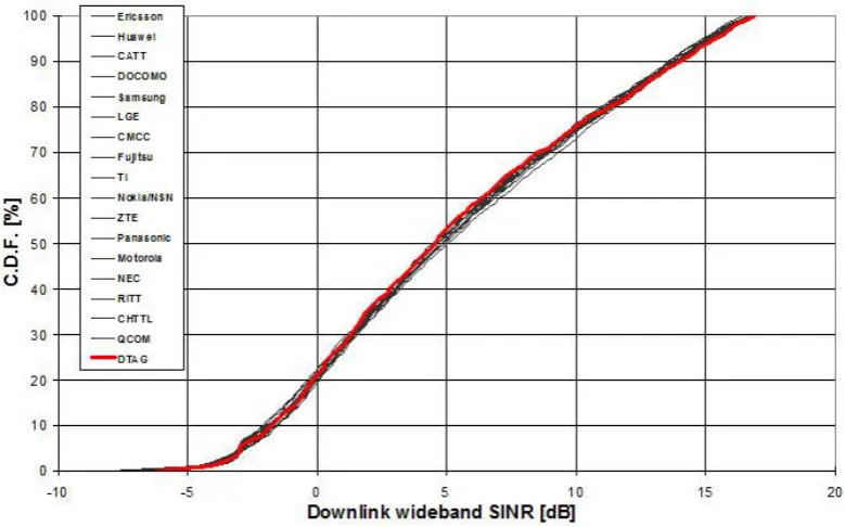
3.19 3GPP calibration results for the User Geometry . . . 82
3.20 3GPP calibration results for the DL normalized user throughput . . . 83
3.21 3GPP calibration results for the average SINR per UE . . . 83
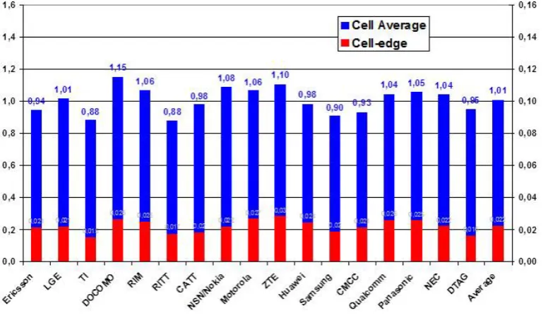
3.22 3GPP calibration results for the cell average and the cell edge Spectral Efficiency (SE) . . . 84
4.1 Possible serving and interfering links during backhaul transmission time . 88 4.2 Possible serving and interfering links during RN access transmission time 89 4.3 Simple network scenario for example optimization approach . . . 93
4.5 Numerical example for simplified optimization approach . . . 96
4.6 Basic idea of a meta heuristic to find a near optimal solution . . . 97
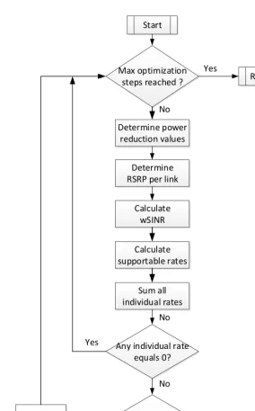
4.7 Flow Chart of the applied genetic algorithm . . . 99
4.8 Fitness proportionate selection to create couples of parents . . . 104
4.9 One point crossover mechanism to create offspring . . . 105
4.10 Sensitivity analysis with different mutation rates . . . 106
4.11 Maximum fitness values with different mutation rates . . . 106
4.12 Example of GA optimization process with Equation 4.19 . . . 107
4.13 Numerical example of an optimized transmission power pattern . . . 108
4.14 Example of possible optimized transmission power configuration over time 108 4.15 Example of possible optimized transmission power subband configuration over frequency in the ALSF . . . 109
4.16 Flow chart of the adapted two hop proportional fair scheduler . . . 110
4.17 Flow chart for the resource allocation considering co-scheduling, two-hop proportional fairness and frequency selectivity . . . 113
4.18 Two hop co-scheduling among directly attached UEs and RNs with cor-rect frequency selective decisions . . . 115
4.19 Illustration of the compared synchronous scheduling strategies after sub-band power optimization . . . 116
4.20 Simple network scenario for numerical examples of the two-hop propor-tional fair metric . . . 118
4.21 Example with equal supportable rates among MSs . . . 119
4.22 Example with higher supportable rate for MS1 and equal supportable rates of MS2 and two-hop MS3 . . . 120
4.23 Example with higher supportable rate for two-hop MS3 and equal sup-portable rates of MS1 and 2 . . . 121
4.24 Example with highest supportable rate for two-hop MS3 and equal lowest supportable rates of MS1 and 2 . . . 122
4.25 Required signalling for the proposed hybrid RRM scheme . . . 124
5.4 Throughput and fairness of all MSs and RN BH for the different cell se-lection metrics . . . 132 5.5 Throughput and fairness of all MSs and RN BH for with and without
co-scheduling functionality . . . 133 5.6 Throughput of all MSs and RN BH with different RN AL CQI feedbacks 135 5.7 Throughput of MBS and RN MSs with different RN AL CQI feedbacks . 135 5.8 Throughput of all MSs and RN BH with fitness function o1 and
schedul-ing policy 1,2 and 3 . . . 136 5.9 Throughput of all MBS and RN MSs with fitness function o2 and
schedul-ing policy 1,2 and 3 . . . 136 5.10 Throughput of all MSs and RN BH with fitness function o2 and
schedul-ing policy 1,2 and 3 . . . 137 5.11 Throughput of all MBS and RN MSs with fitness function o2 and
schedul-ing policy 1,2 and 3 . . . 138 5.12 Final Comparison of the UE and RN throughput for reduced feedback
based on max value and fitness function o2 with scheduling policy 2 . . . 139 5.13 Comparison of the RN BH SINR values for reduced feedback based on
max value and fitness function o2 with scheduling policy 2 . . . 140 5.14 Comparison of the MBS and RN UE SINR values for reduced feedback
based on max value and fitness function o2 with scheduling policy 2 . . . 140 5.15 Comparison of the MBS and RN UE SINR values for reduced feedback
based on max value and fitness function o2 with scheduling policy 2 . . . 141 5.16 Final Comparison of the Fairness Criterion . . . 142 5.17 Final Comparison of potential MBS and RN transmission power savings
on the DL data channel . . . 142
Acknowledgements
Abstract
Acronyms
3GPP Third Generation Partnership Project
AC Admission Control
ACK Acknowledgement
AF Amplify and Forward
AL Access Link
ALSF Access Link Subframe
AoA Angle of Arrival
ASA Angle of Arrival’s Spread
ASD Angle of Departure’s Spread
AWGN additive white Gaussian noise
BHSF Backhaul Subframe
BL Backhaul Link
BLER Block Error Rate
BS Base Station
C-RAN centralized radio access network
CAPEX Capital Expenditure
CDF Cumulative Distribution Function
CQI Channel Quality Information
CR Composite Rate
CRE Cell Range Expansion
CSI Channel State Information
CU Centralized Unit
deNB donor eNB
DL Downlink
dMBS donor MBS
DS Delay Spread
DT SLS Deutsche Telekom System Level Simulator
DU Decentralized Unit
eNB eNodeB
EPC Evolved Paket Core
FD Full Duplex
FDD Frequency Division Duplex
FFR Fractional Frequency Reuse
FFT Fast Fourier Transformation
FIFO First Input First Output
FSS Frequency Selective Scheduling
GA Genetic Algorithm
gNB gNodeB
HARQ Hybrid Automatic Repeat Request
HetNet Heterogeneous Network
HSS Home Subscriber Server
IAB Integrated Access and Backhaul
ICIC Inter Cell Interference Coordination
IP internet protocol
IR Impulse Response
ISD Inter Site Distance
K K-factor
KPI Key Performance Indicator
LA Link Adaptation
LLS Link Level Simulation
LoS Line of Sight
LSP Large Scale Parameter
LTE Long Term Evolution
LTE-A Long Term Evolution Advanced
MBS Macro Base Station
MBSFN Multicast Broadcast Single Frequency Network
MCS Modulation and Coding Scheme
MIESM Mutual Information Effective SINR Mapping
MIMO Multiple Input Multiple Output
MME Mobility Management Entity
MS Mobile Station
NG Next Generation
nLoS non Line of Sight
NP non-deterministic polynomial
OFDM Orthogonal Frequency Division Multiplexing
OFDMA Orthogonal Frequency Division Multiple Access
OPEX Operational Expenditures
P-GW Packet Data Network Gateway
PA Power Amplifier
PAV Power Adaptation Value
PBCH Physical Broadcast Channel
PDCCH Physical Downlink Control Channel
PF Proportional Fair
PL Path Loss
PMI Precoding Matrix Indicator
PRB Physical Resource Block
PSO Partical Swarm Optimization
QoS Quality of Service
QPSK Quadrature Phase Shift Keying
RAN Radio Access Network
RI Rank Indicator
RN Relay Node
RR Round Robin
RSRP Reference Signal Received Power
S-GW Serving Gateway
SA Simulated Annealing
SDMA Space Division Multiple Access
SE Spectral Efficiency
SF Shadow Fading
SFR Soft Frequency Reuse
SINR Signal to Interference plus Noise Ratio
SISO Single Input Single Output
SLS System Level Simulation
SNR Signal to Noise Ratio
SSP Small Scale Parameter
TBS Transport Block Size
TCP Transmission Control Protocol
TDD Time Division Duplex
TDM Time Division Multiplexing
TS Tabu Search
TTI Time Transmission Interval
UE User Equipment
UG User Geometry
Chapter 1
Introduction
1.1
Motivation and Overview
systems is that typically an optimal solution requires a prohibitively exhaustive solution search. Furthermore, practical limitations have to be carefully taken into account. Various RRM strategies related to the aforementioned targets for all kind of RN types have been intensively studied in the past years.
However, the existing results in the literature are diverging in terms of the correct modelling of the underlying network topology and the system assumptions. Often ideal assumptions of the radio channel knowledge, the feedback delay and the wireless back-haul conditions are assumed. A lot of proposed methods will only work under such ide-alized conditions and will suffer in real large scale networks. These aspects are the main motivation for the work presented in this Thesis.
1.1.1
Objectives statement
The Thesis therefore contributes an answer to the question if it is possible to improve the overall user throughput of the system by designing a hybrid radio resource management approach under practical limitations for relay-extended networks. To achieve this target a very detailed modelled system level simulation is applied. More specifically the research problem is decomposed in three parts for the hybrid RRM scheme as follows:
• A decentralized improved cell selection scheme.
• A cell-centralized improved short-term radio resource scheduler.
• A network centralized long-term transmission power adaptation algorithm, which improves the quality of the non-ideal wireless relay backhaul link.
1.2
Contribution of the Thesis
The contribution of the Thesis is related to radio resource management (RRM) and Inter Cell Interference Coordination (ICIC) in relay enhanced Orthogonal Frequency Division Multiple Access (OFDMA) heterogeneous networks for the downlink transmission. It aims to improve the non-ideal wireless backhaul connection of relay nodes to the serv-ing donor macro base stations without throughput losses for the users directly connected to the macro base stations. This is a challenging task as the macro users and the relays have to share the available radio resources. The theoretical multi objective optimization problem cannot be solved optimally in practical systems. To this end, the problem is de-composed in three sub-problems to reach an improved system performance. The major contributions of the Thesis are described as follows:
1. The first contribution is a comprehensive system level simulation analysis on dif-ferent cell selection schemes to improve the overall user throughput of a relay enhanced large scale OFDMA heterogeneous network under practical constraints. Here, buffer en-abled half duplex non-transparent decode relay nodes with non-ideal wireless backhauls are considered. An adapted cell selection scheme as well as a macro cell-centralized im-proved two-hop proportional fair scheduling scheme is proposed.
1.3
Thesis structure and content
The Thesis is organized as follows: In Chapter 2 an introduction to the Radio Access Network (RAN) architecture is presented, which has been agreed recently in 3GPP. Then different kind of relay nodes are introduced and possible operating modes are described in detail. A comprehensive summary on the existing literature of solutions for enhanced radio resource management for relay-extended networks is provided. Based on that, rel-evant existing radio resource management solutions are considered. Finally the research problem is described and the requirements are derived for the novel low complexity hy-brid radio resource management scheme proposed in this Thesis.
Chapter 3 explains at first, why a system level simulation is the necessary tool to in-vestigate the defined research problem. It includes the detailed description of the method-ology to be used, implying the description of used models, followed by the defined Key Performance Indicator (KPI)s to analyse the results. Then, the System Level Simulation (SLS) is calibrated to verify it as a comparable tool within the 3GPP simulation frame-work. Afterwords, the extensions done throughout this Thesis are described and analyzed to introduce layer 3 in-band Frequency Division Duplex (FDD) half-duplex RNs.
Input
Parameter Initialisation j
Scenario Initialisation
Sub-Problem 1:
Cell Selection
Sub-Problem 3: Adaptation of TxPower
pattern
Sub-Problem 2:
Adapted radio resource scheduling
Snapshot Loop
M N
Scenario loop
Channel
update End
Analysis update SINR
calculation Pre Processing
i
Figure 1.1: Principle flow chart of the SLS with respect to the hybrid RRM scheme and its decomposed sub-problems
Chapter 5 contains a performance analysis of different cell selection schemes and cell-centralized functionalities, followed by the presentation of the final assumptions and results of the carried out SLS analysis for the proposed hybrid radio resource management (RRM) scheme.
Chapter 2
Relay extended OFDMA Networks
In this Chapter an introduction to the RAN architecture is presented which has been agreed recently in 3GPP. Then different kind of relay nodes are introduced and possible operating modes are described in detail. Based on that, relevant existing radio resource management solutions are considered. Finally the research problem is described and the requirements are derived for the novel low complexity hybrid radio resource management scheme proposed in this Thesis.
2.1
Network architecture in 3GPP
2.1.1
Core network
The 3GPP defines the global mobile radio telecommunication standard including the core and access network as well as service capabilities of the system. The Long Term Evo-lution (LTE) specific core network was first introduced in Release 8 of the specification and defined as Evolved Paket Core (EPC) in [6, 7]. The agreed design principle was to have a flat hierarchical architecture, which means to define only a few network nodes to handle the data traffic performance in a more cost efficient manner, compared to previous 3G communication standards, defined in [8]. As a second principle requirement, the EPC architecture depicted in Figure 2.1 handles the payload (user data) and signalling traffic (further referred as control plane) in a separated way to make the scaling of both data types independent to each other. Due to the introduced functional split, dimensioning and adapting the network can be done in a more flexible way and is easier to adapt specific operators’ needs.
inter-faces between each other. The Home Subscriber Server (HSS) basically is a database containing user and subscriber specific information, such as authentication and access au-thorization information, besides others. The Serving Gateway (S-GW) and Packet Data Network Gateway (P-GW) handle the users’ data traffic further referred as user plane. Those network elements mainly transport the IP data traffic between the mobile stations and the external networks behind the mobile core. The S-GW interconnects the user plane between the core network and the Radio Access Network (RAN), defined as multiple eN-odeB (eNB)s via the S1-u interface, while the P-GW interconnects the EPC with external internet protocol (IP) networks via the SGi interface. The P-GW also supports function-alities such as IP address allocation or policy control and charging. The Mobility Man-agement Entity (MME) is responsible for handling the signalling traffic, further referred to as the control plane. The MME is interconnected to the RAN via the S1-c interface. Mainly, it is defined to support mobility and security for the radio access. Moreover, the MME handles MS tracking and paging when subscribers are connected in idle-mode.
MME HSS
S-GW P-GW
Internet, Operator services
eNodeB
RAN
[image:27.652.191.347.370.632.2]S11
Figure 2.1: EPC Core Architecture [6, 7]
2.1.2
Radio access network
that, the radio sites are interconnected via the defined X2 interface to exchange different types of control messages for e.g. possible Base Station (BS) interference cooperation and load balancing schemes as well as the handover related information. Further detailed information can be found in [10]. Since this Thesis focuses on relay node RN extended RAN, an RN is depicted as well in Figure 2.2. Relay nodes are introduced to the 3GPP architecture in Release 10 of the specification. The details on the definition of different RN types introduced by 3GPP can be found in [11] and will be discussed in the upcoming Section 2.2 as well. As can be already seen in Figure 2.2, an RN is a node type which is interconnected to the network via a wireless backhaul connection to an eNB, further referred as donor eNB (deNB).
MME S-GW
Core Network
deNB
RN UE
eNB UE
Figure 2.2: LTE-Advanced RAN Architecture with RN [9]
network, which means that LTE is a part of the 5G system. Second, due to the newly in-troduced CU in the NG RAN higher flexibility in data forwarding to transmission points as well as better possibilities to coordinate resource allocation among DUs are introduced.
Figure 2.3: NG RAN Architecture [12]
Figure 2.4: NG RAN gNB Architecture [13]
2.1.3
New study item for 3GPP Release 15/16 revisiting relay nodes
outcome of the research presented in this Thesis could contribute to the defined study item, providing deeper understanding of the RRM aspects in the RN-extended networks and revealing detailed insights on possible affordable non-prohibitive signalling require-ments on the wireless backhaul. Becauce of that, the hybrid RRM scheme that will be presented in this Thesis has been designed to have low complexity and small signalling overhead. The necessary low amount of additional signalling traffic for the proposed hybrid scheme is described in detail in Section 4.5.
2.2
Relay types in 3GPP
In this section the focus lies on the outcome of 3GPPs work done for the specification of RNs in LTE-A Release 10. As already mentioned, small cells in general are consid-ered as one means to increase capacity and coverage. Besides the possibility to densify the conventional homogeneous Macro Base Station (MBS) network, the introduction of small cells aims to reuse the spectrum most efficiently. To further densify the macro cell network, has critical drawbacks for an operator due to high OPEX and CAPEX as well as practical implications due to very few possible additional accessible site locations [2]. There are different types of small cells introduced to the mobile network. Small cells -pico cells, femto cells and Relay Nodes (RN) - are node types which typically transmit with lower amount of power compared to an MBS [1, 14, 15]. The main target to use such types of nodes is to overcome large path losses which imply low spectrum efficiency usage. Thus, decreasing the path loss by shifting the serving node nearer to terminals enables reusing the system bandwidth with high efficiency gains.
Mobile Core
Internet
Macro Pico
Relay Femto
Figure 2.5: A heterogeneous network consists of wireline backhauled macro, pico, femto, cells and wireless backhauled RN
To enable a communication between the dMBS and the corresponding RNs, Figure 2.6 shows the interfaces defined by the 3GPP to connect an RN as well as an User Equipment (UE), further referred to as a Mobile Station (MS). The Uu interface connects the MS to the RN via the Access Link (AL), while the Un interface is dedicated to the Backhaul Link (Backhaul Link (BL)) interconnecting the RN with the dMBS.
EPC S1 Un Uu
eNB RN UE
Figure 2.6: Defined interfaces for RN extended mobile networks by the 3GPP
For further clarification, different RN types exist, with different supported function-alities and operating modes. The 3GPP has defined three RN types for LTE-A, mainly distinguished based on the transmitted sublayers of the radio protocol stack and thus the supported signal processing of the considered RN type including different functionality.
means to extend the coverage at low cost, while accepting spectral efficiency losses due to no additional signal processing.
PHY MAC
RLC PDCP
eNB Layer 1 repeater MS
PHY MAC
RLC PDCP
RRC
analog PA
RRC
Figure 2.7: Layer 1 RN Protocol Stack
PHY MAC
RLC PDCP
eNB Layer 2 RN MS
PHY MAC
RLC PDCP
RRC
PHY MAC
RRC
Figure 2.8: Layer 2 RN Protocol Stack
A Layer 3 RN, also known as self backhauling RN, can be considered as a separate base station (BS). In addition to the independent Admission Control (AC) and the mobil-ity management functionalmobil-ity, it also performs decentralized radio resource scheduling, including re-encoding and modulation, HARQ, as well as choosing the MS specific trans-mission mode, such as beamforming or spatial multiplexing, and other radio functions, such as ciphering, MS data concatenation/segmentation, etc. It performs the complete signal processing as a separate BS. The radio protocol stack is depicted in Figure 2.9 and is in focus of the work presented in this Thesis. For additional detailed information about the functionalities of the RAN protocol stack the reader is referred to [9, 12, 17].
PHY MAC
RLC PDCP
eNB Layer 3 RN MS
PHY MAC
RLC PDCP
RRC
PHY MAC
RLC PDCP
RRC RRC
The summary of the main advantages and disadvantages of the introduced RN types is given in Table 2.1.
Table 2.1: Summary of further RN type attributes
RN node type Advantages Disadvantages
Layer 1 RN - Low additional processing delay - Lower cost due to simple func-tionality
- Low impact on standardization
- Noise and interference ampli-fied with desired signal
- Decreased spectral efficiency Layer 2 RN - No noise and interference
ampli-fication due to the decoding func-tionality
- Error rate improvement due to HARQ support
- Support of resource and network cooperation
- Processing delay
- dMBS to RN consumes radio resources
- Major standardization impact (L2 radio protocols needed) - High additional amount of signalling
Layer 3 RN - No noise and interference ampli-fication due to decoding
- Small standardization impact (reuse of existing MBS protocols) - Error rate improvement due to HARQ support
- Support of resource and network cooperation
- Highest processing delay - dMBS to RN consumes radio resources
Besides the existing RN types defined by the 3GPP, there is a need to further differ-entiate between RNs regarding the mode of operation. In the following an introduction to the most relevant functionalities is given. Further details on possible RRM schemes and their practical implications, such as additional necessary signalling overhead and the assumed level of centralization can be found in Section 2.3.
1. The wireless backhaul link operates either in-band or out-of-band: The wireless backhaul link operates in the same frequency band as the access link or in a sepa-rated band.
2. Half or full duplex mode: While in the Half Duplex (HD) mode the RN is not able to transmit and receive at the same time, radio resources need to be allocated with a Time Division Multiplexing (TDM) based scheme. In the Full Duplex (FD) mode advanced interference cancellation techniques or sufficient receive and trans-mit isolation have to be considered, due to the creation of self interference at the RN
is part of the dMBS. Therefore the 3GPP differentiates between type 1 RNs as non-transparent and type 2 RNs as non-transparent RNs. Based on that, further clarification is needed with respect to the level of centralization of the designed RRM scheme.
4. Network-centralized, macro cell-centralized or RN specific decentralized RRM ap-proaches: One of the most critical challenges and often overseen is the assumed available Channel State Information (CSI) feedback. A lot of the proposed RRM schemes rely on impractical amount of CSI [18] which will be further discussed in Section 2.3. For instance, sophisticated network-centralized Coordinated Multi Point (CoMP) schemes, which typically require quantized explicit feedback with tight delay requirements [19, 20], seem to be impractical in combination with RNs due to additional necessary feedback of the RN access link, which needs to be for-warded to the dMBS in a first step and then gathered at a central controller. On the one hand scare radio resources need to be used carefully and cannot be allocated with an exceeding amount of overhead, while on the other hand additional delays due to the introduced two-hop connections need to be taken into account regarding coherent channel states over time. Especially, this is already an critical issue in conventional networks for FDD downlink transmissions.
Furthermore, in the existing literature it is often not obvious, which type of RN is consid-ered. Moreover, It is often unclear which additional functionalities are supported at the RN based on the proposed methods. Furthermore, necessary considerations of the feed-back delays and the caused feedfeed-back overhead by the algorithm is often left open. The existing solutions are further discussed in Section 2.3.
2.2.1
Enabling Time Division Multiplexing (TDM) for half duplex
RNs in 3GPP
which control and user data is transmitted.
MBS RN MS
MBS RN MS
MBSFN subframe
Normal subframe BL
AL
AL
Figure 2.10: Downlink half duplex RN radio link operation
Further details of the applied TDM scheme in LTE Release 10 are illustrated in Fig-ure 2.11. The MBSFN subframe gives the opportunity to transmit at first the Physical Downlink Control Channel (PDCCH), presented as the brown control data region. This information is expected by each MS within every subframe. After the system relevant control channel transmission the RN switches to reception mode within one Orthogonal Frequency Division Multiplexing (OFDM) symbol, shown as the grey area on the left. The RN is now able to receive control (shown as the dark green area) as well as user data from the dMBS (light green data region). During that time the MSs attached to the RNs are not served with data. At the end of an MBSFN subframe the RN again switches back to sending mode within one OFDM symbol, illustrated as the grey area on the right.
Moreover, there exist some additional constraints which are summarized as follows. In the LTE FDD downlink frame structure several subframes are not configurable as MBSFN subframes since they transport system relevant information such as the Physical Broadcast Channel (PBCH) (1st subframe) or the Primary and Secondary Synchronisa-tion Signal (P/S-SS) (5th, 6th and 10th subframe). In addiSynchronisa-tion, the MBSFN subframe has a periodicity of 8 milliseconds (ms) while the LTE frame structure is defined with a periodicity of 10ms. In principle, each RN could be configured in the sending or the re-ceiving modes at different times. However, this might introduce critical unwanted RN to RN interference. The used number of MBSFN subframes can be updated every 40ms via the PBCH to react on, e.g. a changing traffic demand of the RN (see also [3]). This results in a higher dynamic of interference than in a system without RN extension and introduces additional challenges to cope with, such as the aforementioned faster outdated channel feedback information in FDD downlink [22]. The limitations and additional overhead as-sumptions are carefully taken into account in this Thesis and further described in Section 3.5.
2.2.2
Full duplex and Half duplex relay operation mode
Half Duplex
Full Duplex
RN
MS
dMBS
RN
MS
dMBS
RN
MS
dMBS
Figure 2.12: Full Duplex vs. Half Duplex transmission
2.2.3
Radio channel feedback
trans-mission at the MBS, but also channel information about the backhaul link (BL) as well as for the second hop is required. Therefore, additional signalling feedback needs to be provided from RN to its dMBS to derive which radio resources the RN gets allocated in an appropriate manner. Further details on the proposed two-hop frequency selective scheduling approach in this Thesis and the implication on necessary feedback can be found in Section 4.4 and 4.5. The considered scheme aims to minimize the necessary ad-ditional feedback. On the one hand there is a need to reduce the necessary measurements at the MSs and on the other hand it is necessary not to overload the wireless backhaul of the considered non-transparent type 1 RNs with signalling traffic. Some further insights on possible feedback types and the implication on the additional amount of overhead in-troduced by those are discussed in the following.
There are two different feedback types possible. The first type, often referred as the Channel Quality Information (CQI) feedback, and further referred as implicit feedback, typically sends back indications of the channel conditions, e.g. as indicators of the recom-mended MCSs to use in multiple subbands. Such type of feedback is introduced to LTE in Release 8 and further enhanced until the latest Release 15 in [27]. The second type is known as explicit CSI feedback. While the CQI feedback is a means to find a trade-off between the information accuracy and the resource efficiency, the quantized explicit CSI feedback introduces higher signalling overhead. The quantized impulse responses provide greater detailed information about the radio links. To support advanced coordi-nated multipoint CoMP schemes or precoder designs, explicit information is required for instance to support downlink joint transmission in FDD systems [28].
feedback from RN to dMBS is carefully limited. The additional feedback delay is con-sidered as well and described in Section 3.5.4.
2.2.4
Fixed relay deployment scenarios and commercial aspects
Potential deployment scenarios of fixed half duplex RNs have been widely discussed [1]. While scenarios to extend or expand the coverage of the RAN are quite obvious, poten-tially useful scenarios to increase the capacity are less known. Due to the limitation of the wireless backhaul link the loss in the transmission time and the introduction of ad-ditional interference, especially when half duplex inband RNs are considered, it is quite challenging to increase the RAN capacity. However, in a scenario where an MS hotspot is detected and a relatively high amount of users are in the vicinity of an RN it might be possible to improve the capacity, as well [29]. Figure 2.13 shows three RNs deployed in different scenarios. While the upper relay provides coverage extension and the lower RN fills a coverage hole (e.g. shadowed areas by buildings or a poor indoor coverage), an RN might be deployed at an MS hotspot to improve the capacity of the network. In an MS hotspot area, many users at once might profit from a high channel quality of the access and backhaul links. Based on that the possible two-hop connection could outperform the direct links to the MBS.
MBS MS
RN
Typically RN deployments bring certain practical advantages compared to the wireline deployed small cells. The operator has to cope with a limited amount of locations where wired backhaul connection can be provided. In addition, the wireline connection in the case of pico cells generates rather high costs in terms of OPEX and CAPEX [16, 30, 31]. When considering femto cells an unwanted unplanned interference situations might appear in the network due to the loss of the control of the appearance of femto cells, which might influence the user experience in an unforeseen chaotic manner. Therefore, the relay nodes can be seen as an alternative useful means in scenarios where fixed line backhauled small cells are difficult to deploy [32]. Furthermore, additional potential cost savings are identified, when the considered RN type and the potentially applied RRM scheme does not necessarily need a Line of Sight (LoS) conditioned ideal wireless backhaul. This reduces planning effort and moreover, potential cost savings appear if no additionally deployed directed receive antenna would be deployed at the RN, which might not make sense anyway in a urban or sub-urban environment to improve the backhaul link [33]. However, all these potential cost savers makes it even more challenging to increase the capacity by means of introducing RNs.
Throughout this Thesis worst case assumptions for the wireless inband backhaul are considered, which makes the solution attractive to save costs. The backhaul link does not necessarily have LoS conditions which reduces planning effort and increases the amount of available potential sites. No additional antenna gains are assumed in the sending and the receiving direction, which makes it unnecessary to equip the RNs with additional antennas. The considered scenario consists of RNs deployed in the vicinity of randomly placed user hot spots within the umbrella macro base stations. Comparable reference results are gathered and comprehensively described in [29].
2.3
Radio resource management in RN extended
hetero-geneous mobile networks
discussed, an introduction how to calculate the capacity in a mobile network is given, followed by the general problem formulation. Based on the defined theoretical problem statement the solution of this Thesis decomposes the problem in three sub-problems with different centralization levels later on in Chapter 4, as the work of this Thesis aims to improve the overall network capacity by the design of an hybrid RRM scheme.
2.3.1
Capacity of mobile networks
As previously discussed in Section 2.2.4 RNs should either be deployed to improve the coverage or the capacity. Coverage can be achieved by providing the smallest required received power of the desired signal (in uplink at the BS and in downlink at the MS). In principle, coverage can already be provided with a rather low amount of BS located at high altitude on a low carrier frequency, as e.g. often deployed in rural areas.
The network capacity refers to the maximum amount of data the system is able to transmit on the air interface in a fraction of time (Mbps). To estimate the overall reachable capacity of a large scale system (e.g. by means of simulations used in this work), a full load situation needs to be considered, where all BSs transmit on all resources as much data as possible [34, 35]. Further information about the used simulator in this Thesis can be found in Chapter 3. The possible supported rate Rof a single wireless link n can be estimated based on the Shannon-Hartley theorem, as defined in Equation 2.1, where B
is defined as the system bandwidth and S/N as the Signal to Noise Ratio (SNR) of the considered wireless link. High SNR enables the possibility to transmit with higher MCS to improve the capacity.
Rn=B·log2
1+ S
N
(2.1)
under the assumption that the appearing interference is Gaussian distributed. In Equation 2.2, the total capacity of a single base stationCBSis defined as the sum of the rates of the existingnwireless links.
CBS=
N
∑
n=1
Rn (2.2)
Equation 2.3 represents the total capacity of the networkCNet in which the capacities of the considered BSs are summed up.
CNet = I
∑
i=1
CBSi (2.3)
Basically, four options are available to increase the network capacity. The first, the easiest but probably the most expensive option is to linearly increase the system band-widthBby using larger amount of spectrum. The second option would be to increase the number of sending and transmitting antennas to send multiple data streams using Space Division Multiple Access (SDMA) [36], based on using Multiple Input Multiple Output (MIMO) channels. As already discussed in Section 2.2, the third option to increase the ca-pacity is to deploy additional BSs and therefore to reduce the path loss between the sender and the receiver (further referred as network densification). This results in an improved quality of the serving signalS, when shifting the sender nearer to the receiving node and thus improving path loss gains. The major drawback of this option, is the additional in-terference, which is introduced to neighbouring cells limiting the possible capacity gain. Therefore, the forth option are possible interference mitigation techniques to again in-crease the network capacity by reducing the interference. The work of this Thesis focuses on the network densification and the interference mitigation option.
2.3.1.1 Capacity in half duplex non-transparent relay extended networks
dMBS
RN
MS
BL
2HAL
MS
AL
Figure 2.14: Link types for an RN-extended Network
Throughout the Thesis, the direct access link (AL) is denoted as the wireless link which serves the directly attached MSs at the MBSs. The wireless backhaul link of the RNs is defined as backhaul link (BH), while the serving link between RNs and MSs attached at the RNs is noted as two-hop access link 2HALs. For further clarification Figure 2.14 shows the existing links in an RN-extended network.
Equation 2.4 gives the expression for the capacity for a single macro BS in an RN-extended network when the RNs are in receiving mode. The capacity is the sum of the rates of the ALsMand BLsJ.
CBS=
M
∑
m=1
Rm+
J
∑
j=1
Rj (2.4)
Equation 2.5 defines the possible capacity of a single RN limited by the rate of the wireless BL jof the considered RN, when the RN is in sending mode.
CRN =
M
∑
m=1
Rm, (2.5)
withCRN ≤Rj
Finally, Equation 2.6 represents the total capacity of the RN extended network with J
as the rates only forward the data to the RNs.
CNet =
I
∑
i=1 CBSi−
J
∑
j=1 Rj+
J
∑
j=1
CRNj, (2.6)
withCRNj ≤Rj
A large network capacity is most relevant for the downlink transmission as this is the dominant amount of traffic in large scale communication systems [37, 38]. Based on that, this work focuses on the downlink. In the following Section 2.3.2 the research problem is defined under several constraints for the considered system in more detail.
2.3.2
Problem formulation
The theoretical optimization problem formulation to maximize the overall system capac-ity is defined as Equation 2.7- 2.12. The considered sum-rate maximization depends on the aforementioned possible rates of the different link types in the Equations 2.4 -2.6 [22, 39, 40].
max(CNetwork) =max k,p,t
M
∑
m=1 J∑
j=1 N∑
n=1Rm,j,n (2.7)
subject to
∑
n∈Nk∑
∈Ktn,k,l·pn,k,l≤Pmaxm,j, (2.8)
j=
0, l=1
j∈ {1,2, . . . ,J}, l=2
(2.9)
m={m∈ {1,2, ...,M}} l=1|2 (2.10)
∑
n∈N
tn,k,l≤1, n∈N (2.11)
Rn=R(tn0,,ki,l,p0,n,ik,l,β) (2.12)
The rate of a single link is derived from the allocated radio subchannel which con-sists of multiple radio resources. Typically, a single radio resource concon-sists of an OFDM frequency subcarrier k transmitted with a power p in a time fraction t, e.g. for the nth
allocated for transmission, as defined in Equation 2.8. A specific subchannel consists of a number of allocated subcarrierskto the considered radio link/channel. Dependent on the supportable MCS, which is dependent on the corresponding effective SINR on the allo-cated subcarriers and the total number of the alloallo-cated subcarriers the throughput of either a AL, BH or a 2hAL can be determined. It is obvious that, the better the effective SINR a higher MCS can be used and thus, an increased spectral efficiency can be expected on the allocated subcarriers. Finally, this results in a higher capacity of the total system. It needs to be further distinguished between time slots l for receiving (1) and sending (2) mode for a relay node j, while the possible served MBS MS can receive data during both time slots. The MS receives data exclusively on the allocated resources from the cell where it is attached. Further, the serving link is denoted as 0 and interfering linksi, respectively in Equation 2.12. The possible RN transmission rate is limited by the half duplex mode of the considered RN type. This means the MS attached to the RN cannot receive more data, than buffered at the serving RN, denoted as buffered dataβ, considered in Equation 2.12
as well. In summary that means, the data rate of an MSnis dependent on the allocated time, power, subcarriers as well as the existing interference in a multi cell environment.
While the sum-rate maximization will result in a maximized capacity but does not consider a fair resource distribution among the individual MSs, fairness constraints need to be taken into account in addition, which is explained in more detail in Section 2.3.7. As is can be seen from Equation 2.12 the maximization of the system capacity will be a multi objective optimization problem, which is typically unsolvable and declared as a non-deterministic polynomial (NP)-hard problem. Such optimization problems are often divided in sub-problems to find at least a solution which still improves the system capacity rather then finding the theoretical optimal solution.
Already in conventional networks, it is a challenge to optimally allocate the available resources, due to the dynamic channel variations, the channel estimation errors, the lim-ited total transmit power, processing time and the channel feedback. Not every subcarrier can be dynamically modulated and encoded in every OFDM symbol [41–45]. Due to complexity reasons a grouping of the available resources is necessary [46].
DL symb
N OFDM symbols One downlink slot Tslot
0
l lNsymbDL 1
RB sc
DL RB
N
N
subcarriers
RB sc
N
subc
arriers
RB sc DL symb N
N
Resource block
resource elements
Resource element(k,l)
0
k
1
RB sc DL RB
N N
k
Figure 2.15: Downlink resource grid in LTE [47]
Further, if multiple PRBs are scheduled to a specific MS, the Transport Block Size (TBS) (bits per TTI per MS) needs to be modulated and encoded with a single MCS. Due to that, a link adaptation (LA) algorithm needs to derive the used MCS for transmission [48–52]. Moreover a limiting factor for optimal resource allocation of the PRBs is the accuracy and granulation of the assumed channel feedback. For instance, if in an LTE network frequency selective scheduling is applied, it would be of great advantage to have knowledge of the channel states of each PRB in each TTI to perform an ideal LA to get the best performance. However, this would increase the measurement requirements of the MSs and increases the signalling overhead a lot. To this end, it is finally necessary to find a good practical trade-off between, the signalling overhead, the maximum system capacity and fairness among the MSs [53, 54]. Detailed information on the system model used in this work, which assumes such a trade off, can be found in Section 3.
to find a practical solution to improve the system capacity. In the upcoming section an overview on existing designed RRM schemes for relay extended networks is summarized, which try to improve the system capacity. Different important works from the industry and academia are identified and evaluated in the context of the necessary feedback over-head, the additional complexity and the assumed level of centralization.
2.3.3
Level of centralization and signalling overhead for RRM schemes
To fairly compare proposed RRM algorithms two aspects are mainly relevant here: 1. It is necessary to consider the introduced channel feedback overhead as input
in-formation for the RRM scheme and thus the type of feedback (implicit feedback or explicit feedback, as described in Section 2.2.3).
2. It is important to distinguish among the levels of the centralization and wether the required feedback information arrives with a delay. Typically, three levels of cen-tralization are considered:
• A network-centralized RRM scheme, where it is required to gather global knowledge about channel states to handle the resource allocation for the entire network.
• A cell-centralized scheme considers the resource allocation of the dMBS and of the RNs located in its coverage area.
• A completely decentralized scheme does the resource allocation only based on local channel information of available information between the serving cell and the MSs.
RN
MS
RNdMBS
CU
MSMBS
AL feedback AL / BH feedback
Collected feedback
AL feedback
Decentralized Cell-centralized
Network-centralized
Figure 2.16: Level of RRM centralization and corresponding feedback requirement for FDD downlink
RN
MS
RNdMBS
CU
MSMBS
AL feedbackCollected feedback
Decentralized Cell-centralized
Network-centralized
Figure 2.17: Level of RRM centralization and corresponding feedback requirement for TDD
For instance, Li et al. present in [55] a theoretical upper bound calculation with fair-ness constraints for a cooperative transparent relay network with centralized RRM, con-sidering multiple two hop connection to a single receiving node. They conclude, that in practical RN systems, such a centralized approach will introduce prohibitive signalling overhead and recommend to focus on distributed RRM schemes in the future.
In [39] two different cell-centralized RRM schemes for a single MBS aided with a single non-transparent RN environment are considered and compared with a network centralized approach. Perfect knowledge about the explicit CSI is assumed on each sub-carrier and no inter cell interference is considered. A substitute information of the RN to MS links is reported back to the dMBS. The information consists of a channel matrix (number of MSs times the number of subcarriers), gathered and fed back by the RN. It is assumed that for each time slot such information is available at the MBS to perform the resource allocation. Even with the already relaxed feedback information, in a multicell environment with inter cell interference a very short feedback periodicity would be nec-essary, which is impractical due to the very high amount of overhead and the additional measurements, which would still occur.
Moreover, for a single cell environment with a single transparent RN theoretical upper bound capacity calculations are performed, assuming a MIMO channel in [56]. Under the assumption of the perfect explicit channel knowledge, the authors derive an optimal relay precoding matrix to separate the relay MIMO channel into multiple parallel Single Input Single Output (SISO) sub-channels, to result in the maximum capacity of the RN supported MIMO link.
Section 2.3.5). A heuristic algorithm is applied, adapting the assignment in such a way that the system capacity is improved under consideration of the quality imbalance of the two hops. Once the algorithm has found an improved resource assignment, the decision is taken as granted and a power allocation algorithm is performed, which distributes the total available power among multiple two hops, based on a water filling approach.
The authors in [58] propose a cell centralized algorithm to balance the resource al-location between a single dMBS and six RNs placed in its coverage area. They aim to maximize the system throughput under fairness consideration using a game theoretical approach. It is not clearly stated if the authors consider an FDD or TDD system. How-ever, the algorithm needs to be aware of the actual SINR values of MSs and RNs at a central point to allocate the resources. Having in mind the necessary distinction depicted in Figure 2.16 and 2.17 the cell centralized approach would need a lot of forwarded chan-nel information of the MSs served by the RN, even in TDD mode, to gather the necessary amount of SINR values to gain from the scheme.
Also RRM schemes for large scale networks have been considered under the assump-tion of perfect explicit and implicit channel knowledge.
For instance, the authors in [40] consider a joint backhaul and access optimization problem for a network-centralized radio access network (C-RAN) TDD system. They assume to have network wide explicit channel knowledge at the central C-RAN control entity and ideal backhaul conditions. Therefore, the MBSs need to send a very large amount of collected CSI information to the C-RAN central entity. Besides that it is as-sumed in that the MBS only serves RNs, while no MBS-MS connections are considered in the network. The scheme cannot be applied to FDD systems due to the very challenging feedback requirement.
the TDD in downlink transmission, the overhead due to the feedback of CSI from MSs to their central controllers grows linearly with the number of MSs. Therefore, they propose to reduce the overhead, by introducing a feedback threshold broadcasted by the central controller. Only if a certain user has the potential to gain based on exceeding the thresh-old the channel information is updated. The central controller collects new data from the MBSs and RNs which have measured the new CSI. However, in FDD the MSs and RNs would need to report a lot of feedback at first with additional delay to the serving cells, before it could be collected by the controller. Moreover, a rather optimistic assumption is used when assuming an directional receive antenna at the RN with 20dBi antenna gain. LoS conditions are assumed as well for the backhaul connection. These assumptions makes it easy to outperform direct links and can be seen as too optimistic.
In [60], a cell-centralized scheme is proposed to maximize the data rate of an two hop MS by adjusting the time ratio between backhaul and access links to counteract on the different channel states of both as no buffers are assumed at the RNs. The scheme is shown to improve fairness and system throughput. Perfect explicit channel knowledge is assumed and no further information is given on the influence of additional feedback delay of the second hops. They consider only one macro cell and thus they do not take into account the inter MBS interference. The authors assume full flexibility of switching between transmit and receive time slots which is impractical in large scale networks due to the interference uncertainties when neighboring cells have relays which receive and transmit in different time instances. The channel information would be outdated very fast and result in a higher error rate probability.
information about feedback delays could be found and no further information about the assumptions of the wireless backhaul are given. Based on the discussed schemes and the underlying assumptions regarding the feedback and the level of the centralization the main advantages and disadvantages for the different levels of centralization are summarized in Table 2.2.
Table 2.2: Advantages and Disadvantages of the RRM centralization level RRM
Central-ization Level
Advantages Disadvantages
Network central-ized
- Global feedback knowledge enables highest possible gains
- Dependent on the required feedback type, possibly pro-hibitive huge overhead
- Additional backhaul delay for the second hop has to be con-sidered
- Possible outdated feedback in a real environment which makes network centralized schemes less attractable for real networks especially for FDD
Cell centralized - Macro cell wide channel knowledge enables possi-ble gains for RN extended networks
- Additional feedback is re-quired about the second hop at the dMBS.
- Additional delay due to feed-back forwarding from RN to MBS
- The type of feedback needs to be carefully considered. It might be a prohibitive amount of feedback due to the usage of scarce wireless backhaul re-sources
Decentralized - Lowest amount of possible additional overhead
- The cell selection can be done decentralized
- Only local channel knowledge is considered
- Lowest or no gains can be ex-pected due to the loss of the knowledge about the quality of the second link at MBSs
2.3.4
Inter Cell Interference Coordination
considering half duplex RNs an additional loss in transmission time has to be handled as discussed in the previous sections. Based on that the interference situation appears with higher dynamics over the time due to the half duplex mode. Based on that, inter cell interference coordination (ICIC) schemes are of interest to handle critical interference situations. The ICIC schemes mainly focus on either cancelling, suppressing or mitigat-ing the interference in multi cell environments and thus, to improve the capacity and the coverage. Depending on the assumed channel knowledge level, different schemes with varying level of complexity are designed in the literature. Lee et al. give an overview on RRM and ICIC schemes for HetNets in [18]. After an extensive literature search, they conclude that to date it remains a challenging task to design resource allocation schemes for LTE/LTE-A relay networks with low complexity, while simultaneously excelling in aspects such as interference mitigation, resource utilization and fairness. Furthermore, a comprehensive classification of RRM schemes for RN enhanced networks can be found. The authors give an overview of research problems in heterogeneous networks. Most of the considered schemes come with the burden of heavily increased explicit CSI feedback exchange, which introduces increased control traffic exchange among MBSs and addi-tional signalling on the RN wireless backhaul links for the RNs, as discussed in previous sections. This is especially the case when FDD downlink transmission is considered. Furthermore, the authors identify different kind of heuristics, such as evolutionary and game theoretical approaches as promising techniques to overcome the NP-hard declared optimization problem for practical RRM schemes.
p
p
p
f f f
Soft FFR
FFR Partial FFR
Cell 1
Cell 2
Cell 3
Figure 2.18: Example Fractional Frequency Reuse Patterns
Typically, when FFR strategies are applied the used pattern will be preconfigured on the considered subbands in the network. In a defined subband the transmision power is kept on the default level, to serve cell edge users and prevent a higher outage probability. The shared bandwidth is transmitted with a lower amount of power to prevent a higher overall transmission power. Such techniques are often used to mitigate negative SINR regions and improve the cell edge performance. Traditional frequency reuse schemes often reduce the available amount of resources to relax the interference situation in the neighboring cells. That is why frequency reuse schemes are mainly used to improve the cell edge performance and accept a loss of the overall system capacity [63]. However, in relay extended networks they might also be useful to increase the overall capacity which is proved in [64]. Accordingly to Figure 2.18 the FFR pattern can be organized in three different ways, listed as follows:
• FFR: A part of the system bandwidth is used in all cells with equally reduced power, while the second part is organised, with a reuse higher than one transmitted with full power to create a subband with low inter cell interference. Two subbands remain unused and decrease the avaiable bandwidth in the considered cell.
• Soft FFR: The shared subband is used with static reduced transmission power. Only in a defined frequency band the cell is transmitting with full power. The shared subband experience a lower amount of interference caused by the nearest neighbour cells, while Full bandwidth is available in each cell.
full transmission power but only part of it exclusively. Again a defined subband is transmitted with reduced power with a reuse of one, while at least one interfering sector is suppressed by not using a subband, where the other cells are transmitting with full power. One subband remains unused and decrease the available bandwidth in the considered cell.
In principle the soft fractional frequency reuse pattern might result in higher gains in average compared to the other FFR schemes due to the full availability of the system bandwidth at each cell. The cell edge performance improvements will be limited due a lower degree of freedom to improve negative SINR regions. This makes it a promising solution which needs to be adapted for the purpose of this Thesis, further described in Section 4.3.
An adaptive FFR algorithm for RN enhanced networks is proposed in [65]. Here, a dynamic resource allocation algorithm is proposed by applying dynamically FFR and Soft Frequency Reuse (SFR) patterns at MBSs and RNs for half duplex RNs in the FDD downlink transmission. Due to the radio channel dynamics a CQI periodicity of 1ms is assumed to receive accurate implicit channel knowledge to take decisions about the dy-namic allocation in the applied reuse patterns. This introduces a very high amount of signalling and seams to be impractical. No further information is given about the quan-tification of the CQI reports and the additional delay of the forwarded second hop link qualities which need to be gathered at the donor MBS. Further they assume a directed re-ceive antenna at the RNs which requires LoS conditions. A planning gain for the wireless backhaul connection is assumed. As already mentioned, this is an idealized assumption which can be seen critical and will be further discussed in Section 3.5.1.
outdated feedback is available for several scheduling decisions which will result in higher error rates. Furthermore possible ongoing retransmissions are affected negative as well. Therefore an optimized semi-static fractional frequency reuse pattern based on limited feedback is applied in this Thesis and frequency selective scheduling is applied for fast switching channel conditions. It is able to make use of the channel dynamics and requires only intra cell MS feedback and no additional exchange among MBSs. The scheduling decisions gain from higher channel diversity. This is possible when the adpated transmis-sion power over the subband is kept stable over a longer timer period.
Possible FFR schemes as well as other possible ICIC schemes in heterogeneous net-works are also considered in [66]. The authors distinguish between global centralized and fully distributed schemes and discuss the aforementioned challenges regarding practical implications and available channel information, for conventional and pico cell extended networks. The paper also recommends to investigate lower complexity heuristics to solve the ICIC problem, since near optimal means can be economically and technically infeasi-ble due to the aforementioned limitations in practical systems.
Moreover, the authors in [67] identified a promising trade-off between complexity requirements and possible gains analysed for conventional macro BS networks. Here, the authors propose a hybrid scheme, where fast time scale scheduling decisions are done in a decentralized way, while FFR patterns are centralized dynamically adapted on a PRB level with very high amount of implicit feedback. However, the general idea of such a hybrid RRM scheme is focus of this work in combination with the introduction of the RNs to the network.
2.3.5
Buffer aided RN
re-sults show improved RN MS cell edge performance as well as increased average MBS MS performance with improvement in fairness. No additional buffers at the RNs are as-sumed and the designed algorithm needs to consider equal data rates for the BL and the AL at the RNs. Morever, only the average MBS user throughput is presented, without in-formation about the Cumulative Distribution Function (CDF) of the macro MSs. It is not clear if the overall macro MS throughput is influenced in a negative way. Furthermore, no adapted power allocation pattern is applied to reduce the interference or further balance the backhaul and access link data rate imbalance. In other words, if data buffers are not used at the RNs traffic congestion can occur due to the imbalanced channel qualities of the backhaul and access links.
Figure 2.19 shows the principle idea of a data buffer at the RN. The backhaul link between the dMBS and the RN is used to transmit one large transport block (TB) with data for all users attached to the RN. The RN needs to decompose the TB and fill MS specific buffers at the RN. For more information of the buffer aided scheduling process in this Thesis the reader is referred to Section 3.5.6.
dMBS
RN
MS2
Total TB
MS1
TB MS1
TB MS2
Figure 2.19: MS specific buffer structure at the RN
![Figure 2.1: EPC Core Architecture [6,7]](https://thumb-us.123doks.com/thumbv2/123dok_us/1362356.89658/27.652.191.347.370.632/figure-epc-core-architecture.webp)