Abstract—This paper presents a drive system based on a modular multilevel converter (MMC) with high-frequency magnetic channels between adjacent-arm submodules (SMs), suitable for medium-voltage, high-power three-phase variable-speed machines. The configuration employs chains of dual half-bridge (DHB) modules linking adjacent SMs of three-phase symmetrical arms. The DHB modules are operating as power channels enabling energy exchange to restore the power imbalance among the SM capacitors. This allows arms’ ripple-powers to be entirely decoupled through bidirectional power transfer between adjacent-arm SMs, resulting in a near ripple-free SM capacitor voltage profile. Therefore, the MMC common problem of wide voltage fluctuation across SM capacitors is comprehensively solved, independent of the operating frequency. Additionally, a significant reduction in the sizing requirement of SM capacitance is achieved. The configuration is able to drive multi-megawatt machines from standstill to the rated speed at the rated torque operating condition. The operating principle of the proposed MMC configuration is explained and necessary mathematical analysis is derived. Features and viability of the proposed drive system are verified through simulation and experimentation.
Index Terms—Dual half-bridge (DHB), high-frequency transformer, low motor speed, medium-voltage (MV) variable-speed drives, modular multilevel converter (MMC), power decoupling, submodule (SM) capacitor voltage-ripple.
I. INTRODUCTION
HE modular multilevel converter (MMC) has shown promising potential in medium- to voltage, high-power applications due to its unique features [1]. In addition to the advantages of state-of-the-art multilevel converter topologies, such as diode-clamped [2], flying-capacitor [3], and cascaded H-bridge converters [4], the MMC offers outstanding features being a highly modular topology that can be easily scaled to high power ratings, with an enhanced
Manuscript received December 24, 2017; revised April 21, 2018; accepted July 13, 2018.
M. S. Diab is with the Department of Electronic and Electrical Engineering, University of Strathclyde, Glasgow G1 1XQ, U.K., and also with the Electrical Engineering Department, Faculty of Engineering, Alexandria University, Alexandria 21544, Egypt (e-mail: [email protected]).
A. M. Massoud is with the Department of Electrical Engineering, Qatar University, Doha 2713, Qatar (email: [email protected]).
S. Ahmed is with the Department of Electrical and Computer Engineering, Texas A&M University at Qatar, Doha 23874, Qatar (email: [email protected]).
B. W. Williams is with the Department of Electronic and Electrical Engineering, University of Strathclyde, Glasgow G1 1XQ, U.K. (e-mail: [email protected]).
reliability [5]. The MMC is a popular topology in constant-voltage constant-frequency applications, where it is considered a standard commercialized converter interface in high-voltage direct-current transmission systems. However, utilization of MMC in applications with variable-frequency scenarios, such as adjustable-speed drives, is less common due to the serious challenge associated with its operating principals. With fundamental and second-order ripple powers pulsating simultaneously in MMC arms, the submodule (SM) floating capacitors experience wide voltage fluctuations, particularly at low operating frequencies, that could threaten the safety of switching devices and adversely affect the MMC normal operation. To maintain SM capacitor voltage-ripple within tolerances, the SM capacitance should be designed fairly large to compensate for the high voltage-ripple, which increases the converter volume and weight, while further increases the system stored energy. Nonetheless, at near zero frequency, the SM capacitor voltage undergoes a unidirectional change with extreme voltage-ripple, where increasing the SM capacitance is not viable. This inherent constraint dispossesses the MMC from many medium-voltage (MV) drives applications, where operation from standstill at rated current and continuous low-speed operation are required. This restricts its utilization to a range of quadratic-torque loads such as pumps and compressors [6], [7].
Several approaches have been proposed in diversified studies addressing SM capacitor voltage-ripple in variable-speed drives applications. One effective approach is to inject a high-frequency (HF) circulating current into the MMC phase arms, while injecting the same frequency harmonic into the converter output common-mode (CM) voltage [6]-[11]. That is, the low-frequency pulsating powers in the MMC arms are transformed into HF components, allowing the SM capacitors to be charged and discharged more frequently such that their voltage ripple is attenuated. Although this compensation approach limits capacitor voltage variation at low motor speeds, the CM voltage introduced at the motor terminals has negative impact on both motor insulation and bearings, shortening its lifetime. Also, the high magnitude of the HF arm currents significantly increases current stress, and consequently power loss, which necessitates overrating the current capacity of the switching devices.
Other solutions investigated SM capacitor voltage-ripple suppression from different perspectives. The control methods in [12] and [13], and the operation modes in [14] and [15] were adopted to improve the SM capacitor voltage-ripple
A Modular Multilevel Converter with Ripple-Power
Decoupling Channels for Three-Phase
MV Adjustable-Speed Drives
Mohamed S. Diab,
Student Member
,
IEEE,
Ahmed M. Massoud,
Senior Member
,
IEEE
, Shehab Ahmed,
Senior Member
,
IEEE
, and Barry W. Williams
profile, sacrificing some MMC principal features. Various modifications to the basic MMC structure have been discussed in an attempt to find a hardware solution to the power imbalance problem between MMC arms. In this context, physical power transfer channels between the upper and lower MMC arms were proposed in [16] and [17] to redistribute the power between arms. In addition, different SM structures, rather than the conventional half-bridge SM (HB-SM), were employed in [18] and [19].
Although most of the mentioned approaches satisfactorily suppress SM capacitor voltage-ripple at low operating frequencies, they are unable to drive a machine at full-load torque from standstill condition. Also, no detailed verification or results have been demonstrated for continuous low-frequency operation of high-power machines in multi-megawatt drive systems.
The authors recently proposed a ripple-power decoupling approach for MV high-power MMC-fed variable-speed drives incorporating open-end stator winding machines [20]. This approach overcomes the inherent limitations of MMC-fed drives by counter-balancing the fundamental ripple-power of each two adjacent arms, with a common machine winding, by employing modular energy-exchange schemes between adjacent-arm SMs operated with out-of-phase modulation. That is, the excess of the fundamental capacitive energy stored at one arm side is transferred to the adjacent oppositely modulated arm, to cover for the lack of energy in that arm. This results in a significant reduction in SM capacitor voltage ripple, where the fundamental ripple component is entirely eliminated, rendering the SM capacitor voltage pulsating due to only the second-order ripple component. Similar research has been presented in [21] and [22], but with the fundamental ripple power counter-balanced between each pair of upper- and lower-arm SMs of the same MMC phase-leg.
In this paper, the authors extend the ripple-power decoupling approach to compensate for both the fundamental and second-order ripple power components in the MMC arms. That is, a new MMC drive system configuration is proposed for variable-speed drives employing three-phase machines with star/delta connections, with modular energy-exchange chain-links interfacing each three adjacent-arm SMs through isolated dc-dc converters. With symmetrical modulation of the three MMC phase-legs, the pulsating powers (manifested as capacitor voltage ripple) in each three adjacent-arm SMs can be eliminated altogether, since their vectorial sum is zero. This occurs by transferring the ripple powers between three magnetically-interfaced SMs, of different three phase-legs, in accordance to a capacitor voltage-ripple control scheme that ensures ripple free SM capacitor voltage. The decoupling of the ripple powers of MMC arms results in a significant reduction in the SM capacitance and MMC stored energy. Further, it enables the MMC to drive a variable-speed machine at constant torque over the entire speed range, even at a standstill. It is worth mentioning that the added energy balancing hardware retains the MMC modularity feature, and its control is independent of the main MMC system control loops.
[image:2.612.315.561.50.283.2]This paper is presented as follows. Section II illustrates the problem to be solved by presenting the analysis of MMC arm
Fig. 1 Circuit diagram of a conventional MMC topology feeding a three-phase induction machine.
power and SM capacitor voltage-ripple to identify their different frequency components. The proposed MMC configuration is illustrated in Section III. The drive system control algorithms are discussed in Section IV. Section V briefly discusses the proposed configuration and its possible variations. Simulation results for multi-megawatt MMC systems and experimental results for a downscaled laboratory prototype are presented in section VI. Finally, Section VII concludes the contributions of this paper.
II. RIPPLE ANALYSIS AND CHARACTERIZATION OF
CONVENTIONAL MMC
The circuit diagram of a three-phase MMC feeding an induction machine is shown in Fig. 1. Each MMC phase-leg is formed by two series arms connected through arm inductors 𝐿𝑎𝑟𝑚, while each arm consists of N series-connected
SMs. The SM commonly consists of an HB cell with a dc capacitor of an equivalent capacitance C and a rated voltage 𝑉𝑐.
The output voltage of an MMC phase-leg is denoted by 𝑣𝑗𝑜,
while the current through a machine winding is denoted by 𝑖𝑗, where 𝑗∈{𝑎,𝑏,𝑐}, and are expressed as follows.
{ 𝑣𝑗𝑜= 𝑉𝑜cos(𝜔𝑡 + 𝜃𝑗) 𝑖𝑗= 𝐼𝑜cos(𝜔𝑡 + 𝜃𝑗− 𝜑)
(1)
where 𝑉𝑜 and 𝐼𝑜 are the voltage and current amplitudes,
respectively, 𝜔 is the output angular frequency, 𝜃𝑗 is the phase
angle of the stator voltage (𝜃𝑎=0⁰, 𝜃𝑏=120⁰, and 𝜃𝑐=240⁰),
and 𝜑 is the machine power-factor angle.
The magnitude of the ac output voltage is defined by the modulation index 𝑀 and the voltage of the input source 𝑉𝑑𝑐,as follows.
𝑉𝑜=12𝑀 𝑉𝑑𝑐 (2)
a b c Larm
arm 1a arm 1b arm 1c
arm 2a arm 2b arm 2c SM
SM
SM
SM
SM
SM
SM
SM
SM
SM
SM
SM
SM
SM
SM
SM
SM
SM
Three-phase machine
O
iLj
iUj vUj
vLj
ia
ib
ic
Idc
M
Vc C
S1
S2
+
-HB-SM
Larm
Larm
Larm
Larm
Larm 2 Vdc
1
The MMC arm voltages in addition to the arm currents are given by (3) and (4), respectively, with the subscripts U and L
referring to the corresponding ‘upper’ and ‘lower’ arm.
{
𝑣𝑈𝑗 = 12𝑉𝑑𝑐− 𝑣𝑗𝑜 𝑣𝐿𝑗= 12𝑉𝑑𝑐+ 𝑣𝑗𝑜
(3)
{
𝑖𝑈𝑗 = 𝑖𝑐𝑚 𝑗+12𝑖𝑗 𝑖𝐿𝑗= 𝑖𝑐𝑚 𝑗−12𝑖𝑗
(4)
where 𝑖𝑐𝑚 𝑗 is the CM current of a phase-leg j, and referred to
as the circulating current. With appropriate even-order harmonic suppression control [23], the CM current can be considered as a dc component which can be calculated through a lossless power balance between the dc input and ac output as shown in (5), where 𝐼𝑑𝑐 is the MMC dc input current.
𝑖𝑐𝑚 𝑗= 𝐼𝑑𝑐
3 =
𝑀𝐼𝑜cos 𝜑
4 (5)
The instantaneous power input to each arm is the product of the arm voltage (3) and the corresponding arm current (4):
{𝑝𝑝𝑈𝑗 = 𝑣𝑈𝑗 𝑖𝑈𝑗
𝐿𝑗= 𝑣𝐿𝑗 𝑖𝐿𝑗 (6)
Substituting (1)−(5) into (6) and arranging terms yields,
{𝑝𝑝𝑈𝑗 = 𝑝𝑐𝑚+ 𝑝𝑑𝑚
𝐿𝑗= 𝑝𝑐𝑚− 𝑝𝑑𝑚 (7)
where 𝑝𝑐𝑚 and 𝑝𝑑𝑚 are the CM and the differential-mode
(DM) components of the arm power, respectively, and are written as follows:
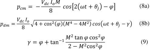
𝑝𝑐𝑚= − 𝑉𝑑𝑐 𝐼𝑜𝑀
8 𝑐𝑜𝑠[2(𝜔𝑡 + 𝜃𝑗) − 𝜑] (8a)
𝑝𝑑𝑚=𝑉𝑑𝑐 8𝐼𝑜√4 + cos2(𝜑)(𝑀4− 4𝑀2) 𝑐𝑜𝑠(𝜔𝑡 + 𝜃𝑗− 𝛾) (8b)
𝛾 = 𝜑 + tan−1𝑀2tan 𝜑 cos2𝜑
2 − 𝑀2cos2𝜑 (9)
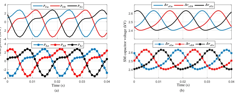
Equations (7) and (8) establish that the arm power is characterized by two components. The DM component pulsates with the fundamental frequency and appears in anti-phase in the upper and lower arms as a consequence of the load current being split differentially between the arms. The CM component pulsates at twice the fundamental frequency due to the different frequency alternation of both input and output powers. Both CM and DM power components are graphically demonstrated in Fig. 2 along with the total arm power, where it can be noticed that the DM power is the dominant component.
[image:3.612.341.532.51.196.2] [image:3.612.336.525.232.558.2]Due to the dual frequency alternation of the MMC arm powers, capacitor voltage-fluctuation has both CM and DM voltage-ripple components alternating at twice the fundamental frequency and at the fundamental frequency, respectively, as demonstrated by (10).
Fig. 2 MMC arm power components. (𝑉𝑑𝑐= 25 kV, 𝐼𝑜= 500 A, M = 0.75,
and 𝜑 = 35⁰).
(a)
(b)
Fig. 3 Relation curves of capacitor voltage-ripple at constant 𝑀/𝜔 versus operating frequency and output current for (a) CM component and (b) DM component. (C = 3 mF, 𝑉𝑐= 2.5 kV, and 𝜑 = 35⁰)
∆𝑣𝑐𝑈𝑗= −∆𝑉𝑐 𝑐𝑚
2 𝑠𝑖𝑛[2(𝜔𝑡 + 𝜃𝑗) − 𝜑] +∆𝑉𝑐 𝑑𝑚
2 𝑠𝑖𝑛(𝜔𝑡 + 𝜃𝑗− 𝛾)
(10a)
∆𝑣𝑐𝐿𝑗= −∆𝑉𝑐 𝑐𝑚
2 𝑠𝑖𝑛[2(𝜔𝑡 + 𝜃𝑗) − 𝜑] −∆𝑉𝑐 𝑑𝑚
2 𝑠𝑖𝑛(𝜔𝑡 + 𝜃𝑗− 𝛾)
(10b)
where ∆𝑣𝑐 and ∆𝑉𝑐 are the capacitor voltage-variation and the
absolute peak-to-peak variation of SM capacitor voltage-ripple, respectively.
%
Δ
Vc
cm
/
Vc
Output c urre
nt (A) Frequenc
y (Hz)
Frequenc y (Hz) Outp
ut curre nt (A)
%
Δ
Vc
d
m
/
[image:3.612.50.297.452.534.2]Fig. 4 Circuit diagram for the proposed MMC configuration feeding a three-phase machine.
The magnitudes of the peak-to-peak capacitor voltage-ripple due to CM and DM components are [20], [24]:
∆𝑉𝑐 𝑐𝑚= 𝐼𝑜𝑀
8𝜔𝐶 (11a)
∆𝑉𝑐 𝑑𝑚= 𝐼𝑜
4𝜔𝐶√4 + cos2(𝜑)(𝑀4− 4𝑀2) (11b)
Fig. 3 shows the 3-D curves of the normalized capacitor voltage ripple due to both the CM and DM components, varied with both operating frequency and output current, while the ratio 𝑀/𝜔 is maintained constant as a requirement of constant motor torque condition. Fig. 3a elucidates that the CM component has a slight effect on the capacitor voltage-ripple only with load current increase. That is, for a 1000 A current increase, the CM voltage ripple constitutes for ±2.5%, independent of the operating frequency. In contrast, Fig. 3b shows the DM component has a dominant influence in the SM capacitor voltage-ripple, as it is significantly increasing with both operating frequency reduction and output current increase.
III. PROPOSED MMCCONFIGURATION WITH RIPPLE POWER
DECOUPLING
The proposed MMC configuration employs magnetic chains equipped with power-decoupling channels linking adjacent-arm SMs. The power-decoupling channels are realized through HF transformer-based dc-dc converter units interfacing each adjacent SM of symmetrically modulated phase-arms as shown in Fig. 4, where a three-phase machine is fed through the proposed MMC drive configuration.
(a) (b)
Fig. 5 Phasor representation for MMC arm power components in the (a) fundamental-frequency domain and (b) second-order frequency domain.
A. Ripple Power Decoupling
Referring to (8), both the CM and DM power components symmetrically pulsate in the MMC’s three-phase arms, as represented in the frequency domain of Fig. 5. The symmetrical alternation of both power components results in a symmetrical fluctuation in the total arm power, as shown in Fig. 6a, which is consequently inherited in the corresponding SM capacitor voltage-variation, as presented in Fig. 6b. That is, the capacitor voltage-ripple of an upper-arm SM alternates with a ⅔𝜋 phase-shift to the capacitor voltage-ripple of adjacent SMs in other upper phase-arms, while it alternates in anti-phase to the capacitor voltage-ripple of an SM in corresponding lower arm due to the predominance of the DM component.
a b c Larm
Larm arm 1a
arm 2a
Three-phase machine
O
M
HB-SM arm 1b
arm 2b
arm 1c
arm 2c ia
ib
ic
2C S1
S2 +
-+
-2C Larm
Larm
Larm
Larm iUjvUj
Idc
SM =
=
SM =
=
SM =
=
SM = = SM =
=
SM =
=
SM = = SM = = SM = =
iLj vLj
SM = = SM = = SM =
=
SM = = SM
=
= SM
= =
SM =
=
SM =
=
SM =
= 2 Vdc
1
2 Vdc 1
φ pcm c
pcm a
pcm b ƴ
pdm a
pdm b
pdm c
φ pcm c
pcm a
pcm b ƴ
pdm a
pdm b
[image:4.612.57.556.52.344.2](a) (b)
Fig. 6 Symmetrical alternation of (a) three-phase arm powers and (b) three-phase SM capacitor voltages. (𝑉𝑑𝑐= 25 kV, 𝑉𝑐= 2.5 kV, C = 3 mF, 𝐼𝑜= 500 A, M
[image:5.612.54.565.285.404.2]= 0.75, and 𝜑 = 35⁰).
Fig. 7 A DHB-based power decoupling chain for three MMC adjacent-arm HB-SMs.
The basic idea of the active power decoupling is to divert the pulsating power from one specific energy storage component to another, through an active circuit. That is, the proposed MMC configuration redistributes the stored capacitive-energy among each three adjacent-arm SMs by allowing their ripple power to be transferred from one SM with an excess of capacitive stored energy to the other SMs, in a closed magnetic loop, to source the lack of energy there. With zero vectorial sum of symmetrical three-phase components, both the CM and DM power components are decoupled altogether in each chain link of adjacent-arm SMs. This results, ideally, in a ripple-free SM capacitor voltage profile.
B. Isolated Power Decoupling Channels
The dual active-bridge (DAB) converter is used in a variety of isolated dc-dc power conversion applications [25]. It has the merit of achieving high density bidirectional power transfer with galvanic isolation, soft-switching of semiconductor devices, and modular structure. The half-bridge version of such a converter, denoted as a dual half-bridge (DHB), requires half the number of switching devices as the full-bridge version, offering the benefits of low device count, reduced size, and operation with zero steady-state dc offset of transformer magnetizing current [26], [27]. In this paper, the DHB converter is employed as a dc-dc energy-exchange unit that achieves energy rebalancing for MMC SMs. A detailed
circuit diagram for one of the magnetic chains linking adjacent-arm SMs, shown in Fig. 4, is further illustrated in Fig. 7, where three HB-SMs are interconnected together through three DHB converters.
The DHB converter is composed by a pair of voltage-fed HB inverters interfaced through an HF transformer. The transformer turns ratio is unity since the dc-dc conversion is only employed for energy balancing between bridge sides at the same voltage level. DHB parasitic components are exploited to achieve some operational characteristics, where the leakage inductance of the HF transformer is employed as an energy transfer element between the dc capacitors, while the output capacitance of switching devices is used to realize soft-switching operation.
1. DHB Principle of Operation
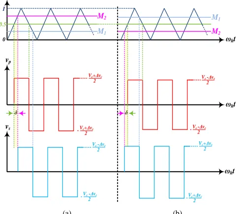
Since the DHB circuit creates a square-wave voltage on each side of the transformer, the power flow is controlled via the phase angle difference, 𝛿, between the primary and secondary voltage vectors. The most common approach for square-wave generation at both converter side is the phase-shift PWM in which each converter side is modulated with a triangular carrier signal of a frequency 𝜔ℎ and a constant duty ratio, D, of 50% (𝐷 = 0.5). Depending on the phase angle difference between the primary and secondary voltages, the amount of power transfer is [20]:
A
rm
p
o
w
er
(
M
W
)
Time (s)
S
M
c
a
p
a
c
it
o
r
v
o
lt
a
g
e
(
k
V
)
Time (s)
S1
S2
+
-+
-2C
2C
S1
S2
+
-+
-2C
2C
MMC HB-SM phase leg c
MMC HB-SM phase leg b
MMC HB-SM phase leg a
S1
S2
+
-+
-2C
2C
v1a
v2a
v1b
v2b v2c
v1c
DHB converter
1 : 1
Spʽ
Sp
Ssʽ
Ss
vp vs
iT
DHB converter
1 : 1
Spʽ
Sp
Ssʽ
Ss
vp vs
iT
DHB converter
1 : 1
Spʽ
Sp
Ssʽ
Ss
vp vs
𝑃 =𝑉𝑐
2𝛿(𝜋 − |𝛿|)
8𝜋2𝑓 ℎ𝐿
(12)
where L is the transformer leakage inductance and 𝑓ℎ is the DHB switching frequency.
To generate a phase difference 𝛿 between both DHB converter sides, two modulation signals are defined as follows [22].
𝑀1= 𝐷 − 𝛿
𝜋 (13a)
𝑀2= |1 − 𝑀1| (13b)
According to the sign of δ, bidirectional power can be transferred between DHB converter sides as illustrated in Fig. 8, where 𝑣𝑝 and 𝑣𝑠 are the voltages applied on the primary and
secondary transformer sides respectively.
2. DHB Soft Switching
DAB converters offer natural zero-voltage-switching (ZVS) transitions for the turn-on of all devices. A snubber capacitor should be connected across each switching device to extend the ZVS action to the turn-off instants. The ZVS condition for both switching devices of each HB is that the net current leaving the leg pole (middle access-point of the leg) lags the voltage of the pole. With the necessity of inserting a dead time between switching devices in the same bridge leg, the net leg output current should not change direction during the dead time until the opposite switching device is turned on. During the dead time, this current charges one snubber capacitor and discharges the other in the same leg, resulting in a soft 𝑑𝑣 𝑑𝑡⁄ . For turn-on ZVS, each switching device at each bridge side should have a negative current just before turning on, such that the anti-parallel diode is conducting, while the voltage across the switching device is almost zero. On the other side, when the switching device is turned off, the voltage across the snubber capacitor is almost zero and the switching device current will divert to the snubber capacitor, which slightly increases the snubber capacitor voltage at the turn-off instant. Since the proposed MMC configuration employs DHB modules with a unity voltage conversion ratio, ZVS operation is ensured for any loading condition [25].
C. Operation at Zero Motor-Speed/frequency
In a conventional MMC topology, the unidirectional current through MMC arms during near zero frequency operation results in a unidirectional change in SM capacitor voltage, leading to extreme capacitor voltage-ripple. In contrast, the proposed MMC-DHB configuration is prominently advantageous being able to efficiently operate at near zero frequency, that is, driving a machine from a full load torque standstill condition, with an enhanced SM capacitor voltage ripple-profile. At near zero frequency, the CM power in the different MMC arms is almost zero as a consequence of the power at both input and output ports being dc. Also, the DM symmetrical power components pulsating in the MMC arms are counter-balanced within the magnetic power-decoupling chains interfacing each group of adjacent-arm SMs.
(a) (b)
Fig. 8 Sketch of the phase-shift PWM of a DHB converter for bidirectional power transfer. (a) Positive phase-shift angle and (b) Negative phase-shift angle.
IV. CONTROL ALGORITHMS
In this section, the control schemes applied in the operation of the proposed MMC-DHB system as a variable-speed motor drive are illustrated. A block diagram for the overall control algorithm is shown in Fig. 9. It is divided into three main parts: a) motor control, b) MMC control, and c) the DHB power-channels control. Each part of the control system is briefly described in the following subsections. The outputs of the overall control algorithm are the switching commands for both MMC SMs and the DHB power channels.
A. Motor Control
The field-oriented control (FOC) scheme is applied to control the operational characteristics of the induction motor. As shown in the block diagram of Fig. 9, the FOC employs two control loops for both the machine torque and flux, implemented in the 𝑑𝑞 rotating frame, where two reference values for motor speed and flux are fed to the FOC scheme to generate the commanded values of torque- and flux-producing components of the stator current (𝑖∗𝑞and 𝑖∗𝑑). The reference current components are processed through two independent pairs of proportional integral (PI) controllers to generate two sets of reference voltage vectors (𝑣∗𝑞and 𝑣∗𝑑). These vectors are used to generate a set of three-phase reference voltages (𝑣∗𝑎, 𝑣∗𝑏, and 𝑣∗𝑐), that are utilized in the MMC modulation
as will be explained.
B. MMC Control
Each MMC phase-leg is controlled by a modulator that commands a varying number of SMs to be inserted at each time instant according to a phase disposition PWM scheme. Each modulator operates according to a sinusoidal reference input signal which depends on the motor control requirements. To maintain all of the MMC paralleled phase-legs balanced, a capacitor voltage balancing algorithm in addition to a CM current control scheme are applied as follows.
vp
δ
vs
2 Vc -Δvc
2 Vc -Δvc
-2 Vc+Δvc
2 -Vc+Δvc
ωht
ωht 2
Vc+Δvc
2 Vc+Δvc -
2 Vc -Δvc
2 -Vc -Δvc
δ 0.5
M1
M2 M1
M2
1
[image:6.612.318.559.53.271.2]Fig. 9 Control block diagram for the proposed MMC-DHB motor drive system.
1. Capacitor Voltage Balancing
SM capacitor voltage balancing is maintained by a selection mechanism based on capacitor voltage measurements at each switching instant. This mechanism sorts the SM capacitor voltages, and then decides which individual SM be inserted or bypassed, according to the arm current direction [28].
2. CM Current Regulation
A closed-loop control scheme for even-harmonics suppression of the CM current is implemented as introduced in [23], with the advantage of being independent of the SM capacitor voltage balancing. The controller consists of paralleled resonant controllers with the resonant frequency set at the even harmonics. Since the second- and fourth-order harmonics are the most dominant components in the CM current, only two proportional resonant (PR) controllers are utilized and tuned at 2𝜔𝑜 and 4𝜔𝑜, where 𝜔𝑜 is the fundamental angular frequency. The reference CM current is set to zero, while the outputs of the paralleled PR controllers are added together and fed to the MMC modulator as correction parameters for the three-phase reference signals.
C. DHB Control
The control of the DHB modules is ultimately to track both the level and direction of power exchange within each chain of interfaced MMC SMs, which rebalances the stored capacitive energy among the SMs. To ensure each SM capacitor voltage is ripple-free, a control loop employing a PI controller is implemented for each DHB module. The PI controller sets the voltage difference of each DHB primary- and secondary-side capacitor pair to zero, providing the necessary phase angle
difference, 𝛿∗, which is utilized as an input to the DHB modulator. Accordingly, the DHB modulator generates the control signals 𝑀1 and 𝑀2, as given by (13), such that they are
compared with a triangular carrier signal to generate the DHB switching signals (𝑆𝑝 𝐷𝐻𝐵 and 𝑆𝑠 𝐷𝐻𝐵), resulting in square wave voltages at both sides of the DHB module, shifted by the commanded angle 𝛿∗. With a fast and adequate modulation of the MMC arms, the same phase angle difference is utilized for all the 𝑁 power channels located at the same arm. That is, in the DHB control blocks of Fig. 9, the sum of the SM capacitor voltages of the upper arm of phase a (∑ 𝑣𝑐𝑈𝑎), are subtracted from that of the upper arm of phase b (∑ 𝑣𝑐𝑈𝑏) to control the
power flow through the DHB modules interconnecting the upper SMs of both phase a and b. The low-pass filter (LPF) is utilized to remove any harmonic wave distortion. The same control loop is repeated for each set of DHBs interfacing the SMs of two adjacent arms, where six PI controllers are employed to control all DHB modules.
V. DISCUSSION
The proposed approach in this paper employs power decoupling chain-links based on DHB units acting as SM energy balancers. In the MMC-DHB configuration shown in Fig. 4 (denoted as configuration 1), each magnetic chain link interfaces three MMC SMs through three DHB units. Therefore, the total number of employed DHB units is equal to the total number of MMC SMs.
A. DHB Rating
Although the proposed approach entirely decouples the SM ripple power (both CM and DM components), the decoupled speed controller iq* PI -+ -+ id* PI -+ vq* vd* dq abc *
ωr va*
vb* vc* abc dq ia ib ic id iq speed sensor ωr Ɵ current model Induction motor flux controller * ѱr speed command flux command MMC modulation SU MMC SL MMC Ɵ MMC-DHB system
-+ control signals
generation PI * LPF vcUa DHB modulation M1 M2 Sp DHB Ss DHB
icm j=0* +- +
+
icm j SM capacitor
voltage balancing algorithm
+ +
iu j iL j
power can be approximated as the DM power, being the major contributor in the arm ripple power. That is, the maximum SM decoupled power can be calculated from (8b), as:
𝑃𝑆𝑀𝑚𝑎𝑥 = 𝑃𝐷𝑀𝑚𝑎𝑥
𝑁 =
𝑉𝑑𝑐 𝐼𝑜
4𝑁 (14)
where 𝑃𝑆𝑀𝑚𝑎𝑥 and 𝑃𝐷𝑀𝑚𝑎𝑥 are the peak values of the decoupled SM power and the DM arm power, respectively. Since each SM capacitor is shared between two DHB units, the SM ripple power can be transferred through two power paths. The DHB control algorithm limits the maximum power transferred through each DHB unit to be equal to half the SM decoupled power. That is, each DHB unit is rated at half the SM power as given by (15), where 𝑃𝐷𝐻𝐵𝑚𝑎𝑥 is the peak value of the power transferred through each DHB unit.
𝑃𝐷𝐻𝐵𝑚𝑎𝑥= 𝑃𝑆𝑀𝑚𝑎𝑥
2 =
𝑉𝑑𝑐 𝐼𝑜
8𝑁 (15)
Since the voltage applied on both transformer windings is
½𝑉𝑐, the maximum transformer current, 𝐼𝑇𝑚𝑎𝑥, is calculated as:
𝐼𝑇𝑚𝑎𝑥=
2𝑃𝐷𝐻𝐵𝑚𝑎𝑥
𝑉𝑐 =
𝐼𝑜
4 (16)
Therefore, the voltage rating of the DHB switching devices is
𝑉𝑐, while the current rating is ¼𝐼𝑜.
B. MMC-DHB Configuration with Reduced DHB Units
A variation of the MMC-DHB configuration can be realized as shown in Fig. 10, (denoted as configuration 2), where the number of the employed DHB units is reduced. In this alternative configuration, each three adjacent-arm SMs are linked through a magnetic chain equipped with two DHB units. Referring to Fig. 10, the SMs of the middle phase-leg are explicitly interfaced with the SMs of both the right and left phase-legs through two DHB modules. This keeps SMs at the right and left phase-legs implicitly connected through the corresponding middle phase-leg’s SMs. Therefore, the number of employed DHB units in this alternative configuration is reduced to 2 3 ⁄ the total number of the MMC SMs. However, each DHB module should be rated at the full SM decoupled power, which doubles the current stress of the DHB switching devices, compared to configuration 1. Table I gives a quantitative assessment for the two proposed MMC-DHB configurations, in addition to that presented in [21].
It is worth mentioning that both configurations give the same power-decoupling performance which results in same SM capacitor voltage-ripple profile. However, configuration 1 is preferred with high power drives, since it implies lower power through the DHB modules. Configuration 2 is recommended at lower power ratings, where the volume of the drive system is highly prioritized. With a 166 kW indicating the maximum power rating of practical implementation of HF transformers [29], MMC-DHB configuration 1 can be utilized to drive 20 MW machine, with 10 MMC SMs per arm. These parameters are selected for the simulation case study models, as in Section VI.
Fig. 10 An alternative structure of the proposed MMC configuration with reduced number of DHB modules.
TABLEI
COMPARISON BETWEEN DIFFERENT MMC-DHBCONFIGURATIONS
Config. 1 Config. 2 Config. in [21]
Number of DHB modules 6N 4N 3N
DHB rated power ½𝑃𝑆𝑀 𝑃𝑆𝑀 𝑃𝑆𝑀
Semiconductors rated voltage ½𝑉𝑐 ½𝑉𝑐 ½𝑉𝑐
Semiconductors rated current ¼𝐼𝑜 ½𝐼𝑜 ½𝐼𝑜
Decoupled ripple component CM and DM
CM and
DM DM
VI. VERIFICATION
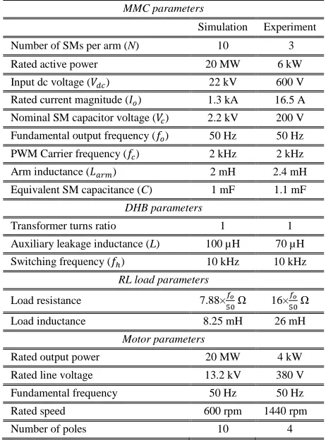
The performance of the proposed MMC topology with the DHB power decoupling scheme was investigated using MATLAB/SIMULINK simulation models, in addition to experimentation using a downscaled laboratory prototype. In both verification methods, steady-state and dynamic performances are examined with different operating scenarios, with the parameters listed in Table II.
A. Simulation Verification
In the simulation study, the MMC-DHB configuration 1 is implemented, where a chain link of three DHB modules interfaces each adjacent-arm SM. The steady-state fundamental waveforms for the MMC system at rated parameters are shown in Fig. 11, while Fig. 12 shows the waveforms of the DHB balancing scheme, where the MMC-DHB system is supplying a three-phase RL load. In Fig. 11, both three-phase line voltages and load currents show high-quality sinusoidal waveforms. The arm currents have been controlled to be free of both second- and fourth-order harmonics, as explained in Section IV, where the PR controllers are tuned at 100 Hz and 200 Hz, respectively, resulting in a near dc CM current.
a b c arm 1a arm 2a SM SM SM SM SM SM Three-phase machine O
M
= = = = = = = = = = = = arm 1b arm 2b SM SM SM SM SM SM = = = = = = = = = = = = arm 1c arm 2c SM SM SM SM SM SM ia ib ic Larm Larm Larm Larm Larm Larm2 Vdc
1 2 Vdc
[image:8.612.315.571.46.258.2]TABLEII
SIMULATION AND EXPERIMENTATION PARAMETERS
MMC parameters
Simulation Experiment
Number of SMs per arm (N) 10 3
Rated active power 20 MW 6 kW
Input dc voltage (𝑉𝑑𝑐) 22 kV 600 V
Rated current magnitude (𝐼𝑜) 1.3 kA 16.5 A
Nominal SM capacitor voltage (𝑉𝑐) 2.2 kV 200 V
Fundamental output frequency (𝑓𝑜) 50 Hz 50 Hz
PWM Carrier frequency (𝑓𝑐) 2 kHz 2 kHz
Arm inductance (𝐿𝑎𝑟𝑚) 2 mH 2.4 mH
Equivalent SM capacitance (C) 1 mF 1.1 mF
DHB parameters
Transformer turns ratio 1 1
Auxiliary leakage inductance (L) 100 µH 70 µH
Switching frequency (𝑓ℎ) 10 kHz 10 kHz
RL load parameters
Load resistance 7.88×𝑓𝑜
50 Ω 16× 𝑓𝑜 50 Ω
Load inductance 8.25 mH 26 mH
Motor parameters
Rated output power 20 MW 4 kW
Rated line voltage 13.2 kV 380 V
Fundamental frequency 50 Hz 50 Hz
Rated speed 600 rpm 1440 rpm
Number of poles 10 4
Different samples of capacitor voltage for SMs in upper and lower arms are shown balanced around 2.2 kV with ±10% voltage ripple. The CM voltage, measured at the terminals of the three-phase load is shown to alternate with near 1 kV amplitude. The supply current is near constant with only switching harmonics, due to the suppression of even harmonics in the arm currents.
Fig. 12 shows the switching waveforms of one DHB module interfacing a pair of upper-arm SMs located in phase a and b, within two switching cycles in different time spans. The voltages across the primary and secondary transformer windings are shown, along with the transformer current. The amount of power transfer is in direct proportion to the magnitude of the phase angle difference, while forward or reverse power transfer is designated depending on the polarity of 𝛿.
To highlight the effectiveness of the employed power decoupling scheme, the simulation was performed at low operating frequencies, while the load resistance was varied linearly with the frequency reduction to maintain the load current constant at the rated value. The DHB scheme is initially deactivated, and the MMC system behaves as a conventional MMC, (the results are recorded for one operating cycle). Then, the DHB scheme is activated, and the system performance is monitored for two operating cycles. This is shown in Figs. 13 and 14 for operation at 10 Hz and 5 Hz, respectively. Common to both cases is that the quality of both line voltages and load currents is enhanced with the activation of the power decoupling scheme. Also, with the fundamental
Fig. 11 Simulation results for the MMC configuration at rated parameters.
and second-order arm powers decoupled in the three-phase MMC legs, the arm currents are near even-harmonics-free without a harmonic suppression control algorithm. SM capacitor voltages exhibit significant ripple reduction with the DHB energy balancing scheme, where at 10 Hz, the voltage ripple is reduced from ±52% to ±5%, and from ±90% to
v
abv
bcv
cai
ai
bi
ci
Uai
Lai
cm av
cUa andv
cLav
cm [image:9.612.57.288.79.391.2]Fig. 12 Simulation results for the switching waveforms of the phase-shift DHB converter at rated parameters.
Fig. 13 MMC performance at 10 Hz before and after DHB power decoupling scheme activation.
±5% at 5 Hz. Although operation with such extreme voltage ripple percentages without DHB scheme incorporation is impractical, it gives clear indication of the significant reduction achieved in SM capacitance when the power decoupling scheme is employed.
Fig. 14 MMC performance at 5 Hz before and after DHB power decoupling scheme activation.
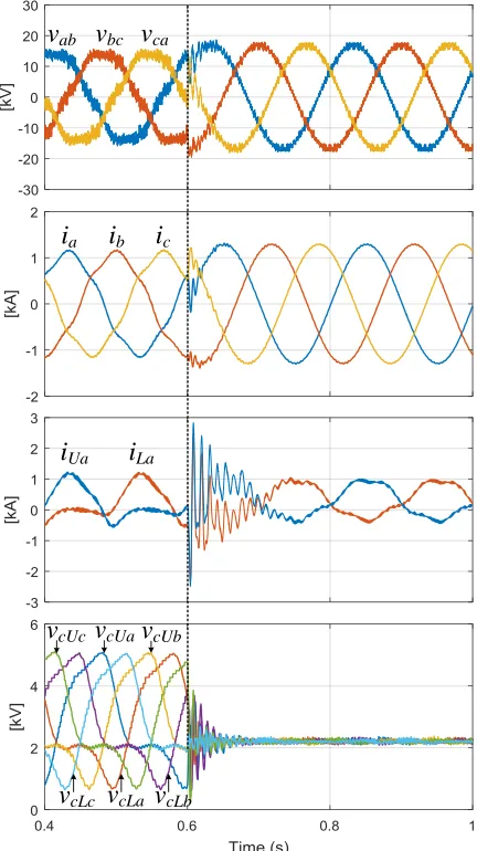
Fig. 15 shows the dynamic performance of the proposed MMC-DHB system when driving a three-phase induction machine from standstill to the rated speed, at the rated torque operating condition. The motor currents maintain a high-quality sinusoidal profile within the entire speed range.
vs
vp
δ
vs
vp
δ
vp
vs
δ
iT
iT
iT
v
abv
bcv
cai
ai
bi
ci
Uai
Lav
cUav
cUbv
cLav
cLbv
cUcv
cLcv
abv
bcv
cai
ai
bi
ci
Uai
Lav
cUav
cUbv
cLav
cLbv
cUc [image:10.612.326.542.252.637.2] [image:10.612.65.284.255.639.2]Fig. 15 Dynamic performance of the proposed MMC system driving a 20 MW induction machine from standstill to the rated speed.
The SM capacitor voltage ripple is limited within a very narrow ripple band, even at near zero frequency. The CM voltage swings with a 1.5 kV amplitude. The supply current is
continuous with only switching harmonics, while it is slightly reduced when the motor reaches the steady-state at the rated speed.
i
ai
bi
ci
Uai
Lav
cUa andv
cLav
cmFig. 16 Hardware view of the experimental prototype.
B. Experimental Assessment
The experimental downscaled prototype MMC-DHB system comprises a three-phase MMC rated at 6 kW, 360 V, with 3 SMs per arm and supplied from a 600 V dc-link. To reduce the number of employed SM balancers, configuration 2 is adopted for the MMC energy balancing scheme, where each three adjacent-arm SMs are interfaced through two DHB modules, each employing a nanocrystalline core-based HF transformer with a core saturation flux density of 1.2 T and a unity turns ratio. The control system is implemented in TMS320F28335 DSPs. The experimental setup is shown in Fig. 16. Both steady-state and dynamic performance of the proposed MMC-DHB system are examined under different operating scenarios. Steady-state results at different operating frequencies were recorded while the MMC-DHB system is supplying three-phase RL load, where the resistance was varied linearly in proportional to the frequency variation to emulate constant Volt/Hertz operation. Dynamic results were obtained during starting of a three-phase induction machine from standstill to the rated speed. Experimental waveforms are presented in Figs. 17 to 22.
1. Steady-State Performance
Fig. 17 shows the fundamental waveforms of the MMC at the rated parameters of Table II, where the MMC is supplying a three-phase RL load at 50 Hz. The phase voltage waveforms are shown with respect to the virtual ground of the dc-link midpoint, so have seven voltage-levels between ±300 V. The CM voltage is shown as the average of the measured phase voltages with 70 V amplitude. The three-phase line voltages and corresponding load currents are shown to be balanced. Arm currents of phase a and its CM current are shown, where the arm currents are free of dominant even-harmonics due to
CM current regulation, resulting in a near dc CM current. Fig. 17 Experimental waveforms of the MMC system at rated parameters.
DC input voltage source `
scope
scope power supplies
arm inductors
gate-drive circuits
3 SM s arm current transducer
DHB modu le dead-time circuit
3 S
M
s a
rm
voltage transduce rs
[5.0 ms/div]
vao vbo vco
vcm
[200.0 V/div]
[5.0 ms/div]
vab vbc vca
[200.0 V/div]
[5.0 ms/div]
ib
ia ic
[10.0 A/div]
[5.0 ms/div]
icm a
iUa iLa
[image:12.612.315.557.307.690.2](a) (b)
Fig. 18 Capacitor voltage fluctation at 50 Hz when the DHB scheme is (a) deactivated and (b) activated.
[image:13.612.61.559.49.150.2](a) (b)
Fig. 19 Capacitor voltage fluctation at 10 Hz when the DHB scheme is (a) deactivated and (b) activated.
[image:13.612.78.554.177.276.2](a) (b)
Fig. 20 Capacitor voltage fluctation at 5 Hz when the DHB scheme is (a) deactivated and (b) activated.
(a) (b)
Fig. 21 Capacitor voltage fluctation at 1 Hz when the DHB scheme is (a) deactivated and (b) activated.
Figs. 18-21 practically assess the influence of the DHB power decoupling scheme by presenting SM capacitor voltage fluctuation at different operating frequencies when the DHB scheme is deactivated, then operational. Three samples of upper-arm SM capacitor voltages are shown for the three phase-legs. At 50 Hz, Fig. 18 shows that capacitor voltage ripple is reduced from ±5.6% to ±2.5% with incorporation of the DHB scheme. A significant reduction in capacitor voltage ripple, with the activation of the energy balancing scheme occurs at reduced operating frequencies, where at 10 Hz (see Fig. 19) the capacitor voltage ripple decreases from ±11.25% to ±4.25%, while at 5 Hz (see Fig. 20) the voltage ripple decreases from ±21% to ±5.25%. At 1 Hz, Fig. 21a shows that the capacitor voltage ripple using a conventional MMC is extreme,±67%, possibly threatening the safe operation of the
MMC components and results in a loss of system controllability. The DHB scheme efficiently restores the MMC balance as shown in Fig. 21b, where the capacitor voltage ripple is ±6%. Although the capacitor voltage ripple with the DHB scheme is in operation slightly increases with frequency reduction, the ripple is maintained within tolerated limits at all operating frequencies.
Fig. 22 shows the waveforms of one DHB converter at rated parameters. The square wave voltages across the primary and secondary sides of the HF transformer are shown along with the transformer current at a time instant when the primary-side HB is leading the secondary-side HB. The switching waveforms across the IGBTs are shown to illustrate the ZVS. Both gate-to-emitter (𝑣𝐺𝐸) and collector-to-emitter (𝑣𝐶𝐸)
voltages are shown at the DHB converter primary side.
[5.0 ms/div]
vcUa vcUb vcUc
[50.0 V/div]
[5.0 ms/div] [50.0 V/div]
vcUa,vcUb, vcUc
[20.0 ms/div] [50.0 V/div]
vcUa vcUb vcUc
[20.0 ms/div] [50.0 V/div] vcUa,vcUb, vcUc
[50.0 ms/div] [50.0 V/div] vcUa vcUb vcUc
[50.0 ms/div] [50.0 V/div] vcUa,vcUb, vcUc
[200.0 ms/div] [50.0 V/div]
vcUa vcUb vcUc
[image:13.612.68.555.302.403.2] [image:13.612.57.571.428.532.2]Fig. 22 DHB converter switching waveforms at rated parameters.
Fig. 23 Dynamic performance of the proposed drive system when starting an induction motor from standstill to the rated speed at rated torque.
2. Dynamic Performance
The dynamic performance of the proposed MMC-DHB system is experimentally examined as a motor acceleration process from standstill to the rated speed, at the full load torque throughout, as shown in Fig. 23. The phase voltage and motor current are recorded from phase a, where the MMC system, with the aid of the DHB power decoupling scheme, is able to generate a near dc voltage as briefly as required by the motor at zero speed with an acceptable SM capacitor voltage ripple profile. Sample upper and lower capacitor voltages are shown to have a near constant ripple profile within the entire speed range, where the ripple voltage is limited within ±5%.
VII. CONCLUSION
In this paper, a decoupling approach for MMC capacitor voltage ripple compensation has been proposed for three-phase MMC-fed variable speed drives. The approach employs magnetic chain links equipped with DHBs to interface adjacent-arm SMs. Based on their symmetrical alternation, the ripple powers of the MMC phase legs are decoupled altogether within each chain of three magnetically-coupled SMs, where the ripple power is transferred from one SM to another to compensate for the energy imbalance. This results in a significant enhancement in the SM capacitor voltage profile, where the voltage ripple is brought down to a very narrow band, which inherently reduces the even-order harmonics in the CM current. A significant reduction in the SM capacitance is possible since the voltage ripple can be considered near constant, independent of the operating frequency. The proposed MMC-DHB configuration is efficiently able to drive multi-megawatt machines continuously at low operating speeds, from standstill condition, at the rated torque. Two MMC-DHB configuration variations have been presented, each with a different number of DHB balancing units, both able to entirely decouple the fundamental and the second-order ripple power of the MMC arms. One drawback of the proposed MMC-DHB approach is that the system reliability is affected, compared to a traditional MMC system, since the failure of any MMC SM implies deactivating the other SMs and DHB balancers at the same level within the associated chain. The mathematical analysis of the proposed approach has been presented, and the MMC-DHB drive system performance has been verified through simulation and experimentation, at different operating scenarios.
REFERENCES
[1] S. Debnath, J. Qin, B. Bahrani, M. Saeedifard, and P. Barbosa, “Operation, control, and applications of the modular multilevel converter: A review,” IEEE Trans. Power Electron., vol. 30, no. 1, pp. 37–53, Jan. 2015.
[2] A. Bendre, G. Venkataramanan, D. Rosene, and V. Srinivasan, “Modeling and design of a neutral-point voltage regulator for a three-level diode clamped inverter using multiple-carrier modulation,” IEEE Trans. Ind. Electron., vol. 53, no. 3, pp. 718–726, Jun. 2006.
[3] I.-D. Kim, E.-C. Nho, H.-G. Kim, and J. S. Ko, “A generalized Undeland snubber for flying capacitor multilevel inverter and converter,” IEEE Trans. Ind. Electron., vol. 51, no. 6, pp. 1290–1296, Dec. 2004.
[4] S. Sirisukprasert, J. S. Lai, and T. H. Liu, “Novel cascaded multilevel converter drive system with minimum number of separated DC sources,” in Proc. IEEE PESC, Vancouver, BC, Canada, Jun. 17–22, 2001, pp. 1346–1350.
[5] A. Lesnicar and R. Marquardt, “An innovative modular multilevel converter topology suitable for a wide power range,” in Proc. IEEE PowerTech. Conf., Bologna, Italy, Jun. 23–26, 2003, vol. 3.
[6] A. Korn, M. Winkelnkemper, and P. Steimer, “Low output frequency operation of the modular multi-level converter”, 2010 IEEE Energy Conversion Congress and Exposition, Atlanta, GA, 2010, pp. 3993-3997.
[7] S. Debnath, J. Qin and M. Saeedifard, “Control and Stability Analysis of Modular Multilevel Converter under Low-Frequency Operation,” IEEE Trans. Ind. Electron, vol. 62, no. 9, pp. 5329-5339, Sept. 2015. [8] J. Kolb, F. Kammerer, M. Gommeringer, and M. Braun, “Cascaded
control system of the modular multilevel converter for feeding variable-speed drives,” IEEE Trans. Power Electron., vol. 30, no. 1, pp. 349–357, Jan. 2015.
[9] A. Antonopoulos, L. Angquist, S. Norrga, K. Ilves, L. Harnefors, H.-P. Nee, “Modular multilevel converter ac motor drives with constant torque [20.0 µs/div]
vp(100.0 V/div)
iT(10.0 A/div) vs (100.0 V/div)
[20.0 µs/div]
vGE2(20.0 V/div)
vCE1(200.0 V/div)
vCE2 (200.0 V/div)
vGE1(20.0 V/div)
vao
[1.0 s/div] [200.0 V/div]
ia
[1.0 s/div] [5.0 A/div]
vcUa vcLa
from zero to nominal speed,” IEEE Trans. Ind. Appl., vol. 50, no. 3, pp. 1982–1993, May/Jun. 2014.
[10] K. Wang, Y. Li, Z. Zheng, and L. Xu, “Voltage balancing and fluctuation-suppression method of floating capacitors in a new modular multilevel converter,” IEEE Trans. Ind. Electron., vol. 60, no. 5, pp. 1943–1954, May 2013.
[11] B. Li, S. Zhou, D. Xu, R. Yang, D. Xu, C. Buccella, and C. Cecati, “An improved circulating current injection method for modular multilevel converters in variable-speed drives” IEEE Trans. Ind. Electron., vol. 63, no. 11, pp. 7215-7225, Nov. 2016.
[12] A. Antonopoulos, L. Ängquist, L. Harnefors and H. P. Nee, “Optimal Selection of the Average Capacitor Voltage for Variable-Speed Drives with Modular Multilevel Converters,” IEEE Trans. Power Electron., vol. 30, no. 1, pp. 227-234, Jan. 2015.
[13] B. Tai; C. Gao; X. Liu; Z. Chen, “A Novel Flexible Capacitor Voltage Control Strategy for Variable-Speed Drives with Modular Multilevel Converters,” IEEE Trans. Power Electron., vol. 32, no. 1, pp. 128-141, Jan. 2017.
[14] Yang; B. Li; G. Wang; C. Cecati; S. Zhou; D. G. Xu; W. Yu, “Asymmetric mode control of MMC to suppress capacitor voltage ripples in low frequency low voltage condition,” IEEE Trans. Power Electron., vol. 32, no. 6, pp. 4219-4230, June 2017.
[15] A. Mertens and J. Kucka, “Quasi Two-Level PWM Operation of an MMC Phase Leg with Reduced Module Capacitance,” IEEE Trans. on Power Electron., vol. 31, no. 10, pp. 6765-6769, Oct. 2016.
[16] S. Du, B. Wu, K. Tian, N. R. Zargari and Z. Cheng, “An Active Cross-Connected Modular Multilevel Converter (AC-MMC) for a Medium-Voltage Motor Drive,” IEEE Trans. Ind. Electron, vol. 63, no. 8, pp. 4707-4717, Aug. 2016.
[17] S. Du; B. Wu; N. Zargari; Z. Cheng, “A Flying-Capacitor Modular Multilevel Converter (FC-MMC) for Medium-Voltage Motor Drive,” IEEE Trans. Power Electron., vol. 32, no. 3, pp. 2081-2089, March 2017.
[18] Z. Kong; X. Huang; Z. Wang; J. Xiong; K. Zhang, "Active Power Decoupling for Submodules of Modular Multilevel Converter," IEEE Trans. Power Electron, vol. 33, no. 1, pp. 125-136, Jan. 2018.
[19] L. He, K. Zhang, J. Xiong, S. Fan, and Y. Xue, “Low-frequency ripple suppression for medium-voltage drives using modular multilevel converter with full-bridge submodules,” IEEE J. Emerg. Sel. Topics Power Electron., vol. 4, no. 2, pp. 657–667, June 2016.
[20] M. S. Diab, A. M. Massoud, S. Ahmed and B. W. Williams, "A Dual Modular Multilevel Converter With High-Frequency Magnetic Links Between Submodules for MV Open-End Stator Winding Machine Drives," IEEE Trans. Power Electron., vol. 33, no. 6, pp. 5142-5159, June 2018.
[21] L. He, K. Zhang, J. Xiong, S. Fan, X. Chen and Y. Xue, "New modular multilevel converter with power channels between upper- and lower arms suitable for MV drives," 2015 IEEE Applied Power Electronics Conference and Exposition (APEC), Charlotte, NC, 2015, pp. 799-805. [22] A. Zafeiropoulos, A. Antonopoulos and J. R. Svensson, "An
MMC-based topology using DHB power channels for load balancing in 50 Hz railway applications," 2017 IEEE Energy Conversion Congress and Exposition (ECCE), Cincinnati, OH, 2017, pp. 83-90.
[23] Z. Li, P. Wang, Z. Chu, H. Zhu, Y. Luo, and Y. Li, “An inner current suppressing method for modular multilevel converters,” IEEE Trans. Power Electron., Vol. 28, No. 11, pp. 4873-4879, Nov. 2013.
[24] M. S. Diab, B. W. Williams, D. Holliday, A. M. Massoud and S. Ahmed, "A modular multilevel converter with isolated energy-balancing modules for MV drives incorporating symmetrical six-phase machines," 2017 IEEE Energy Conversion Congress and Exposition (ECCE), Cincinnati, OH, 2017, pp. 2715-2722.
[25] M. H. Kheraluwala, R.W. Gascoigne, D.M. Divan and E. D. Baumann, “Performance characterization of a high-power dual active bridge dc-to-dc converter,” IEEE Trans. Ind. Applications, vol. 28, no. 6, pp. 1294-1301, Nov/Dec. 1992.
[26] H. Li, F. Z. Peng and J. S. Lawler, "A natural ZVS medium-power bidirectional DC-DC converter with minimum number of devices," IEEE Trans. Ind. Appl., vol. 39, no. 2, pp. 525-535, Mar/Apr 2003.
[27] F. Z. Peng, Hui Li, Gui-Jia Su and J. S. Lawler, "A new ZVS bidirectional DC-DC converter for fuel cell and battery application," IEEE Trans. Power Electron., vol. 19, no. 1, pp. 54-65, Jan. 2004.
[28] A. Antonopoulos, L. Angquist, and H.-P. Nee, “On dynamics and voltage control of the modular multilevel converter,” 2009 13th
European Conference on Power Electronics and Applications,
Barcelona, 2009, pp. 1-10.
[29] M. Leibl, G. Ortiz and J. W. Kolar, "Design and Experimental Analysis of a Medium-Frequency Transformer for Solid-State Transformer Applications," IEEE J. Emerg. Sel. Topics Power Electron., vol. 5, no. 1, pp. 110-123, March 2017.
Mohamed S. Diab (S’09)received the B.Sc. (First Class Hons.) and M.Sc. degrees in electrical engineering from Alexandria University, Alexandria, Egypt, in 2012, and 2015, respectively. He is currently working toward the Ph.D. degree in electrical engineering at the University of Strathclyde, Glasgow, U.K. He was in the Department of Electrical Engineering, Alexandria University, where he was appointed as a Demonstrator in 2012 and as an Assistant Lecturer in 2015. He was with Spiretronic LLC, Houston, TX, USA, as a Research Engineer, from 2013 to 2015. His main research interests include medium-voltage applications, high-power electronic converters, renewable energy conversion systems, grid integration of distributed generators, and electric drives.
Ahmed M. Massoud (SM’11) received the B.Sc. (First Class Hons.) and M.Sc. degrees in electrical engineering from Alexandria University, Alexandria, Egypt, in 1997 and 2000, respectively, and the Ph.D. degree in electrical engineering from Heriot-Watt University, Edinburgh, U.K., in 2004. He is currently an Associate Professor at the Department of Electrical Engineering, College of Engineering, Qatar University. His research interests include power electronics, energy conversion, renewable energy and power quality. He holds five U.S. patents. He published more than 100 journal papers in the fields of power electronics, energy conversion, and power quality.
Shehab Ahmed (SM'12) received the B.Sc. degree from Alexandria University, Alexandria, Egypt, in 1999, and the M.Sc. and Ph.D. degrees from the Department of Electrical and Computer Engineering, Texas A&M University, College Station, TX, USA, in 2000 and 2007, respectively, all in electrical engineering. He was with Schlumberger Technology Corporation, Houston, TX, USA, from 2001 to 2007, where he was involved in downhole mechatronic systems. He is currently an Associate Professor with Texas A&M University at Qatar, Doha, Qatar. His research interests include mechatronics, solid-state power conversion, electric machines, and drives.