Numerical Study on AC Loss Properties of HTS
Cable Consisting of YBCO Coated Conductor for
HTS Power Devices
Shanshan Fu, Ming Qiu, Jiahui Zhu, Huiming Zhang, Jun Gong, Xin Zhao, Weijia Yuan, Jianbo Guo
Abstract—High-current high temperature superconducting (HTS) cables have been developed for use in HTS power devices. This paper presented the structures of HTS cables, including Conductor on Round Core (CORC) cable, Twisted Stacked-tape Conductor (TSTC) cable and Double coaxial cable. Subsequently, three dimensional (3D) finite element method numerical models were built to analyze the electromagnetic characteristics of the cables, and the critical current of the cables is about 380 Ampere @77 K, self-field. Using the T-A formulation, the numerical model assumed a sheet approximation for conductors, which shortened computational time. The T-A formulation were verified by experiments on a superconducting tape. Then HTS cables with different configurations were made, as functions of different transport current and background magnetic field, and different pitches of Double Coaxial Cable inner conducting layer. According to the results, the AC losses of Double coaxial cable and CORC cable decreased 40% than the TSTC cable with different transport current, and the Double coaxial cable AC loss decreased 20% than the CORC cable when background magnetic field was in the range of 20-60 mT. Conclusions obtained from this study will be helpful for understanding the AC loss properties of HTS cables and useful in design of HTS power devices (such as HTS transformer), using HTS cables.
Index Terms—AC loss, 3D FEM, Double coaxial cable.
I. INTRODUCTION
he development of fabrication technologies for long superconductors with high critical current densities has opened up new possibilities for high temperature superconductor applications. Yttrium Barium Copper Oxide (YBCO) coated conductors or Bismuth Strontium Calcium Copper Oxide (BSCCO) tapes are used as superconductor tapes [1-2]. Because of the higher current-carrying capacity for fusion magnets and HTS power devices, there are several HTS cable concepts being developed at companies and research institutions around the world, such as, Roebel
This project is supported by China State Grid Corporation science and technology project DG71-16-002, DG83-17-002, DG71-17-020 and 2017GW--04.
Shanshan Fu, Ming Qiu, Jiahui Zhu, Huiming Zhang, Jun Gong, Xin Zhao, Jianbo Guo are with the China Electric Power Research Institute, Beijing, 100192, China. Ming Qiu is the corresponding author (e-mail: [email protected]).
Weijia Yuan is with the University of Bath, Bath, BA2 7AY, United Kingdom.
Assembled coated conductor cables (RACC) [3-4], Conductor on Round Core cables (CORC) [5], Twisted Stacked-Tape Conductor cables (TSTC) [6], and Double coaxial cables [7]. These HTS cables are all presented in complex structures by twisting techniques, and the development of high current density, low AC loss and high stable cable has been ongoing.
This paper focused on the study of CORC cable, TSTC cable and Double coaxial cable. CORC cable has been mentioned by van der Lann in the study of irreversible degradation strain of superconducting tapes [4].The original idea for TSTC cable and Double coaxial cable was first mentioned by Takayasu M, and the longitudinal field of Double coaxial cable can enhance inner and outer cables enhance each other performance by more than 20% [7]. Compared to straight tapes, these cables have more complex structure, and thus numerical study of such cables becomes crucial. As simplified two-dimensional models cannot illustrate the detailed structure of HTS cables, in previous studies, three dimensional (3D) time-dependent electromagnetic models in the numerical study have been built by H-formulation, such as, the magnetization loss, magnetic shielding effects and end effects of short CORC cables are discussed by Jie Sheng et al. [8] and M Majoros et al. [9]. Francesco Grilli et al. computed the magnetization AC losses of a twisted superconductor and current repartition among the tapes in a cable [10-12]. However, H-formulation is very difficult to set the boundary imposing the transport current when symmetry couldn’t be used for dimensional reduction, and the high aspect ratio of superconducting tape results in huge mesh elements. T-A formulation uses a sheet to tackle the high aspect ratio problem of the HTS tape, and the computation regions are divided into the superconducting sheet using T formulation and the non-superconducting space using A formulation [13].
In this paper, 3D numerical models of HTS cables were proposed using T-A formulation, and electromagnetic characteristics were analyzed to calculate the AC losses of different cable transport currents and different background magnetic fields. In addition, AC loss properties with different inner conducting layer pitches of Double coaxial cable were analyzed to achieve the optimization of the Double coaxial cable, as well as the design of HTS power devices based on HTS cables.
II. METHODOLOGY
A. Structure of the HTS Cables
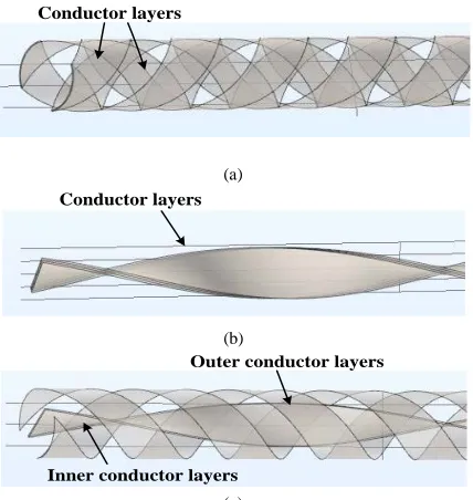
The structures of the HTS cables are shown in Fig. 1, with the copper former not shown in the figure. The CORC cable mainly included a copper former, and conductor layers which were helically wound with superconducting tapes. The TSTC cable was composed of twisting freestanding flat tapes along the stack axis. The Double coaxial cable was composed of copper former, and two different types of conductor layers mounted co-axially, with the inner conductor layer made of twisted stacked tapes and the outer conductor layer a helical winding tape, as in CORC [7].
Conductor layers
(a)
Conductor layers
(b)
Outer conductor layers
Inner conductor layers
(c)
Fig. 1. Structure of the HTS cables (a) CORC cable (b) TSTC cable (c) Double coaxial cable
B. Methodology of Numerical Model
The critical current of the HTS cables consisting of YBCO coated conductor is about 380 Ampere @77 K, self-field, and the detailed parameters of YBCO coated conductor and HTS Cables are listed in Table I. 1st conducting layer radius of CORC cable is equal to the outer conducting layer radius of Double coaxial cable. The superconducting coated conductor tape numbers of HTS cable are the same. The 3D geometry of Double coaxial cable with four superconducting tapes is shown in Fig. 2 (a).
air space
Superconducting tapes
0.0 0.2 0.4 0.6 0.8 1.0 0 20 40 60 80 100 Ic (A)
Magnetic field (T)
Perpendicular magnetic field Bper Parallel magnetic field Bpar
(a) (b)
Fig. 2. (a) The geometry of Double coaxial cable (CORC and TSTC cable aren’t presented in this Fig) (b) Ic-B (Bper, Bpar) curves obtained by experiment
TABLE I
PARAMETERS OF SUPERCONDUCTING TAPE AND HTSCABLE
Characteristics Item Value
HTS tape Manufacturer Superpower
Width 4 mm
Thickness 0.1 mm
Critical current 95 A @77 K, self-field CORC cable Radius of copper former 3 mm
Radius of 1st conductor layer 3.1 mm Tape number of 1st conductor layer 2
Pitch 20 mm
Radius of 2nd conductor layer 3.1 mm
Tape number of 2nd conductor layer 2
Pitch 20 mm
TSTC cable Tape number 4
Pitch 70 mm
Double coaxial
cable Radius of copper former 3 mm Radius of outer conductor layer 3.1 mm Tape number of outer conductor layer 2
Pitch 20 mm
Tape number of inner conductor layer 3.1 mm
Pitch 70 mm
The current vector potential T is the state variable solved in the superconducting region defined by the curl of current density as (1), T= [Tx, Ty, Tz], T can be written as T.n.
( .n ) ( .n )
( .n ) ( .n )
( .n ) ( .n )
y z y z x x z y z x z y x x y T T J T T J J T T ∂ −∂ ∂ ∂ =∂ −∂ ∂ ∂ ∂ ∂ − ∂ ∂ (1)
The current density is combined with the E-J power law as:
0 0 0 ( ) ( ) ( ) n norm x c c x y n norm y c c z n norm z c c J J E J J E J J E E J J E J J E J J = (2)
Where n is assumed to be 21, E0 is 10-4 Vm-1, and Ex, Ey, and Ez are the electric fields. In this paper Jc is the critical current density, and the relationship between Ic and perpendicular magnetic field Bper and parallel magnetic field
Bpar is shown in Fig. 2 (b). Ic(B) is implemented by the numerical interpolation in the model, and Jc(B)=Ic(B)/tape cross-section.
According to the Maxwell equation:
0
y
z x
y
x z
y x z
E
E B
y z t
B
E E
n n
z x t
E E B
[image:2.612.67.281.210.436.2] [image:2.612.49.297.607.718.2]In this paper the magnetic field B is solved by the traditional A formulation, where A is the magnetic vector potential, J is the current flowing in the superconducting sheet. The AC loss per cycle for a superconductor is calculated as:
/ 2
2 t norm norm
t s
Q= d
∫ ∫∫
J E dsdt (4)Where t is the period of one cycle, s is the surface of the superconductor, and Jnorm and Enorm are the magnitudes of current and the electric fields respectively.
C. Verification
The 3D numerical model, based on the T-A formulation for superconducting coated conductors, was validated by the experimentally measuring the magnetization loss for a superconductor tape (Superpower) using a previously described system [14]. The magnetization loss is generated by the vertical magnetic field. Comparison between simulation and experiment results showed that they agreed well (Fig. 3a). In addition, this T-A formulation has been verified by Huiming Zhang et al. [13].
III. RESULT AND ANALYSIS
A. The Different Transport Currents
In this section, we focus on the current distribution and AC losses. Here, each tape of HTS cable is assumed to be isolated from the others, and no current sharing considered. The current distribution with the peak current of 200A, and different penetrations are observed in Fig. 3 (b). The AC losses of HTS cables were calculated based on the current distribution.
10 100
1E-4 1E-3 0.01 0.1
M
ag
g
g
n
et
iz
at
io
n
l
o
ss(
J/
m
/cycl
e)
External magnetic field(mT) simulation result experimental result
norm
c J
J
(a) (b)
Fig. 3. (a) Comparisons of magnetization loss obtained by simulation and experiment (b)The Current distribution Jnorm/Jc of HTS cables t=0.015s @ 50 Hz.
For analyzing magnetic field distribution in conductor layers, the magnetic flux density B of conducting layer of HTS cables can be divided into perpendicular component B⊥ and parallel component B‖. The AC loss generated by the perpendicular magnetic field is larger than the AC loss generated by the parallel magnetic field for one order of magnitude. The magnetic flux density B⊥ distribution of HTS cable conducting layer carrying a transport current of 200 A in
shown in Fig. 4.
B(T) B( )T B(T)
(a) (b) (c) Fig. 4. The magnetic flux density perpendicular component B⊥distribution
of conducting layer of the HTS cable (a) CORC cable (b) TSTC cable (c) Double coaxial cable
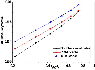
The AC losses of HTS cables with four superconducting tapes are shown in Fig. 5. The transport current has been normalized to different HTS cables. AC loss is found to be related to the transmission current, and smaller AC loss is produced by the smaller transmission current. In addition, the result also shows the TSTC cable AC loss increases an average of 40% more than other cables, and Double coaxial cable AC loss is the least. The Double coaxial cable and CORC cable exhibit shows the better performance in AC loss properties.
0.2 0.4 0.6 0.8 1
1E-5 1E-4 1E-3 0.01
A
C
l
o
ss(
J/
cycl
e/
m
)
IAC/Ic
Double coaxial cable CORC cable TSTC cable
Fig. 5. AC loss of HTS cables with four superconducting tapes.
B. The Different Background Magnetic Field
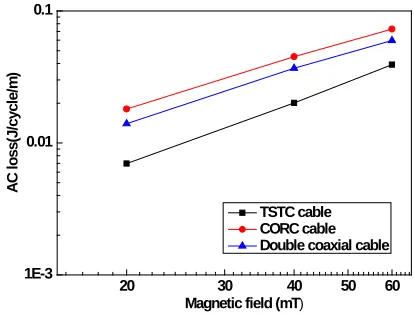
[image:3.612.305.562.80.206.2] [image:3.612.331.533.389.539.2] [image:3.612.48.296.490.600.2]J/m/cycle. Therefore the simulation value of the CORC cable with four tapes is found to be reasonable.
20 30 40 50 60
1E-3 0.01 0.1
Magnetic field (mT)
A
C
l
o
ss(
J/
cycl
e/
m
)
TSTC cable CORC cable Double coaxial cable
Fig. 6. AC loss of HTS cables with four superconducting tapes under different background magnetic fields.
C. The Different Inner Conducting Layer Pitches of Double
Coaxial Cable
The AC loss in Double coaxial cable with different inner conducting layer pitches of is shown in Fig. 7, and the transport currents of HTS cables reach 200 A. The parameters of Double coaxial cable with different inner conducting layer pitches are shown Table II, and a comparison is made between Cable A and Cable E. The result shows the Double coaxial cable AC loss is related to inner conducting layer pitches, and that smaller AC loss is produced by smaller inner conducting layer pitch when outer conducting layer pitch is the same. The smallest twist pitch of superconducting tape is 70mm according to the minimum-bending diameter in this paper. Therefore, Cable C is the proposed better design for the Double coaxial cable inner conducting layer pitch when outer conducting layer pitch is 20 mm.
TABLE II
PARAMETERS OF THE DIFFERENT INNER CONDUCTING LAYER PITCHES OF
DOUBLE COAXIAL CABLE
Items Copper Radius
Tape number
Pitch (Inner)
Pitch (Outer)
Cable A 3 mm 2 20 mm 20 mm
Cable B 3 mm 2 40 mm 20 mm
Cable C 3 mm 2 70 mm 20 mm
Cable D 3 mm 2 90 mm 20 mm
Cable E 3 mm 2 No twist 20 mm
The maximum magnetic flux density of different inner conducting layer of Double coaxial cable is shown in Table III. It is found that smaller maximum magnetic flux density of the cable is produced by smaller inner conducting layer pitch. The maximum magnetic flux density B⊥ of Cable A is 0.0154T, however that of Cable C is 0.0192T. The magnetic field generated by outer conductor layer weakens the magnetic field generated by inner conductor layer. The magnetic field direction of two superconducting tapes for Double coaxial cable is shown in Fig. 8.
TABLE III
THE MAXIMUM MAGNETIC FLUX DENSITY OF DIFFERENT INNER CONDUCTING LAYER OF DOUBLE COAXIAL CABLE
Items B⊥ B‖
Cable A 0.0154T 0.0182T Cable B 0.0185T 0.0187T Cable C 0.0192T 0.0190T
Cable A Cable B Cable C Cable D Cable E 0.00080
0.00085 0.00090 0.00095 0.00100 0.00105 0.00110 0.00115
A
C
l
o
ss(
J/
cycl
e/
m
)
Calculation Scenario
Double coaxial cable
Fig. 7. AC loss of different inner conducting layer pitches of Double coaxial cable.
Fig. 8. The magnetic field direction of two superconducting tapes for Double coaxial cable
IV. CONCLUSION
[image:4.612.54.261.96.253.2] [image:4.612.315.566.321.401.2]REFERENCES
[1] Zhang H, Zhu J, Yuan W, et al. Electromagnetic analysis of YBCO superconducting cables with high current transporting for electric devices[J]. IEEE Transactions on Applied Superconductivity, 2016, 26(7): 1-4.
[2] Takeuchi K, Amemiya N, Nakamura T, et al. Model for electromagnetic field analysis of superconducting power transmission cable comprising spiraled coated conductors[J]. Superconductor Science and Technology, 2011, 24(8): 085014.
[3] Goldacker W, Frank A, Heller R, et al. ROEBEL assembled coated conductors (RACC): Preparation, properties and progress[J]. IEEE Transactions on Applied Superconductivity, 2007, 17(2): 3398-3401. [4] Goldacker W, Grilli F, Pardo E, et al. Roebel cables from REBCO
coated conductors: a one-century-old concept for the superconductivity of the future[J]. 2014, 27(9):904-911.
[5] van der Laan D C, Lu X F, Goodrich L F. Compact GdBa2Cu3O7–δ coated conductor cables for electric power transmission and magnet applications[J]. Superconductor Science and Technology, 2011, 24(4): 042001.
[6] Takayasu M, Chiesa L, Bromberg L, et al. HTS twisted stacked-tape cable conductor[J]. Superconductor Science and Technology, 2011, 25(1): 014011.
[7] Takayasu M, Chiesa L, Minervini J V. Investigation of REBCO twisted stacked-tape cable conductor performance[C]//Journal of Physics: Conference Series. IOP Publishing, 2014, 507(2): 022040.
[8] Sheng J, Vojenčiak M, Terzioğlu R, et al. Numerical study on
magnetization characteristics of superconducting conductor on round core cables[J]. IEEE Transactions on Applied Superconductivity, 2017, 27(4): 1-5.
[9] Majoros M, Sumption M D, Collings E W, et al. Magnetization losses in superconducting YBCO conductor-on-round-core (CORC) cables[J]. Superconductor Science and Technology, 2014, 27(12): 125008. [10] Grilli F, Zermeño V M R, Takayasu M. Numerical modeling of twisted
stacked tape cables for magnet applications[J]. Physica C Superconductivity & Its Applications, 2015, 518:122-125.
[11] Philipp A. C. Kr¨ger, Victor M. R. Zermeño, Makoto Takayasu, et al. Three-Dimensional Numerical Simulations of Twisted Stacked Tape Cables[J]. IEEE Transactions on Applied Superconductivity, 2015, 25(3):1-5.
[12] Zermeño V M R, Grilli F. 3D modeling and simulation of 2G HTS stacks and coils[J]. Superconductor Science and Technology, 2014, 27(4): 044025.
[13] Zhang H, Zhang M, Yuan W. An efficient 3D finite element method model based on the T–A formulation for superconducting coated conductors[J]. Superconductor Science & Technology, 2017, 30(2):024005.