Rochester Institute of Technology
RIT Scholar Works
Theses Thesis/Dissertation Collections
8-5-2014
Parasitic Databases
Svetlin Tzolov
Follow this and additional works at:http://scholarworks.rit.edu/theses
This Thesis is brought to you for free and open access by the Thesis/Dissertation Collections at RIT Scholar Works. It has been accepted for inclusion in Theses by an authorized administrator of RIT Scholar Works. For more information, please [email protected].
Recommended Citation
Parasitic Databases
By
Svetlin Tzolov
Thesis submitted in partial fulfillment of the requirements for the
degree of Master of Science in Information Technology
Rochester Institute of Technology
B. Thomas Golisano College
of
Computing and Information Sciences
Department of Information Technology
08/05/2014
Adviser: Dianne Bills
Table of Contents
Abstract...i
Basic Premise...ii
[image:3.612.57.560.134.731.2]What is a parasitic database?...ii
Figure 1. ICMP Packet Structure...iii
Figure 2. Example Payload of ICMP Data Request Packet...iv
Figure 3. Example Payload of ICMP Data Request Reply Packet...iv
Parasitic Database Storage Overview...v
Figure 4.1: Step 1 of Information Request...vii
Figure 4.2 : Step 2 of Information Request...vii
Figure 4.3 : Step 3 of Information Request...viii
Figure 4.4 : Step 4 of Information Request...ix
Figure 4.5 : Step 5 of Information Request...ix
Figure 5 : Basic Structure (assuming only two data packets)...x
Figure 6: Packet Cycling...xi
Storage and Redundancy...xii
Figure 7: Redundancy Metrics...xiii
Figure 8: Redundancy Country Types...xiv
Figure 9: Redundancy Target Type...xv
Figure 10: Redundancy Connection Type...xvi
Who Would Use This Technology and Why?...xvii
Database Issues...xviii
Row Storage...xviii
Figure 11: Data Encryption...xviii
Figure 12: Result Example...xix
Figure 13: Simple Row Storage...xix
Figure 14: Alphanumeric Row Storage...xx
Requesting Rows/User Identification...xxi
Figure 15: Authenticator Identification...xxii
Searching...xxiii
Figure 16: Row Storage Salting...xxiv
Figure 17: Data Request Format...xxiv
Security Issues...xxv
Parasitic Database Server Security...xxv
Server and Data Security...xxvii
Figure 18: Packet Interception...xxvii
Figure 19: Packet Stream Salting...xxix
Figure 20: Row Reconstruction...xxx
Client Security...xxx
Figure 21: Algorithm Distribution...xxxi
Figure 22: Algorithm Acquisition Without Physical Media...xxxii
Practical Documentation...xxxiv
Conclusion...xxxvi
References...xxxviii
Acknowledgments
I would like to thank everyone who has helped me along the way of this thesis.
Firstly I would like to thank my adviser Dianne Bills, who has helped me every step of the way and has shown tremendous patience with my work. From helping me with developing my ideas to simply offering words of encouragement when they were needed. A wonderful scholar with a lot of truly interesting ideas and viewpoints on many fascinating topics. I truly could not have done it without you.
I would also like to thank the other members of my committee, Edward Holden and Yin Pan, both experts in their fields and wonderful professors. Their insight and multitude of different views on my works has helped me advance it much more productively.
I wish to thank all the professors that helped me through the classes that I have taken, as well as all the helpful RIT staff that has supported me throughout my study here.
Finally I would like to thank my family for all their support and encouragement through the whole process, from their concerns and words of reassurance to the constant question of when I am
Abstract
A parasitic database combines the fundamental principles of parasitic storage with those of traditional
database theory to create a distributed data storage strategy that provides basic database functionality in
a design specifically intended to ensure high data security. This approach is inspired by parasitic
network storage in which information is stored within network traffic across many machines, usually
unbeknownst to their owners, using a communication protocol such as Internet Control Message
Protocol (ICMP), etc.
The basis for parasitic data storage is that highly confidential user data is physically "stored" through
continuous packet transfer between various nodes within a network. This thesis builds upon this initial
idea and presents a possible design approach that uses standard ICMP packet architecture. Database
data rows are divided across multiple packets on multiple network nodes by splitting and distributing
them in the Data fields of ICMP packets. These database data packets can then be managed by a
Basic Premise
The goal of this capstone is to gather information on and to propose a design for storing small amounts
of highly confidential data “parasitically” on a computer network, hereafter called a “parasitic
database” data-storage strategy. This includes an investigation on how this approach could be
implemented, its benefits and usefulness, security, and some of the problems that could be faced if it is
implemented. Key to this investigation is understanding the fundamental concepts of parasitic storage
on computer networks.
The basis for parasitic data storage is that user data is physically “stored” through continuous packet
transfer between various nodes within a network. This capstone builds upon an initial design idea - as
proposed in a 2011 ACM poster session [7] - and presents a possible design approach that uses standard
ICMP packet architecture. Database data rows are divided across multiple packets on multiple network
nodes by splitting and distributing them in the Data fields of ICMP packets. These database data
packets can then be managed by a specially designed parasitic database management system with a
client- server architecture. The overall design emphasis is on maintaining both data security and data
integrity.
What is a parasitic database?
The concept of a parasitic database is built upon the idea of parasitic storage. Parasitic storage means
storing information on many machines and network nodes, usually unknown to their owners, in
network traffic through either the Internet Control Message Protocol (ICMP) [1] or possibly with
The basic idea supporting any communication between a networked client and server, including a
parasitic database server, is the “ping-pong” system of ICMP. A ping is a simple packet sent to a remote
machine that can be on a local or a remote network. Based on the RFC 792 specifications regarding
ICMP [4], the protocol was designed for troubleshooting connections and determining whether or not a
given machine, or network node, is reachable on a network. The default behavior for a computer that
receives a ping packet is to respond with a pong packet. This pong packet contains the same data that
was sent to it as a "life sign." This basic communications behavior is integral to the functionality of
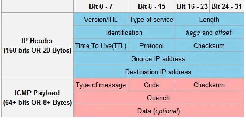
parasitic storage and by extension parasitic databases. Figure 1 shows the basic structure of the ICMP
[image:7.612.106.508.307.504.2]packets that is the basis for this investigation of parasitic databases.
Figure 1. ICMP Packet Structure
While the IP header section of the ICMP packet determines the “behind the scenes” functionality such
as where it will be sent to and who (it is saying) it is sent by (i.e. the Source and Destination IP
addresses) or the time to live (TTL) which determines through how many machines a packet can be
routed, the important areas for this project are in the Payload section. This part of the packet contains
out with an ICMP are returned when the target machine responds, thus allowing for parasitic storage
during the time that the packet is traveling.
Below is an example of a request for data from a client along with the reply containing the data from
the server. Both messages include “salt” which is random bits of data that are inserted into passwords
and other strings of data in order to make them more resistant to sniffing and other types of attacks.[5]
Type = 8 (Echo Reply Request) Code = 0 (No codes for
Echo request)
Checksum = CALCULATED
Data = Username;Salt;Password;Salt;Identifier-of-Requested-Data;Salt
Encryption Key 1, Encryption Key 2
Figure 2. Example Payload of ICMP Data Request Packet
In this example, the entire ICMP Data portion of the payload is transmitted as ciphertext. The distinct
portions of the data (Username, Password and Identifier-of-Requested-Data) could be encoded with
multiple separate keys in order to have layered protection in case there is a security leak and a key
becomes known to unauthorized personnel.
Type = 0 (Echo Reply) Code = 0 (No codes for
Echo request)
Checksum = CALCULATED
Data = ServerID;Salt;Data;Salt
Encryption Key 1, Encryption Key 2
Just like in the previous example, the ICMP Data field of the packet is used to send the database data
back to the requesting machine while still maintaining security through the use of salt and encryption.
This functionality is explained in more detail in the Database Issues section of this document.
Parasitic Database Storage Overview
The fundamental goals of a parasitic database are to provide the basic functionality of a traditional
RDBMS and to follow important principles such as ACID where possible, while providing several
extra layers of security in the form of data distribution over many nodes, encryption, salt as well as an
authentication system that can be tailored to various different deployment possibilities.
To accomplish the goals of parasitic databases, the Data field in the payload of ICMP packets is filled
with the database data that needs to be stored and that will be sent to a target machine. Once it reaches
the target machine, the packet with the payload is returned either immediately (ICMP) or after a
specified time (SMTP). This data is then sent out to another machine, without retaining it on the host.
Essentially this creates a constant up/down “stream” or flow of data that is never stored on the local
host but is instead continually cycled between the host and the external machines. Some of the benefits
of using a parasitic database include increased data security due to the nature of parasitic storage as
well as plausible deniability1 due to the setup of data transfer.
Using this approach for data storage requires that both the user data and the database metadata be
organized and stored so that external users can be authenticated or otherwise authorized, specific data
can be requested by these users, and typical data modification activities are supported - all without
interference or loss of security. This type of datastore can reside on a network with no, or only very
short-lived, storage making this design ideal for handling sensitive information.
The principles for this are similar to the basis behind the authentication methods used in high security
systems. An example would be the authenticators that are used for remote, and sometimes even local,
connections to high-security systems. The passwords that these devices periodically create exist for a
very short time frame and are only valid until the next one is automatically generated. This makes
acquiring one by illegitimate ways very difficult since the information is only valid for a very short
time, much like the idea behind the packet system of the parasitic database. [6]
Simply stopping the Parasitic Database Server would destroy all of the database data without a trace,
since all packets stored under this strategy are transiently kept in memory as well as in the network
stream and would be lost when the machine loses power.
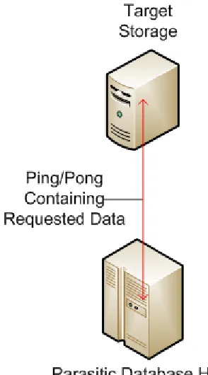
A request for information could be handled as follows. Please note that the following diagrams are
Figure 4.1: Step 1 of Information Request
This diagram displays the first step of the information request process. A single packet containing some
data is being “bounced” back and forth with ICMP messages between the parasitic data host and a
storage machine somewhere in cyberspace.
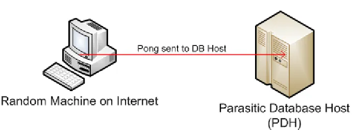
[image:11.612.133.477.522.608.2]The second step of the request process is that the Information Requester sends a PING request to a
random machine using a “spoofing” process. This means that the ICMP packet sent will contain the IP
of the Parasitic Database Host in the header as the “Source IP,” rather than the IP of the machine that
truly sent it, namely the Information Requester. The ICMP Data field will contain the requested
information ID or other identifier, as well as the real IP of the Requester, so that once the packet is
received by the Parasitic Database Host it will know how to structure the return packet. This means that
[image:12.612.134.480.296.430.2]the random machine that is chosen is being used as a proxy.
Figure 4.3 : Step 3 of Information Request
In Step 3 of the request process the request is forwarded through a “reply process.” The previously
mentioned Random Machine forwards the request as a pong response to the Parasitic Database Host,
due to the nature of the header which contained its IP address in the source field. Thus, the random
Figure 4.4 : Step 4 of Information Request
Once the Parasitic Database Host reads the payload of the packet it will retrieve the information
requested by waiting for the data (in previously sent out packet(s)) to return; and forwards it as one or
several ping packets to another Random Machine with a spoofed IP header containing the IP of the
Requester, forcing the Random Machine to essentially forward the packet instead of replying, just like
before.
[image:13.612.122.469.545.638.2]As shown in Figure 4.5, the Random Machine then “replies” to the ping of the Parasitic Database Host
and forwards the Pong to the Requester which then decodes the information in the payload of the
packet in the same way that the initial request was handled. During this entire exchange no direct
contact has been established between the Parasitic Database Host and the Information Requester at any
point in time. As previously mentioned, this provides plausible deniability in external networks and an
added layer of security in internal ones.
Figure 5 displays the basic structure of the “storage” technique that can be used when designing a
parasitic database, as well as a simple explanation of how redundancy could work. Again, transmission
[image:14.612.155.478.349.660.2]complexity is simplified by assuming only two data packets.
The data would be read from an external source which is disconnected after all data has been read. The
separate data payloads are then sent out to Machines 1 and 3 on the network. The Parasitic Database
Host or PDH, which functions as a packet injector, calculates (as explained in the Storage and
Redundancy section) while sending out the packets that they need only one redundant backup each and
sends these copies to Machine 2 and 4. This means that there are now two copies of each packet
[image:15.612.125.484.237.593.2]circulating throughout the network.
Figure 6 deals with the cycling mechanics of the database, which are used to prevent the data packets
from being noticed by the external machines (otherwise they could appear to be a DOS attack or at
least a PING probe) or from being predictable and vulnerable to sniffing or other types of detection. To
accomplish this, the packets cycle through many machines in a predetermined order that enables the
parasitic database host to avoid arousing unnecessary suspicion. In the above example we assume one
packet and a cycling count of four. The initial payload is sent to External Machine 1. Once the pong is
received the data is then sent out again to External Machine 2 with the same process repeating for all
four machines. Once the fourth machine replies, the cycle starts anew at Machine 1. This should
provide a good balance between detection prevention and using too many different external machines
which could cause unnecessary overhead.
Storage and Redundancy
Redundancy is a key property for any type of database, be it in the form of backups, mirror sites or
other methods of ensuring that no data is ever lost. Due to the nature of this database and the fact that
security is a critical issue, backups cannot be made in the same way as traditional databases. Thus
there needs to be a different type of redundancy to make sure that there is no data loss, even if a data
node holding a given packet goes down. To ensure this, the server must send out multiple copies of
each packet in order to ensure that a copy of a given data item is always available. An easy way to do
this is to have a set number of redundant packets. However this simplistic approach could either result
in too much redundancy, and thus cause pointless bandwidth use, or too little redundancy, risking data
loss. A better way to balance bandwidth use and achieve the level of redundancy necessary to avoid
data loss is to calculate the required number of redundant packets on the fly depending on a number of
Metric Symbol Type or Units
Bandwidth B Bytes/second
Bandwidth Used BU Percentage (%)
Server Location Country Type C Category (see Figure 8) Target Location Country Type CT Category (see Figure 8)
Target Type T Commercial/Residential
Connection Type CT DSL/Dialup/Satellite/Cable
[image:17.612.56.555.54.213.2]Number of Data Chunks D Integer
Figure 7: Redundancy Metrics
There has been some research done on redundancy for parasitic storage [1][2], but not for the specific
scenario of a parasitic database. Other formulas and calculations for this handle this issue differently.
Some assume multiple senders and receivers as well as an at least a somewhat controlled environment,
meaning that variables such as line noise are important. The difference between these calculations and
what is required for the parasitic database is that the parasitic database will host small amounts of data
in various different locations in the world and it concentrates more on security, authentication and
sending discrete amounts of information through proxy machines rather than on raw throughput. It is
important for a database like this to remain “off the radar” by not being too active; so the total amount
of data that this type of database can store is dependent on how “hidden” it needs to be. Limiting its
throughput and therefore storage capability has to be balanced to allow for the data lookups and other
requests that a database must handle.[2] Because this kind of database could be deployed in various
locations in the world, it lends itself to providing a secure information exchange service in the field for
various types of organizations and corporations. Because of this potentially broad area of deployment,
it is important to have a redundancy formula that takes into account the capabilities of the available
deployed in both underdeveloped countries as well as in the internal networks of sophisticated
organizations. Because security and not throughput is the main concern of a parasitic database, the
calculations below concentrate more on the overarching performance measurements rather than on
line-specific details.
In order to allow extra, non-database related commands to be run, such as IP lookups for countries, as
well as to account for network issues, roughly 65-70% of the total bandwidth could be used to run the
database. This should ensure that data loss is highly unlikely and that the connection does not arouse
suspicion by being at peak use at all times due to the noise that can be created using the extra
bandwidth. In cases where secrecy is of greater importance, much less of the bandwidth should be
used, say about 10-20%. In such cases the data is generally much smaller and more compact as well,
which lends itself well to this approach. In order to prevent suspicion the rest of the bandwidth can be
used to simulate regular Internet use with highs and lows according to the hour of day. These are just
rough estimates, however; and more precise measurements should be done as the investigation of this
topic progresses.
The country in which transmission occurs is also important for this type of implementation and it can
be summarized as follows:
Type Examples Factor
Highly Developed Networks USA, Canada, Germany, France etc. 2
Medium Developed Networks Serbia, Kosovo etc. 3
[image:18.612.52.554.553.632.2]Underdeveloped Networks Iraq, Ghana, Bhutan etc. 4
These categories would each provide a factor for the formula to ensure that packets do not get lost due
to connection problems both within the countries from which they are being sent or the countries to
which they are beings sent.
Pinging a payload to a commercial machine such as a commercial website server or an internal
company server would have a greater potential of “staying alive” than using a residential machine
which might be turned off, disconnected, or change its IP address at any time. This means that a packet
going out to a commercial machine needs less redundancy in order to ensure no loss of data than a
packet sent to a residential one.
Type Examples Factor
Commercial www.google.com, in-house server 2
[image:19.612.59.554.331.392.2]Residential Any personal machine 4
Figure 9: Redundancy Target Type
The different connection types available are shown in Figure 10. It is important to note that some are
more prone to connection problems than others. Anything sent through a cabled connection has a lesser
chance of being lost when compared to satellite. Both of these are also much less likely to lose any
Type Factor
Cable 1
Satellite 2
DSL 1
[image:20.612.67.552.54.156.2]Dial-up 4
Figure 10: Redundancy Connection Type
A sample calculation, according to the metrics in Figure 7, of how much redundancy is needed could
look like this:
Calculation Formula Explanation
Total number of packets
that can be sent
((B*(BU/100))/70) ((Total Bandwidth*(Percent of
Bandwidth to be
used/100))/size of ping packet)
Total Number of Packets
that need to be circulating
for appropriate data
redundancy
D*(C+CT+T+TC) Number of packets*(Country
Type Server + Country Type
Target + Target Type +
Connection Type)
If the number of packets from calculation #1 > calculation #2 then this implementation can work as this
means that there is enough possible bandwidth to accommodate it in a given location. The total packet
Who Would Use This Technology and Why?
When using the ICMP protocol, this technology allows relatively small amounts of data to be stored in
a parasitic manner: roughly 7.3GB on a 2Mbps connection and up to 365GB or more on a 100Mbps
line, as calculated by Michal Zalewski in “Silence on the Wire” [3]. However neither of these numbers
factors in any of the extra functions and additions to the parasitic model that are required to support a
database architecture such as redundancy and obfuscating traffic.
This data storage strategy could be beneficial to a variety of organizations where data security is key.
On the high end, highly competitive research and development companies could decide to keep
strategic and key information on new prototypes, experiments or discoveries in a parasitic database
within their own internal network. This would add security should their external security measures be
breached, since an attacker would first have to determine that such a database strategy is in use and
then manage to sniff and decrypt coherent messages from the network traffic. Ideally, before the time
that this could occur, a company with appropriate network security would have noticed the breach and
would be acting upon it.
On the other end of the spectrum, this type of database can be used by private and federal organizations
that handle sensitive operations where access to information needs to be discrete and very hard to trace.
This could provide security in undercover operations for example, where agents would be under
surveillance. Authenticating and accessing data in this type of database would be nearly impossible to
identify and trace unless somebody knew exactly what to look for, and even then would be very hard
Database Issues
There are many different features that make up a database; however for this implementation only the
basics will be considered. These include handling the relational table architecture as well as the DML
commands that are used to enter, edit and delete data. To implement these functions the database and
the clients will have to use techniques such as IP spoofing and packet header modification in order to
re-direct packets as required.
Row Storage
Storing the row data comes in two parts: pre-seed and post-seed. For pre seed, the rows are stored in an
unencrypted format, fed through an encryption/salting program (Figures 11, 12) then seeded into the
[image:22.612.216.396.373.641.2]network to which the server is currently connected.
Figure 12: Result Example
Once the data is seeded, it is stored on the server in a way that allows for its retrieval and transmission
should it be requested by a client. This involves using a simple indexing system as well as adding
identifiers for the start of each row, in order to allow the reconstruction of the row by the client as
required and as explained in the Security section of this document. See the Figure 13 for an example of
how a seeded row would look when stored on the database server.
Primary Key Row Packets
[image:23.612.60.556.58.131.2]1 142;421;531;23;551;203;124;125;5094
Figure 13: Simple Row Storage
Each row that is stored on the server follows this pattern. Each has a primary key as a unique identifier.
This is used when rows are requested, in order to retrieve the required packets and resend them. For
simplicity, this identifier can be either a system-generated, non-data pseudo-key (such as a numerically
increasing integer - although it does not allow for any true searching) or some type of alphanumeric
identifier that represents at least some part of the data that is required for searching such as dates,
Encrypted Data
Part 1 Part 2 Bogus Data(Salt) Part 3
Bogus Data (Salt)
Bogus Data
(Salt) Part 4 Part 5
names etc. The row packet stream simply states the IDs of packets that belong to this row in no specific
order aside from the first one, as it denotes the first packet of the row in order to allow the client know
when it receives it where to begin.
The primary key can be coded in various ways to increase security and to only allow certain people to
understand and use it for searching the database, as show in the example below.
Primary Key Row Packets
[image:24.612.54.553.249.326.2]3A1930 142;421;531;23;551;203;124;125;5094
Figure 14: Alphanumeric Row Storage
For example this sort of primary key could denote data from 3rd August 1930 or Room 3A in building
19 on floor 30. Using this sort of system supports versatility while not completely compromising
security. It does, however, limit the data somewhat since the primary key always needs to be unique
which is data dependent. This can be impossible for some types of data, and composite keys are more
difficult to implement. Composite keys would also lower data security since such a key would reveal
more about the data than would a unary key. Using anything other than a pure numeric primary key
lowers security in situations in which the server is compromised however it allows for (better)
searching and thus is a decision that must be weighed based on the specific goals of the system to be
implemented.
The row packet identifiers (IDs) are encrypted and stored in the Data portion of the ICMP packet along
with the data. The IDs for each packet are provided during the encryption process and are encrypted
Some of the IDs belong to bogus data packets inserted solely for noise; however the server does not
differentiate them and it is up to the client to be able to filter out the unnecessary data, as explained in
the Security section of this document. The packets are listed in a random order in the packet ID string,
not in the order that the IDs were given, in order to increase security. The only ID that has a given order
is the first one, since it is important to denote which packet begins a row without any identification for
the end of the row or the order of the packets. This allows for the reconstruction of the row when
received by the client while still providing sufficient security for the data.
Requesting Rows/User Identification
Requesting rows from the server follows the basic method shown in Fig. 4.1 - 4.5 which is designed to
maintain security. Requesting rows from the server is only possible by requesting certain rows by
primary key which was described in the previous section.
To increase data control, a simple username/password system could be implemented in order to add
another layer of security. Such an implementation would look something like what is shown in Figure
2. This would allow only registered users to make use of the system which could be useful on closed
networks such as internal corporate networks; however it opens up another set of data that can be
compromised should the server be successfully attacked. This makes it slightly less useful for using this
system on open networks such as the Internet. It does, however, allow different users to have different
sets of permissions in order to access restricted portions of the data.
A possible authentication system that can be used on an open network is something that uses a timed
identification token such as a RSA dongle or other approach that provides an algorithm-based
traffic or identification, completely while still allowing only authorized clients from accessing the data.
The following could be an example of this setup.
Type = 8 (Echo Reply Request) Code = 0 (No codes for
Echo request)
Checksum =
CALCULATED Data = Salt;Authenticator Token;Salt;Identifier of requested data;Salt
Figure 15: Authenticator Identification
This setup is not impervious to a security breach however. If an attacker can compromise the
authentication and salting algorithm it would be possible to request any data from the server. Even if
they could not make use of it, this would be a security issue since it violates the rule of least privilege.
However it does more to protect individual users from being identified in case of a breach since there
would be no way to identify individual users when using the same authentication algorithm.
There is a middle ground between these two options, however. It would also be possible to split data
access into roles, as is done in many RDBMS such as Oracle, each having a separate authentication
algorithm that would allow the database to still implement the rule of least privilege while not
identifying individual users outright.
Similar to the primary key issue, the way that the authentication is done depends entirely on how and
Searching
While security is undoubtedly an important part of the parasitic database, so is the basic database
functionality that is necessary for a system of this type to function. While many of the more complex
database functions that many take for granted in commercial databases are undoubtedly useful, they are
less feasible when dealing with the security measures put in place in this design. Functions such as
multiple row retrieval and advanced searching using multiple WHERE clauses, for example, are very
hard to implement in the current design since they require the server to have direct access to the data.
Giving the server access to the data is too big of a security risk for the functionality to compensate.
This database has not been designed to handle small databases containing simple, sensitive data that
does not require a lot of filtering to use.
The middle-ground solution for this limitation, however, would include some of the data, perhaps even
metadata, in the primary key to allow it to be searched like a string. Various parts of the key string can
represent different pieces of information as shown in the Row Storage section of this document. This
would be the only way that searching could be feasible in the current setup; however it means that the
primary keys would need to be salted at the very least in order to prevent data leaks in the case of a
security breach. If we take the example we used in that section the salted result could look something
like the following.
Original
Primary Key Row Packets
Salted
Primary Key Row Packets
3214DGQWA1412QS9332FS0OIS 142;421;531;23;551;203;124;125;5094
Figure 16: Row Storage Salting
As shown in Figure 16, the data needed for a search is still there but would be much harder to decipher
should it be accessed by someone without authorization. Now to enable searching, all primary keys
would need to follow the same formula for construction as well as use the same salting algorithm and
be the same length. The server would need to have access to the salting algorithm in order to be able to
do searches on the primary key which is a security issue; however for some implementations it would
be better to allow the server access to it rather than not having it depending on the deployment location
of the server.
Searching could be implemented by allowing simple clauses to be sent to the server such as the
following.
Type = 8 (Echo Reply Request) Code = 0 (No codes for
Echo request)
Checksum =
CALCULATED Data = Salt;Authenticator Token;Salt;RWHYG1900;Salt
Assuming the primary key for this row included the year 1930, this request could mean Request WHere
Year Greater than 1900. This is a simple example, however, and it can be enhanced with salting the
request format itself to increase security. This would require a basic database interpretation engine to
either be obtained or more likely written for this purpose, in order to include the various salting
algorithms. Considering that the clauses that can effectively be used in this setup are limited, a full
engine would not be required.
Security Issues
Security is always an issue when it comes to data and information storage, and it is no different here.
However, several additional threats are present along with the common ones that target databases.
Local security relating to securing the physical machine that is running the parasitic database will be
briefly discussed but not focused upon.
Parasitic Database Server Security
In order to start the flow of information into the parasitic database, the server must at some point have
access to data in raw form. This is a large security concern because the data that is to be sent out would
generally be sensitive and a compromise here would be catastrophic. To improve security, the database
data to be sent would be pre-encrypted on an external machine with no network connectivity in order to
prevent any network-related security concerns and to maintain the ability to strictly control physical
access to the machine. The encoding process would include the introduction of salt and white noise to
the data. The database data would then be split up into files containing packet-sized payloads and
and ultimately sent out is useless without the decryption key as well as knowledge of the algorithm that
determines the sequence of valid packets.
This data is then stored on an external storage device that will be used to transfer the data onto the
server. The server will sequentially read each file with the encoded data and send it out into the
network, setting up redundancy as it goes. Once all the data is read and sent into the network, the
external storage will be removed to increase security. The data would now exist solely on the network
as payloads. The actual server does not store any of the data at any time and does not have access to
any of the encryption/decryption keys. This means that even a physical compromise of the system
would not cause a sure loss of data. The server also has no access to the salt algorithm which means
that it has no way of distinguishing the real data packets from the fake ones. It simply replies to any
requests by retrieving the needed packets and simply forwarding the payload.
As displayed in Figure 7, the unencrypted data file, which is read from an external medium, is sent
through an encryption program that encrypts it as well as splitting it up into packet-sized files and
introducing salt as shown in Figure 8. By providing pre-split chunks of data we eliminate or at least
vastly limit the need for packet fragmentation which would cause unnecessary overhead as well as
possibly arouse suspicion if the packets that are sent out are too large.
Figure 12 shows an example of the result of the encryption process described in Figure 11. The base
data, once read, will be encrypted, split and then injected with bogus data as false packets according to
an algorithm. Only those parties that possess the correct algorithm to filter out the salt will be able to
read the real data. This helps ensure the security of the data and increase resistance to sniffing attacks
This figure shows a simplified setup of a row of data being split into four packets, each sent to a
different external machine. Packet 3 is intercepted either by a malicious hop in the routing that the
packet takes or at the external machine itself, since there is no real way to know what machine the
packets are being sent to outside of obvious IP ranges such as corporate or government controlled
servers that are likely to have packet scanning firewalls installed. Whatever the case may be, Packet 3
is now compromised. On its own, however, it is completely useless, since it will contain only part of
the encrypted data as well as salt. Thus it only has a "worth" similar to a portion of an encrypted .zip or
.rar file which are functionally "corrupt" and unusable until the entire archive is assembled.
Even if three quarters of the packets in this example were intercepted the same measures would prevent
access to the data. If all four of the packets are compromised, which means that there are other security
issues present, this database setup prevents full access in several other ways. First, there is no way that
an attacker will know exactly how many packets are used to transmit a row of data. While the packets
are numbered in a way that allows them to be ordered after receiving them, there is no termination
character that denotes the end of a row as a security measure. Rows that are requested from the
database are known to be complete only when received, ordered, desalted and decrypted, since openly
designating where rows begin and end would be a security flaw in this setup.
Second, an attacker would not know how to order any of the packets intercepted unless he is privy to
the numbering system used. If an attacker knows the system used for this database setup then there are
internal security issues that need to be addressed since this information is not available on the actual
parasitic database host - again as a security measure to prevent information being accessed if it is
compromised. This information is only available to the client. An unauthorized person having this
Third, if the previous security measures have failed and the data has been intercepted and properly
ordered, the attacker would still need to filter out the bogus packets, since each row is salted not only
[image:33.612.137.477.168.263.2]within the data, but with additional salt-packets within the packet stream as well (see Fig. 19).
Figure 19: Packet Stream Salting
As shown in this example, a single row of data would be sent out as twelve packets, four of which are
filled with completely bogus data, yet are still sent when a row is requested. This is to strengthen the
resistance of the database to unauthorized access even if a full row of data is somehow intercepted.
Once the whole row is received, the client application must filter out the bogus packets before
decrypting or the resulting data will be corrupt, even though it does contain the row data somewhere.
To do this properly the client requires a separate algorithm to know which packets to filter out. This
information is stored separately from the actual application.
Fourth, if all previous security measures have failed, which means a catastrophic breach in security,
there is one final security measure in place to help prevent access to the data which is the actual data
encryption and salt algorithms. These allow the received, assembled, filtered data row to actually be
decrypted into usable data. They are again stored separately in order to prevent total security failure
Figure 20: Row Reconstruction
Client Security
Keeping the server (and the data that flows from it) secure is very important since it is a single point of
failure should proper security measures not be taken. However, it is also vital to secure the client since
it contains information that could annul all other security measures if handled incorrectly.
As discussed previously the client has access to the following system components that each require
security measures:
IP of the parasitic database host
Bogus packet pruning algorithm
Salt algorithm
Encryption algorithm
Due to the amount of information that the client requires in order to function, it is vital to protect these
separate components in a way that makes sense for the specific setup that is used. The easiest way to
provide security is to store each of the items noted above in a separate physical medium, such as USB
Part 1 Part 2 Bogus Data(Salt) Part 3 Bogus Data
(Salt)
Bogus Data
(Salt) Part 4 Part 5
Encrypted and Salted Row Part 1 Encrypted RowPart 2 Part 3 Part 4 Part 5
Row of Data Salt
parasitic database host. The reply will be in the standard ping format; however there are some changes.
The first request will garner a response containing the salt algorithm. This will be unencrypted and will
not contain bogus packets, but since it is only one design component this is a necessary risk in order to
accomplish a functional client. The next request will be for the bogus-packet pruning algorithm, which
will be returned salted but unencrypted and, obviously, without bogus packets. The final request will be
for the encryption algorithm which will be returned salted and filled with bogus packets. After all
algorithm components have been acquired the client can begin operating. This process would need to
be repeated each time the computer/client is restarted which can also be a possible security issue.
However it is a risk that is necessary in order to avoid physical media.
This setup is not completely vulnerable before it receives the various algorithms, however. This is
because the client still uses the communication system detailed in Figure 4.2 and Figure 4.3. This
design allows the requests to have at least some basic security in that there is never any direct
communication between the client and the parasitic database host, whether for requesting the various
algorithms or the data itself. This combined with the constant network traffic load that an average
computer generates, along with that from other machines on the same line as well as any additional
noise created on purpose for the sake of obfuscation would make it more difficult to trace any specific
Practical Documentation
For this thesis, the practical implementation addresses the foundation functionality of the parasitic
database approach proposed with the sole purpose of presenting the basic services of data storage: data
packet cycling along with request formation and handling by both the database client and server.
Multithreading is a necessity for even a basic implementation since the server's listener must continue
to function while other functions (such as sending replies) are running or else data cycling and client
requests could be lost. Multiple instances of other functions, such as handling multiple requests, can
only be used when multithreading is available.
In order to be able to send data requests from the client to the server, as well as the requested data
packets back to the client, IP addresses need to be spoofed. This can be done using a third machine as a
middleman in order not to have a direct connection between the client and the server. To do this
network packets need to be constructed from the lowest network layer, i.e. the physical layer, in order
to select the NIC that will be used to send the packets, Ethernet and finally the IP where the actual
spoofed IPs were introduced to the packet. The ICMP packet is then formed by combining all the
necessary layers along with the payload (i.e. data) that it will contain. (See Appendix 1)
The server application consists of one listener that is set to listen for both client data requests and the
data packets it sends itself for the storage cycling process. For the purposes of this capstone there are
only two data packets, each storing one row of user data, both of which are hardcoded into the
application. Full database functionality is left for later implementation. While cycling these packets via
packet or shows an error message should a non-existent packet be requested.
The client application consists of a listener and the functionality necessary to request one data packet at
a time. Once the data packet is received it is simply displayed. Again, full client functionality is beyond
the scope of this capstone effort.
While this is a very simplistic demonstration of how the foundation communications of the proposed
parasitic database system could work, a true implementation would include several other, mostly
security, functions as well as full DMBS functionality. The data that is stored in the packets would
never be hardcoded but rather encrypted using an external application then read into the server from a
removable external storage device. The data itself would be fragmented across multiple packets as well
as salted and sent in a random order. This however is not needed to demonstrate the basic parasitic
data-handling functionality, and has been omitted in this initial implementation.
Several attempts to create this applications were made, in several different programming languages.
Initially the plan was to create it in Java. However to create an application like this requires very low
level access to system calls in order to craft the ICMP packets used, and Java does not provide such
native functionality. The next language tried was C, which while having all the necessary capabilities,
proved to be unnecessarily complex, especially the code needed for some parts of the packet crafting
process such as the checksum calculations. Doing multithreading in C is also rather arduous to
implement. Thus the final application was written in C# using SharpPCap and PcapDotNet libraries2
that allowed for access to the lower levels of the network protocol stack and enabled the creation of
Conclusion
This thesis proposes the use of parasitic network storage for user data storage and outlines one possible
way to design and implement a parasitic database along with its basic functionality, with emphasis on
security and implementation details. The goal of this data storage strategy is to provide a secure
database platform for small sets of private or sensitive data that needs to be secured against network or
physical intrusion.
The concept of data packet cycling was developed as well as methods to ensure sufficient packet
redundancy so that user data is not lost. The communication approach using spoofed IP addresses - to
help ensure anonymity by using a random computer on the Internet as a relay - was proposed since
regular parasitic storage includes direct communication. Methods to help maintain data security such as
encryption, salt and specific distribution methods for the data were also discussed, as well as basic
database functionality such as querying, inserting and deleting rows.
A full implementation of the current design would include an encryption program to encrypt, salt, and
prepare the packets which would be fed into the server for storage via packet cycling. Appropriate
algorithms need to be identified or created for this. A proper implementation of the redundancy formula
is also needed in order to prevent data loss. Furthermore, many of the traditional database capabilities
are needed, such as functionality for inserting, deleting and updating rows as well as addressing the
issue of data indexing to support data searches and maintenance.
types such as SMTP or VoIP or even completely different network-based deployment systems. A more
in-depth and network-sensitive design of the database functionality (indexing, inserting/deleting rows,
References
[1] K. Rosenfeld, H. Sencar, N. Memon, "Volleystore: A Parasitic Storage Framework," June 2007,
http://isis.poly.edu/~parastore/volleystore.pdf. [Accessed 03/12/2010]
[2] J. Chen, J. Zhou, G. Zhou, "Characteristics analysis of parasitic storage, "Frontiers of Optoelectronics in China, Vol. 3, no. 2, 09/17/2009.
[3] M. Zalewski, Silence on the wire: A Field Guide to Passive Reconnaissance and Indirect Attacks, Edition of book, No Starch Press, 2005
[4] J. Postel, "DARPA Internet program protocol specification," September 1981,
http://www.ietf.org/rfc/rfc0792.txt. [Accessed 10/12/2010]
[5] C. Wille, "Storing Passwords - done right!," 1/5/2004,
http://www.aspheute.com/english/20040105.asp. [Accessed 10/12/2010]
[6] EMC Corporation, "RSA SecureID," http://www.rsa.com/node.aspx?id=1156. [Accessed 2/22/2011]