A Study of a Three-Phase Four-Wire Shunt Active
Power Filter for Harmonics Mitigation
Luis Fernando Ayala Maciel, Jos´e Luis Monroy Morales,
Juan Gabriel Marroqu´ın Pimentel
Departamento de Ingenier´ıa El´ectrica
Tecnol´ogico Nacional de M´exico / Instituto Tecnol´ogico de Morelia Morelia, Michoac´an M´exico
Email: [email protected],
jlmonroy [email protected], marro [email protected]
David Campos Gaona
Wind Energy and Control CentreUniversity of Strathclyde 99 George St, Glasglow G1 1RD, UK
Email: [email protected]
Abstract—The electrical power quality in three phase four wire systems, feeding nonlinear loads, can be improved by using active power filters (APF) in order to mitigate the total harmonic distortion. Harmonic currents and voltages produced by single phase, non-linear loads, which are connected phase to neutral in a three phase, four wire system, are third order, zero sequence harmonics. These third order, zero sequence harmonic currents, unlike positive and negative sequence harmonic currents, do not cancel but add up arithmetically at the neutral bus, and can be greater than the current of each of the phases. The danger that arises is an excessive overheating of the neutral, since there is no circuit breaker in this conductor, which limits the current, as occurs with the phase conductors. An excessive current in the neutral can also cause an excessive voltage difference between the neutral conductor and ground. This paper presents the theory and design of the control system used to mitigate harmonic problems in three-phase four-wire systems based on a split capacitor topology. Due to split capacitor topology has midpoint between the capacitors, this point can be used for the neutral return path, and thus, the entire neutral current flows through the DC bus capacitors reducing the number of switching devices. Simulation results are shown to validate the proposed procedures.
Keywords: Active Power Filter, Three Phase Four Wire Systems, Harmonic Compensation.
I. INTRODUCTION
Frequency, waveform and symmetry are some of the main electrical characteristics subject to variations in an electrical system due to changes of load, disturbances generated by certain equipment and faults mainly caused by external events, most of them human and natural. These characteristics vary at random with time, therefore, tools are needed to improve energy quality. The harmonic currents, generally produced by non-linear loads, represent one of the most relevant problems for electrical systems [1]. These harmonic currents are the source of undesirable effects for some equipment such as the overheating of transformers, electric motors and capacitors used to correct power factor, harmonics also cause voltage flickers and sometimes interfere with communication systems. Different solutions have been proposed to reduce harmonics problems, such as passive filters constructed by a proper ar-rangement of inductors and capacitors. Despite the simplicity,
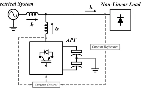
these filters suffer disadvantages of large volume, high cost and especially the susceptibility to resonances. In addition, these filters should be installed with a large capacity to compensate acceptable level of harmonics [2]. On the other hand, active filters which have been developed and are widely used to overcome the drawbacks of passive filters are a reliable option to improve energy quality. A basic scheme of a shunt active power filter when is grid-connected is shown in 1.
[image:1.612.322.565.407.562.2]The active filter purpose is to reduce principally two prob-lems; that the current flowing through the electrical system and the voltage applied to the loads remains sinusoidal. In addition to the harmonics reduction, active filters can also perform other tasks, such as the power factor correction.
Fig. 1. Basic scheme of a shunt active power filter.
In order to filter harmonics, it is necessary to have a tool allowing instantaneous active and reactive power analysis. The active, reactive and apparent power conventional definitions are based on theories developed in the 40s. These definitions have been applied successfully by electrical engineers in those scenarios where voltages and currents present a significantly sinusoidal waveform and balanced. However, the evolution of electrical power systems has required the development of new methods of instantaneous power analysis, such as the instantaneous active and reactive power theory or the p-q theory [3]. The p-q theory is an interesting method to
design control circuits and be able to inject a compensation current in the system. Also, the p-q theory advantage is the calculations simplicity, since only algebraic operations are required. Switching compensators controlled by algorithms derived from the p-q theory have been widely applied.
Voltage source inverters are an essential device to design an active filter, there are different topologies each, with its own characteristics. Three-leg split-capacitor topology use a common capacitor coupled to a dc-bus with the midpoint connected to the neutral wire, while the ac side is connected to the power supply system [4]. Due to its smaller number of legs, each of the three legs can be controlled independently.
This paper propose the design and implementation of a three-phase four-wire active power filter for current harmonic compensation in electrical distribution systems using a three-leg split-capacitor topology (TLSC).
II. P-Q THEORY INTHREE-PHASEFOUR-WIRESYSTEMS
Shunt active filters used for three-phase systems with neu-tral conductors are designed especially for neuneu-tral currents compensation (zero-sequence current components). In three-phase systems where a neutral conductor is present (as in low-voltage distribution systems), there are usually problems in transformers with a delta-star configuration, when harmonics reach the neutral of the secondary winding, they are reflected in the delta-connected primary winding causing overheating, then a fault in the transformer. Zero sequence harmonic current and voltage have a severe impact on both, the power distribution system and the devices connected to it.
The clearly knowing about the physical meaning of all instantaneous powers is an important key to develop control circuits for current or voltage compensation used in active power filters. Figure 2 summarizes the concepts involved in these powers. Three concepts are necessary to understand the physical meaning of the instantaneous powers defined in the
[image:2.612.69.284.506.572.2]αβ0 reference frame.
Fig. 2. Physical meaning of instantaneous powers.
Zero-sequence components in the fundamental voltage and current and/or in the harmonics do not contribute to the real power por the imaginary power q.
Total instantaneous energy flow per time unit (three phase instantaneous active power), even in a distorted and unbal-anced system, is always equal to the sum of the real power and the zero-sequence power (p3φ=p+p0), and may contain
average and oscillating parts.
The imaginary power q, independent of the presence of harmonic or unbalances, represents the energy quantity that
is being exchanged between the phases of the system. This means that the imaginary power does not contribute to energy transfer between the source and the load at any time [3].
Theαβ0transformation also called Clarke transformation is used to deal properly with zero-sequence voltage and current components that are separated from theαβ components, and treated as ”single phase variables” [5]. The Clarke transfor-mation and the inverse Clarke transfortransfor-mation for currents components are given by
i0 iα iβ = r 2 3 1 √ 2 1 √ 2 1 √ 2 1 −1
2 − 1 2 0 − √ 3 2 − √ 3 2 ia ib ic (1) ia ib ic = r 2 3 1 √
2 1 0
1 √ 2 − 1 2 √ 3 2 1 √ 2 − 1 2 − √ 3 2 i0 iα iβ (2)
Similarly, voltages are obtained
v0 vα vβ = r 2 3 1 √ 2 1 √ 2 1 √ 2 1 −1
2 − 1 2 0 − √ 3 2 − √ 3 2 va vb vc (3) va vb vc = r 2 3 1 √
2 1 0
1 √ 2 − 1 2 √ 3 2 1 √ 2 − 1 2 − √ 3 2 v0 vα vβ (4)
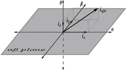
Figure 3 shows representative vector projections on a three-phase orthogonal coordinate system whose axes are calledα,
[image:2.612.329.545.508.631.2]β and0 obtained with Clarke transformation.
Fig. 3. Current vector represented inαβ0coordinates system.
conductor and currents may be unbalanced, the neutral current control is carry on using the coordinate 0.
A three-dimensional instantaneous current vector iαβ0 and
a voltage vector eαβ0 can be defined from the instantaneous
voltages and currents transformed in equation (1). Instanta-neous vectors are defined as
eαβ0= [vα vβ v0]T (5)
iαβ0= [iα iβ i0]T (6)
and instantaneous active power can be easily obtained
p=eαβ0·iαβ0=vαiα+vβiβ+v0i0 (7)
On the other hand, instantaneous reactive power is composed by a three elements vector,q0,qα andqβ, as follows
p=eαβ0×iαβ0= qα qβ q0 =
vβ v0
iβ i0
v0 vα
i0 iα
vα vβ
iα iβ
(8)
if equations (7) and (8) are combined in a matrix
p qα qβ q0 =
vα vβ v0
0 −v0 vβ
v0 −vβ 0 vα −vα 0 iα iβ i0 (9)
inverse transformation of (9) is performed as follows
iα iβ i0 = 1 v2 αβ0
vα 0 v0 −vβ
vβ −v0 0 vα
v0 vβ −vα 0
p qα qβ q0 (10) where
v2αβ0=v 2
α+v
2
β+v
2
0 (11)
From equation (10) can be easily derive active and reactive current components. Zero-sequence current i0, is divided into
a reactive part i0q and active part i0p, where i0 =i0p+i0q.
Obtained from
i0p=
v0
v2
αβ0
p (12)
i0q =
vβ
v2
αβ0
qα−
vα
v2
αβ0
qβ (13)
Similarly, instantaneous active and reactive zero-sequence cur-rents are obtained
iαp=
vα
v2
αβ0
p (14)
iαq=
v0
v2
αβ0
qβ−
vβ
v2
αβ0
q0 (15)
iβp=
vβ
v2
αβ0
p (16)
iβq=
vα
v2
αβ0
q0−
v0
v2
αβ0
qα (17)
The above equations are the base to development of control methods for shunt current compensation in three-phase four-wire systems.
III. COMPARATIVEANALYSIS OFFOUR-WIRE
COMPENSATIONTOPOLOGIES
A voltage source inverter (VSI) is used for neutral current compensation. From the currents obtained in the p-q theory, VSI generates a reverse current that is injected into the system to compensate harmonic currents. Two main topologies are used to provide neutral current compensation by voltage-source inverters; Split Capacitors Inverter and Four leg Inverter [6], [7]. Three-phase four-wire shunt active power filters mainly contain three bridge PWM converters and four bridge PWM converters, in a three bridge PWM converter neutral line is connected to the split capacitor while the four bridge PWM converter compensate neutral current using an extra bridge.
A. Split Capacitor Inverter
Split capacitor topology uses three independent controllers acting on a half bridge pulse width modulation (PWM) VSI converter. A common capacitor is coupled to a dc-bus with the midpoint connected to the neutral wire, the ac side is connected to the power supply system as shown in Figure 4 [8].
This converter, having a smaller number of legs, permits each of the three legs to be controlled independently, making the current tracking control simpler than the four-leg inverter [9]. Due to a less number of switching devices used, less number of gate drivers is needed.
B. Four-Leg Inverter
Fig. 4. Three-leg conventional converter topology ”Split Capacitor”.
Fig. 5. Four-leg inverter topology.
IV. FOUR-WIREAPF CONTROLSYSTEM
Figure 6 presents a three-phase, four-wire shunt active power filter implementation using a three-leg converter topol-ogy, in addition a instantaneous power control strategy is shown. The active power filter controller realizes a strategy to control instantaneous power, aditionally load neutral current is compensated.
The active power filter main purpose is generating harmonic currents opposite to the load harmonic currents, thus, these current above are mitigated and the total harmonic distortion is improved [10].
Control system inputs are the load phase voltages and the load line currents. The phase voltages cannot be used directly in the control because of instability problems [11]. High frequency resonance may appear near the source impedance if the measured phase voltages are used directly in the active power filter controller. To solve this problem, a low-pass filter is used with a high cutoff frequency to attenuate the harmonics at higher frequencies that contribute to the resonant effects [12].
Solving equations (1) and (3), currents and voltages are transformed to αβ0 reference frame. The αβ0 currents and voltages, are used in equation (9) to calculate the instantaneous powers, and also to achieve the system compensation. The
System A
iLb iLa
iLc
va vb vc
Non-Linear Load
iSa
iSb
iSc
iSn iLn
iFn iFc iFb iFa
Sa Sb Sc
Sa´ Sb´ Sc´ C2 LFRF
PWM Current Control
Current Reference Calculation
iFa iFb iFc vavbvc
iLb iLa
iLc
C1
Instantaneous Power Calculation
DC Voltage Regulator
Compensation Powers Calculation
vC1 vC2
i*Cb i*Ca
i*Cc
p q
pc
qc
ploss ε
Fig. 6. A three-phase, four-wire shunt active filter using split capacitor topology.
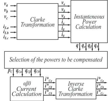
selected powers are used to calculate αβ0 compensation currents using equation (10) as shown in figure 7.
v
av
bvc
iLb
iLa
iLc
Clarke
Transformation
αβ0
Current
Calculation
vα vβ v0 iα iβ i0
Instanteneous
Power
Calculation
Selection of the powers to be compensated
qα qβ q0 q
qCα qCβ qC0 pC
i*Cα i*Cβ i*C0
Inverse
Clarke
Transformation
i*Ca
[image:4.612.50.300.242.396.2]i*Cc i*Cb
Fig. 7. Basic control algorithm based on the p-q Theory.
In [13] different compensation strategies for shunt active-filter control are discussed. To compensate unbalanced and nonlinear load using three-phase three-leg VSI topology under unbalanced voltage supply requires calculation of reference compensator currents obtained from algorithm shown in figure 7.
Dynamic hysteresis-band, which is based on PWM current control uses the generated references current to control the switch pulses of the three-leg converter [14]. Figure 8 graph-ically shows the control process of the switching devices Sa
andSa0 to generate the compensation currentiF ausing phase
aas guidei∗Sa. Thus, three half-bridge converters are working independently from each other.
Hysteresis-band current control causes voltages variation on
[image:4.612.342.527.337.510.2]Fig. 8. Hysteresis-band PWM current control in switchesSaandSa0.
average voltages of the capacitors can be caused if a dc offset occurs iniF a. A dynamic offset level is needed in both limits
of the band, this make possible the capacitor voltage difference control keep in the required levels [15].
Dynamic offsetεequation is given by
ε= k2
s∆v (18)
then
U pper hysteresis band limit=i∗Ca+ ∆(1 +ε) (19)
Lower hysteresis band limit=i∗Ca−∆(1−ε) (20)
Adding ε to the hysteresis-band limits, capacitor voltage equalization problem is solved.
V. APF SIMULATION
Using Simulink from MatLab, simulations results of the proposed filter are described in this section. As nonlinear load, a three-phase rectifier has been connected to a 400 V, 60Hz source, the filter is enabled, on 0.1 seconds. Unbalanced load current shown in figure 9 has a total harmonic distortion (THD) of 45%.
Figure 10 shows active power filter three-phase compensa-tion. Before compensation, load current and source current are the same, when active filter is enabled, compensation currents are injected to the system in order to eliminate harmonic currents. The compensated source current has a total harmonic distortion of 4.9%.
[image:5.612.50.302.47.248.2]The opposite harmonic currents injected into the system to eliminate harmonic distortion are shown in Figure 11.
[image:5.612.313.564.51.193.2]Fig. 9. Three-phase unbalanced load currentiLa,iLb eiLc.
Fig. 10. Three-phase source currentiSa,iSbeiScfiltered after 0.1 seconds.
Fig. 11. Three-phase compensation currentsiF a,iF beiF c.
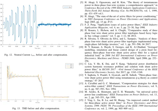
Figure 12 shows how neutral current is compensated. On the other hand, Figure 13 describes the behavior of the total harmonic distortion.
VI. CONCLUSIONS
[image:5.612.316.560.409.549.2]Three-Fig. 12. Neutral Currentisn, before and after compensation.
Fig. 13. THD before and after compensation.
leg split capacitor topology is used, the control strategy do not require a complex modulation as vector pulse width modula-tion. Dynamic hysteresis PWM current controller, controls the gates of the switching devices to generate an opposite signal taking as reference the signal extracted with the p-q theory.
Active power filter are a reliable option to compensate harmonics, passive filters contruction is simpler but they only can eliminate an harmonics range. On the other hand, active filters are capable of compensating most of the harmonic frequencies.
REFERENCES
[1] M. Rashid, Power Electronics: Circuits, Devices, and Applications. Pearson, 2009. [Online]. Available: https://books.google.com.mx/books?id=-WqvjxMXClAC
[2] M. S. Karbasforooshan and M. Monfared, “Design and implementation of a single-phase shunt active power filter based on pq theory for current harmonic compensation in electric distribution networks,” in IECON 2017 - 43rd Annual Conference of the IEEE Industrial Electronics Society, Oct 2017, pp. 6389–6394.
[3] H. Akagi, E. H. Watanabe, and M. Aredes, The Instantaneous Power Theory. Wiley-IEEE Press, 2017, pp. 472–. [Online]. Available: https://ieeexplore.ieee.org/xpl/articleDetails.jsp?arnumber=7887006 [4] T. Benslimane, K. Aliouane, and B. Chetate, “Voltage and current
disturbances elimination with reactive power compensation using unified power quality conditioner,” inInternational Symposium on Power Elec-tronics, Electrical Drives, Automation and Motion, 2006. SPEEDAM 2006., May 2006, pp. 780–784.
[5] H. Akagi, S. Ogasawara, and H. Kim, “The theory of instantaneous power in three-phase four-wire systems: a comprehensive approach,” in Conference Record of the 1999 IEEE Industry Applications Conference. Thirty-Forth IAS Annual Meeting (Cat. No.99CH36370), vol. 1, 1999, pp. 431–439 vol.1.
[6] H. Akagi, “The state-of-the-art of active filters for power conditioning,” in2005 European Conference on Power Electronics and Applications, Sept 2005, pp. 15 pp.–P.15.
[7] F. Z. Peng, “Application issues of active power filters,”IEEE Industry Applications Magazine, vol. 4, no. 5, pp. 21–30, Sep 1998.
[8] H. Kouara, L. Hichem, and A. Chaghi, “Comparative study of three phase four wire shunt active power filter topologies based fuzzy logic dc bus voltage control,” vol. 5, pp. 1–12, 06 2014.
[9] R. Silveira, S. Oliveira da Silva, and L. Sampaio, “Analysis of three-phase four-wire shunt active power filter topologies implemented using single-phase full-bridge inverters,” vol. 1, pp. 591–596, 04 2017. [10] H. Y. Kanaan, A. Hayek, S. Georges, and K. A1-Haddad, “Averaged
modelling, simulation and linear control design of a pwm fixed fre-quency three-phase four-wire shunt active power filter for a typical industrial load,” in 2006 3rd IET International Conference on Power Electronics, Machines and Drives - PEMD 2006, April 2006, pp. 252– 256.
[11] C. Liu, Y. He, K. Dai, and Y. Kang, “Industrial power distribution system harmonic resonance problem and solution with shunt active power filter,” inIECON 2017 - 43rd Annual Conference of the IEEE Industrial Electronics Society, Oct 2017, pp. 1243–1248.
[12] T. Sapkota, S. Poudel, S. Gyawali, and R. Subedi, “Three-phase four-wire shunt active power filter using instantaneous p-q theory as control strategy,” 07 2015.
[13] A. Cavallini and G. C. Montanari, “Compensation strategies for shunt active-filter control,”IEEE Transactions on Power Electronics, vol. 9, no. 6, pp. 587–593, Nov 1994.
[14] M. Aredes, K. Heumann, and E. H. Watanabe, “An universal active power line conditioner,”IEEE Transactions on Power Delivery, vol. 13, no. 2, pp. 545–551, Apr 1998.