Coupling CFD-DEM with dynamic meshing: A new approach for
fl
uid-structure interaction in particle-
fl
uid
fl
ows
Yi. He
⁎
, Andrew E. Bayly, Ali Hassanpour
School of Chemical and Process Engineering, University of Leeds, Leeds, LS2 9JT, UK
a b s t r a c t
a r t i c l e i n f o
Article history: Received 2 August 2017
Received in revised form 29 October 2017 Accepted 13 November 2017
Available online 21 November 2017
Many important engineering applications involve the interaction of free-moving objects with dispersed multi-phaseflows, however due to the challenge and complexity of modelling these systems, modelling approaches re-main very limited and very few studies have been reported. This work presents a new method capable of ad-dressing these problems. It integrates a dynamic meshing approach, used to explicitly capture theflow induced by free-moving large object(s), with a conventional CFD-DEM method to capture the behaviour of small particles in particle-fluidflow. The force and torque acting on the large object due to thefluidflow are ex-plicitly calculated by integrating pressure and viscous stress acting on the object's surface and the forces due to collisions with both the smaller particles and other structures are calculated using a soft-sphere DEM approach. The developed model has been fully implemented on the ANSYS/Fluent platform due to its efficient handling of dynamic meshing and complex and/or free-moving boundaries, thus it can be applied to a wide range of indus-trial applications. Validation tests have been carried out for two typical gas-solidfluidization cases, they show good qualitative and quantitative agreement with reported experimental literature data. The developed model was then successfully applied to gasfluidization with a large immersed tube which was eitherfixed or free-moving. The predicted interacting dynamics of the gas, particle and tube were highly complex and highlighted the value of fully resolving theflow around the large object. The results demonstrated that the capability of a con-ventional CFD-DEM approach could be enhanced to address free-bodyfluid-structure interaction problems en-countered in particle-fluid systems.
© 2017 The Authors. Published by Elsevier B.V. This is an open access article under the CC BY-NC-ND license (http:// creativecommons.org/licenses/by-nc-nd/4.0/). Keywords:
CFD-DEM Fluent Dynamic meshing Fluid-structure interaction
1. Introduction
The interaction between large objects and particle-fluidflows is commonly encountered in a wide range of applications such asfl uidiza-tion[1], chemical reactors[2–5], mineral processing, milling[6,7]and drug delivery devices[8]. The objects can have different forms, such as
fixed/free-moving internal structures or large free particles, whose size is at least one order of magnitude larger than the small particles that make up the majority of particles present. The co-existence of a large object can have an important impact on the behaviour of the par-ticulate phase, such as mixing, segregation, heat and mass transfer rate
[9]. For example, in gas-fluidized beds, immersed tubes are often used to effectively remove heat from the system and to avoid hot spots caused by chemical reaction[10,11]. In coal and wooden biomass combustion processes, large fuel particles can affect mixing and segregation behav-iour[2,3]. In some intensified chemical reactors, a free moving agitator is used for mixing and particle suspension[4,5]. In the general case of a free object, its motion is determined by both thefluidflow and its in-teraction with other particles, and conversely, theflowfield and particle
behaviour are affected by the movable object. Thus, successful model-ling of the dynamics of such a multi-scale system requires a method to solvefluid-structure interaction (FSI) problems in particle-fluidflows.
Numerical models of particle-fluidflows can be largely classified into three methods according to the treatment of the particulate and thefluid phases: Eulerian-Eulerian methods, Lagrangian-Lagrangian methods and Eulerian-Lagrangian methods [12–14]. In Eulerian-Eulerian methods, both thefluid and particulate phase are described as interpenetrating continuous phases[15,16]. Constitutive or closure relations are required to describe the solid phase pressure and viscosity. Despite its advantages in handling large-scale industrial systems as a continuum approach, these models lack the capability to access information at the particle scale due to pseudo-fluid assumption of the particulate phase. More recently, the application of Lagrangian-Lagrangian methods, such as SPH-SPH[17]and SPH-DEM coupling
[18,19], has gained popularity due to their capability in handling free-surface flows, large deformations and deformable boundaries but at a cost of high computational time. As a compromise, Eulerian-Lagrangian methods, which are normally referred as coupled CFD-DEM approaches when particle-particle collisions are resolved, are widely used. In coupled CFD-DEM, the particles are tracked individually using Newton's second law of motion while thefluidflow is determined
⁎ Corresponding author.
E-mail address:[email protected](Y. He).
https://doi.org/10.1016/j.powtec.2017.11.045
0032-5910/© 2017 The Authors. Published by Elsevier B.V. This is an open access article under the CC BY-NC-ND license (http://creativecommons.org/licenses/by-nc-nd/4.0/). Contents lists available atScienceDirect
Powder Technology
by CFD methods on a computational cell level. The forces acting on par-ticles are explicitly considered, thus a quantitative description of the particle behaviour can be obtained. To date, most CFD-DEM studies are concerned withfixed geometries, such as immersed tubes infl uid-ized systems. Different approaches have been used to treat the station-ary boundstation-ary of the tube in CFD calculation either using staircase approximation on a Cartesian grid[20,21]or accurately representing the boundary shape using body-fitted unstructured mesh[22,23]. Con-siderable efforts have been devoted to various aspects of thefluidized bed, including heat transfer[21,24,25], bubble hydrodynamics[20,26]
and erosion of the tube surface[27]. However, the capability of CFD-DEM methods to tackle FSI problems in particle-fluidflow is lacking, es-pecially when thefluidfield is described by a continuous mesh-based method, such as Finite Volume Method (FVM) or Finite Difference Method (FDM). In these cases where the free-object is represented by a single or cluster of DEM elements, the computational mesh is normally required to be larger than the dimensions of the object or the size of the largest particle present in the system to avoid the mesh being fully oc-cupied by the solid phase. Therefore, the applicability of the convention-al CFD-DEM approach is limited to particles with smconvention-all size ratio. Recently, Alobaid et al.[28]introduced an additional grid for the partic-ulate phase. The grid resolution is allowed to be smaller than the parti-cle size. More accurate predictions of the partiparti-cle motion and pressure drop are reported for thefluidized bed[28,29]. However, phase interac-tion in these methods is still modelled by drag correlainterac-tions, which inev-itably leads to a lack of detailedflow structure around the large object. Therefore, developing a new model to overcome the limitations of the conventional CFD-DEM approach in addressing FSI problem encoun-tered in particle-fluidflow is of great importance to both research and industrial practice.
Due to the presence of large free-moving object, a resolved method is necessary to obtain the inducedfluid structure. Several improvements have been proposed under the CFD-DEM framework which are poten-tially applicable to the FSI problem in particle-fluidflow. The immersed boundary method (IBM) allows the use of a rectangular grid for com-plex geometries[30]and has been applied to dispersed multiphase
flow. Takeuchi et al.[31]applied it to treat the cone surface of spouted beds, with no dynamic motion of the boundaries. Guo et al.[32] intro-duced the IBM to a CFD-DEM model and applied to several systems with moving boundaries including a study of segregation in a vertically vibrated bed, however, no systems with free-body motion were report-ed. The only work on free-body motion in these multi-phase systems is reported by Tsuji et al.[33]who represent the large object using small
fictitious spheres using an idea similar to the volume penalization meth-od. The solidity of immersed object is approximated by means of perme-ability controlled by input parameters offictitious particle diameter and solid volume fraction inside the object. Although theflow at the bodies boundary is not fully resolved, experimental validation showed good agreements on the position of a free-moving large sphere during and after stopping thefluidization[33,34]. Its applicability for more complex geometries is not clear, and additional computational costs will be re-quired for complex geometries in order to identify those computational cells containing the solid structure. Moreover, it is worth noting that the above models may face challenges in the resolution of boundary layers in turbulentflows.
With increasing demand on engineering applications, coupling DEM with versatile commercial or open source CFD software, for instance, Fluent, CFX, OpenFOAM and MFIX, among many others, is gaining pop-ularity due to its generality and capability in handling complex geomet-rical boundaries and robust turbulence handling. To implement the coupling, two sets of model formulations are commonly used, referred as Model A and B, depending on the treatment of pressure in the governing .equations[35]. Pressure is attributed to thefluid phase alone in the model B while it is shared by both thefluid and solid phases in the model A. To date, most of the coupling is based on the formulation of model A. Based on the model A, Wu et al.[36]coupled a hard sphere
model with Fluent based on its single phase model through rearrange-ment of the governing equation. Special treatrearrange-ment is needed to ensure mass conservation[37]. Liu et al.[23]coupled DEM with Fluent based on the Eulerian multiphase model in Fluent. A similar strategy is also adopted in coupling between commercial software, like Fluent-EDEM coupling[38]and Fluent-Rocky coupling[39]. Source terms are added to both continuity and momentum equations to account for the exis-tence of the solid phase. On the other hand, Chu and Yu[40] implement-ed a CFD-DEM model in Fluent basimplement-ed on the formulation of model B
[35]. It has been successfully applied in the study of various complex
flow systems, such asfluidized bed[41,42]and cyclones separator[43, 44].
In the work report here a new model capable of addressing FSI prob-lems in particle-fluidflows is proposed and developed. It incorporates a dynamic meshing method to fully resolve the effects of moving bound-aries, and a six degrees of freedom solver to enable the motion of free objects to be captured. Its application as a customization to a commer-cial software framework allows for general application and simulation of complex industrial problems. In the present model, a single, large, free-moving object is considered. In analogy with discrete element modelling, the object's motion is tracked by Newton's second law of motion with a soft-sphere model used to treat object-structure colli-sions. For thefirst time, a dynamic meshing approach is combined with the conventional coupled CFD-DEM model to simultaneously re-solve flow structures around the large free-moving object and to capture the behaviour of the small particles. The algorithm is fully im-plemented on the commercial software platform, ANSYS/Fluent, through its UDFs (user defined functions) due to its efficiency in han-dling dynamic meshing and complex geometries. The paper is orga-nized as follows: a comprehensive model description is presented
first, thereafter the validity of the model is examined by comparing the present simulation with literature data in different gas-fluidization systems. On this base, the capabilities of the present model in handling unstructured meshes and large, free-moving objects are demonstrated by analysing the dynamics of afluidized system with an immersed tube that can be eitherfixed or free moving.
2. Model description and implementation
In the present study, the system consists of three major components:
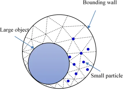
[image:2.595.329.543.571.729.2]fluid, small particles and large objects. Accordingly, thefluid-solid inter-action can be classified into two groups:fluid-small particle interaction andfluid-large object interaction, as schematically shown inFig. 1. For the large object, the inducedflow structure and its motion are resolved using a body-fitted dynamic meshing approach. Thefluid forces acting on the object are calculated directly. On the other hand, the motion of small particles is modelled using an Euler-Lagrangian method which
includes particle-particle collisions, this method is often referred to as a CFD-DEM approach. The CFD-DEM coupling between the two phases is achieved by the particle-fluid interaction at different scales: cell level for
fluid phase and particle level for particulate phase. For the complete-ness, a brief description of the developed model for thefluid-solid inter-action is given below.
2.1. Fluid phase
For thefluid phase, the governing equations are the same as those of the conventional Two Fluid Model (TFM)[45], referred as model A and have been adopted in Fluent as the Eulerian multiphase model, given as,
∂ ερf
∂t þ∇∙ ερfu
¼0 ð1Þ
∂ ερfu
∂t þ∇∙ ερfuu
¼−ε∇P−Spþ∇∙ ετf
þερfg ð2Þ
whereρf,P,τfandgare thefluid density, pressure shared by two phases,
the viscous stress tensor and the acceleration due to gravity, respective-ly.εis the volume fraction offluid in each cell.Spis the source term due
to the rate of momentum exchange between thefluid phase and the particulate phase.
2.2. Solid phase
For the solid phase, both the large object and the small particles are treated as discrete elements whose motion can be described by Newton's second law of motion, written as,
mdv
dt¼Ff þFcþmg ð3Þ
Idω
dt ¼TfþTc ð4Þ
wherem,I,vandωare, the mass, inertia, translational and rotational ve-locities of the element, respectively. The force and torques acting on each element consists of several contributions, the hydrodynamic com-ponents,FfandTf, arising fromfluid-solid interaction, the collision
com-ponents,FcandTc, due to solid-solid interaction and gravity. Iffine
particles or cohesive particles are involved, other non-contact forces, such as van der Waals force and capillary force, have to be considered. The collisions between particles are handled by a soft-sphere model that allows for inter-particle overlap. The collision force includes the normal contact forceFn, normal damping forceFd,n, tangential contact
forceFtand tangential damping forceFd,twhile the collision torqueTc
is composed ofTtcaused by tangential force andTrdue to particle rolling
friction resulting from the elastic hysteresis losses or viscous dissipation
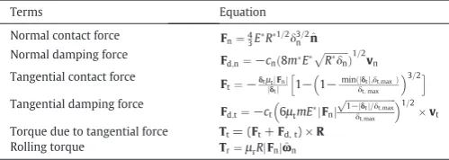
[46]. The calculation of collision forces is based on the magnitude of overlap, in which the normal contact behaviour is described by Hertz theory while the tangential elastic frictional contact is based on Mindlin and Deresiewicz theory[47].Table 1lists the equations used in the cal-culation. The details can be found elsewhere[48].
2.3. Phase coupling
The calculation of thefluid-solid interaction differs between the large objects and the small particles. For the large objects, the force and torque due tofluidflow are fully resolved at each CFD time-step, de-termined by the integration offluid stressσon its surface.
Ff ¼∯σ∙n^dS ð5Þ
Tf¼∯Rðσ∙n^ÞdS ð6Þ
However, for the small particles, forces caused byfluidflow are modelled. Thefluid-particle interaction is resolved at thefluid cell level. The totalfluid-particle interaction force can be split into a pressure gradient force and a drag force.
Ff¼−Vp∇PþFd ð7Þ
whereVp,∇PandFdare, respectively, the volume of the particle,
pres-sure gradient and drag force. The particle drag forceFdis determined
by cell-averaged porosity,flow velocity and particle velocity, given as,
Fd¼β
Vp
1−εðu−vÞ ð8Þ
withβthe interphase momentum exchange coefficient.
[image:3.595.302.552.77.166.2]To test the impact of drag model on bubbling behaviour, drag model proposed by Beetstra et al.[49]and drag model of Ergun and Wen & Yu
[50,51]are used in this work. The Beetstra model is derived from Lattice-Boltzmann simulation and is valid over a wide range of Reynolds numbers. Accordingly, the interphase momentum exchange coefficient,
β, is given as,
β¼Aμ
d2
1−ε
ð Þ2
ε þBdμ2
1−ε
ε Rep ð9Þ
in which the particle Reynolds number Repis defined as Rep=ρdpε|u− vp|/μ. The coefficientA¼180þ18ε4ð1þ1:5
ffiffiffiffiffiffiffiffiffiffi
1−ε p
Þ=ð1−εÞand coeffi -cientB= 0.31(ε−1+ 3ε(1−ε) + 8.4Re
p
−0.343)/(1 + 103(1−ε)Re p 2ε−2.5).
On the other hand, the drag model of Ergun and Wen & Yu is based on ex-perimental measurements. The interphase momentum exchange coeffi -cient,β, is given as,
β¼
150μð1−εÞ 2
εd2p
þ1::75ð1−εÞρf
dp u−v p
ðεb0:8Þ
3 4CD
εð1−εÞ dp ρf u−vp
ε−2:65 ðεN0:8Þ
8 > > > < > > > :
ð10Þ
whereCD= 24(1.0 + 0.15Rep0.687)/Repwhen Repb1000 andCD= 0.44
when RepN1000.
The rate of momentum exchange in the right of Eq.(2)is calculated by summing up the drag force acting on particles in afluid cell so that Newton's third law of motion is satisfied[13], given by,
Sp¼ 1
Vcell
XNpc
n¼1
βVpu−vp
1−ε ð11Þ
Table 1
Equations used to calculate forces and torques in this work.
Terms Equation
Normal contact force Fn¼43ER1=2δ3=2n n^
Normal damping force F
d;n¼−cnð8mE
ffiffiffiffiffiffiffiffiffiffi Rδn
p Þ1=2vn
Tangential contact force
Ft¼−δtμjδtjtFnj j
h
1−1−minðjδtj;δt;maxÞ
δt;max
3=2i
Tangential damping force
Fd;t¼−ct
6μtmEjFnj
ffiffiffiffiffiffiffiffiffiffiffiffiffiffiffiffiffiffiffiffiffi
1−jδtj=δt;max
p
δt;max
1=2
vt
Torque due to tangential force Tt= (Ft+Fd, t) ×R
Rolling torque Tr¼μrRjFnjω^n
Where 1/R∗= 1/Ri+ 1/Rj, withRiandRjbeing the radius of two particles in contact, 1/E∗=
(1−νi2)/Ei+ (1−νj2)/Ej, withEandνthe Young's Modulus and Poisson's ratio,
respectively;δnandδtrepresent the overlap in normal and tangential directions;
δt, max=μt((2−ν)/(2−2ν))δn, withμtthe sliding friction andμrthe rolling friction;
^
ωn¼ωn=jωnjwithωnthe angular velocity;cn¼−lne=
ffiffiffiffiffiffiffiffiffiffiffiffiffiffiffiffiffiffiffiffiffi π2þln2e
p
withVcellbeing the volume of afluid cell andNpcthe number of particles
in thefluid cell.
In CFD calculation,flow properties, such as velocity, pressure and its gradients, are normally stored at the cell centre. To calculate thefluid force, Eulerian properties at thefluid cell level needs to be mapped to the particle position. To this end, a linear interpolation is employed in the present work. Flow property at the particle position is determined as,
ϕp¼ϕcellþ∇ϕcell∙dr ð12Þ
whereϕpandϕcellare thefluid properties at particle position and the
cell centre;dris the distance vector directing from cell centre to particle position. The gradient offluid property∇ϕcellat each cell is calculated
using the divergence theorem[22],
∇ϕcell¼
1
ΔV X
Nface
f
ϕfAf ð13Þ
withϕfbeing thefluid property at each face calculated by averaging
from two cells adjacent to the face.
2.4. Implementation on ANSYS Fluent
Commercial CFD code, ANSYS Fluent v17.1, has been used as the modelling platform which solves the Navier-Stokes equations based on FVM. The use of ANSYS/Fluent allows us to handle internal large ob-ject with complex geometries and the re-meshing process can be han-dled efficiently. To accurately describe the inducedflow structure, the computational mesh is composed of two parts: prism boundary layer at-tached to the surface of the moving large object and tetrahedral part containing the rest of the domain. The body-fitted tetrahedral mesh is used due to its compatibility with the dynamic meshing.Re-meshing is triggered only when the skewness and size of the mesh exceed spec-ified thresholds. Consequently,flowfield around the large object is fully resolved. The present model can overcome the inaccuracy caused by staircase approximation of the moving boundary. The force and torque on the large object due tofluidflow are calculated by integrating pres-sure and viscous stress over the surface of the large object. Meanwhile, collision with small particles and bounding walls are explicitly modelled by the soft-sphere DEM model. Consequently, the large object interacts explicitly withfluidflow, bounding walls and small particles. The mo-tion of large object is described by Newton's law of momo-tion, like that of small particles but using a time-step same as that of the CFD calculation. Therefore, CFD time-step is also affected by the mass, size and stiffness of the large object. At the end of each CFD time-step, the updated linear and angular velocity are assigned to the large object as a boundary con-dition. The displacement of the large object is then enforced by the CFD solver and is accommodated by dynamic meshing, thus leading to a two-way coupling between thefluidflow and the large object.
The coupling betweenfluid and the small particles, on the other hand, are implemented byfirst performing the CFD calculation for one CFD time-step and subsequently evaluating thefluid forces acting on in-dividual particle based on the updatedflowfield. Particles are then ad-vanced at a smaller DEM time-step until synchronized with the CFD time, yielding updated particle information, such as particle position and velocity. These information are then used to renew volume fraction at eachfluid cell and to update momentum exchange term for the CFD calculation at next time-step. This calculation cycle continues until reaching the total simulation time. In general, the present model takes advantage of the conventional CFD-DEM approach whilst capturing the dynamic of the large object in particle-fluidflows.
The algorithm is implemented in Fluent based on the Eulerian multi-phase model by means of its User Defined Functions (UDFs).Fig. 2shows theflow chart of the algorithm of the UDFs which are called at the end of
each CFD time-step through macro DEFINE_EXECUTE_AT_END. User
de-fined memories (UDMs) are used to store cell-based information, includ-ing the volume fraction and the momentum exchange terms. The implemented algorithm supports both serial and parallel calculation of theflowfield. For the small particles, the DEM loop for the small particles may be executed multiple times due to the difference in time-steps be-tween CFD and DEM calculation. To calculatefluid force acting on the small particles, the CFD cell in which the particle of interest resides needs to be identified in order to map the Eulerian properties to the small particles. For parallel computing, particle properties, including position, velocity and diameter, are first broadcast from host to node. Searching of the cell is then conducted by using macro DPM_Locate_Point together with macro DPM_Init_Oct_Tree_Search for initialization and DPM_End_Oct_Tree_Search for clean-up of the memo-ry. Both the initialization and clean-up are called at every CFD time-step only if the dynamic meshing is enabled. The dynamics of the large object, translational and rotational velocities, are fed back to the Fluent through macro DEFINE_CG_MOTION while the momentum sources are added to the governing equations by macro DEFINE_SOURCE.
3. Results and discussion
To develop confidence in the proposed model, it is essential to vali-date against well-defined experiments. In the present study, two differ-entfluidized bed test cases are adopted for this purpose. Thefirst case tests the validity of the developed CFD-DEM method implemented in Fluent by comparing the predicted time-averaged velocity and porosity profiles with both experiments and previous simulations. The second case tests the capability of the present model in the prediction of bubble formation and propagation in a spouted bed and evaluates the perfor-mance of two alternative drag models. The ability of the model to deal with a large object is then demonstrated by simulating afluidized bed with an immersed tube. Initially the tube is kept stationary in order to confirm the capability of the present model in handling an unstructured mesh. The tube is then allowed to move freely and the capability of the present model to address a free-body FSI problem in a dispersed particle-fluidflow is demonstrated.
For all the simulated cases, phase coupled SIMPLE scheme was used for pressure-velocity coupling. The least squares cell based gradient method was adopted for gradient while QUICK scheme was used for momentum. The method has second order of accuracy in both time and space. The gasflow was introduced uniformly from the bottom of thefluidized bed by means of a velocity-inlet boundary condition. The top of the bed was specified as pressure outlet while no-slip boundary conditions were applied to the bounding walls. At each time-step, the residual for each governing equation was controlled below 10−5for
convergence. In this study, the turbulent gasflow is modelled by the standard k-epsilon model since the impact of turbulence on the velocity
filed is minor for dense particleflow[28].
3.1. Fluidized bed
Afluidized bed with dimension of 44 mm × 10 mm × 120 mm was simulated, for which time-averaged porosity distribution[52]and ve-locity profiles of the particles[53]measured by magnetic resonance (MR) are available. The drag law of Beetstra[49]derived from Lattice Boltzmann simulation is adopted here to simulate thefluidization of poppy seeds in their experiments, as it gives a slightly better predictions according to a comparison made by Muller et al.[52].
influence of gravity to form a packed bed. The bed is thenfluidized with a superficial gas velocity of 0.9 m/s, corresponding to 3 times the mini-mumfluidization velocity. A total physical time of 20 s is simulated. Transient results are recorded every 10 ms for post-processing.
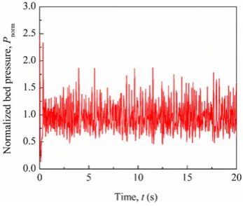
The pressure drop across thefluidized bed is a critical parameter normally used to determine the minimumfluidization velocity.Fig. 3
shows the temporal variation of pressure drop normalized by the pressure caused by bed weight. The pressure drop reflects the dynamic
behaviour of the bed. It rises sharply shortly after introducing thefl uid-izing gas and then falls rapidly andfluctuates around the value of 1.0. Thefluctuations of the pressure drop are an indication of the bubbling behaviour, as bubbles repeatedly emerge from the bottom and travel through the bed before erupting at the top.
The bubbling behaviour is readily revealed by the particleflow pat-tern. The general observations are similar as those reported by Muller
CFD solver
Calculate fluid force & moment on large object
Calculate force between large object and walls & small particles
Calculate fluid forces on small particles
Calculate collision force between small particles
Calculate collision force between small particles and large object
Update small particles: velocities & positions
Update dynamics of large object Calculate cell volume fraction
and momentum source terms
Synchronized with CFD time? Calculate collision force between
small particles and walls
Yes
No
DEM calculation of small particles with the influence of fluid flow, large object and walls.
Calculation of large object with the influence of fluid flow, small particles and walls.
Call UDF at the end of each CFD time-step
[image:5.595.129.461.54.461.2]Return to CFD calculation
[image:5.595.340.514.581.728.2]Fig. 2.Flow chart of the algorithm of the UDF implementation of the CFD-DEM coupled with dynamic meshing approach.
Table 2
Parameters used in simulation.
Parameters Value
Particle number,Np 9240
density,ρp(kg/m3) 1000
Particle diameter,dp(mm) 1.2
Young's modulus,E(Pa) 1.0 × 10⁸
Poisson ratio,ν 0.3
Rollingfiction coefficient,μr 0.2
Sliding friction coefficient,μt 0.1
Normal restitution coefficient,en 0.98
Tangential damping coefficient,ct 0.02
Temperature of gas,Tg(K) 298
Viscosity of gas,μg(kg/(s·m)) 1.8 × 10⁻⁵
Superficial gas velocity,vg(m/s) 0.9
[image:5.595.46.271.621.743.2]et al.[52]. Thefluidization quickly stabilizes and a repeatable particle
flow pattern is clearly observed. A single bubble grows on the distribu-tor plate before detaching, the particles rising on top of the bubble and falling back under gravity as it passes. A typical representation of the bubble is shown inFig. 4a, in which a single, large bubble can be seen. As pointed out by Muller et al.[52], this bubbling behaviour is mainly caused by the fairly small size of the bed. A snapshot of the particle ve-locities corresponding toFig.4a is shown inFig. 4b. For clarity, only par-ticles located in the 1.2 mm thick central slice of the bed are shown. It can be seen that particles are moving upward in the central region while downward in the vicinity of the walls. This typical core-annular
flow pattern captured by the present simulation agrees with the previ-ous results reported[52]. The corresponding gas behaviour is presented inFig. 4c. The vector represents the direction of gasflow while the con-tour denotes the magnitude of the gas velocity. Again, the gas behaviour observed by Muller et al.[52]is qualitatively captured by the present simulation, in which the gas moves upwards quickly in the bubble re-gion and recirculates at the left and right side of the bubble.
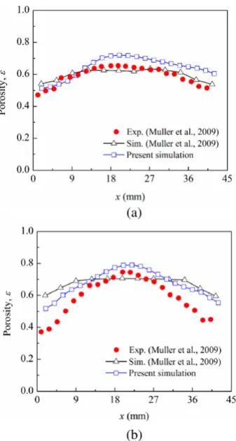
To make a quantitative comparison, time-averaged volume fraction and particle velocity is extracted and compared. The numerical results during the start-up period, approximately 3 s, are excluded to make a statistically meaningful comparison with the experiments.Fig. 5 com-pares the time-averaged porosity profiles with both experiments and CFD-DEM results reported in Muller et al.[52]at two heights above the distributor plate: 16.4 and 31.2 mm. In general, the present results are comparable with the experimental data but slightly over-predict the porosity especially in the vicinity of the side walls, similarfindings are also reported in other validation tests of CFD-DEM methods[54, 55]. At the height of 16.4 mm, the maximum difference between the predicted values and the experimental values is within 20% relative to the experimental value. At the height of 31.2 mm, the difference is smaller than 10% in the middle part of the bed while slightly larger than 10% near the side walls. Compared to the simulation results of Muller et al.[52], the present prediction is closer to the experimental data. However, it should be noted that the present simulation shows slightly large porosities in the central region of the bed than that of the results predicted by Muller et al.[52]. It can be attributed to the ad-ditional rolling resistance introduced by the rolling friction model adopted in the present simulation. Therefore, less kinetic energy is con-sumed by particle rotation and more energy is transformed into transla-tional motion. However, the particles in the current simulation belong to Geldart's Group D, consequently their behaviour is mainly dominated by the gas hydrodynamics.
Further validation is made against the time-averaged vertical parti-cle velocity.Fig. 6compares the time-averaged velocity profile of particles with experiments at three different heights: 15 mm, 25 mm and 35 mm. A better match in the central region is obtain by the present model than that of the CFD-DEM simulation in[53]. The major differ-ence with the experimental observation is the up-turning tail of velocity profile in the vicinity of the side walls. This discrepancy may be related to factors like the use of spherical particle shape instead of real shape of the poppy seeds, particle-wall collision model, mesh resolution and
[image:6.595.352.521.51.367.2](a) (b) (c)
Fig. 4.(a) A typical bubble, in which particles are coloured by the magnitude of velocity; (b) snapshot of the vertical velocity of particles in the bubblingfluidized bed. Only particles with centres located in the 1.2 mm thick central slice of the bed are shown; (c) snapshot of the gas velocity in the middle plane of the bed. Thefluidization velocity is 0.9 m/s.
(a)
[image:6.595.92.512.531.719.2](b)
turbulence modelling. A drag model which considers the effect of parti-cle shape is expected to improve the numerical prediction. In general, both the qualitative and quantitative agreement confirms that the present model has captured the key feature of thisfluidization system, which verifies our CFD-DEM method on the platform of Fluent.
3.2. Spout-bed
The mixing and segregation behaviour offluidized bed are found to be strongly influenced by bubble characteristics and dynamics[56]. In this section, the capability of the present model in the prediction of bub-ble formation and propagation is tested in a spout bed. A single bubbub-ble is injected in a pseudo-2Dfluidized bed at incipientfluidization condi-tions. Comparisons with experimental data obtained by Particle Image Velocimetry (PIV) are made in terms of bubble shape and velocity
pro-file of the particles around the bubble. The experiments were performed
by Bokkers et al.[56]in a bed with dimensions of 15 × 150 × 1000 mm and with a central jet of 10 mm width. A total number of 30,000 glass beads of 2.5 mm diameter are used in the simulation. The computation-al domain is discretised into hexahedrcomputation-al mesh with 15 × 3 × 45 cells. Other simulation parameters are listed inTable 3. The simulation starts with random generation of particles in the rectangular box, followed by particle packing under gravity until velocities of all particles are negligi-ble. Then, a jet at a velocity of 20 m/s is injected from the central orifice for a duration of 0.15 s while introducing background gas at a velocity of 1.2 m/s uniformly from the rest of the bottom.
To examine the influence of drag model on the bubble shape, two different drag models are considered: the drag model of Beetstra[49]
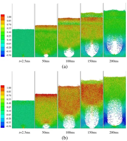
as used above and the drag model of Ergun and Wen & Yu[50,51]. To en-sure the results are comparable, both cases are started from the same packing condition. The bubble formation shows dependence on the drag model, which can be readily demonstrated by the particleflow pattern.Fig. 7shows the particle distributions during single bubble injection at different times predicted by two drag models, in which par-ticles are coloured by the vertical velocity. Following an initial expan-sion, the bubble gradually grows in size and moves upward over time. The interface between the top of the bubble and the bed predicted by the Beetstra model is less clear and less defined compared to that of
(a)
(b)
[image:7.595.72.245.54.531.2](c)
[image:7.595.316.539.74.172.2]Fig. 6.Comparison of profiles of vertical velocity of particles at different heights of the bed: (a) 15 mm, (b) 25 mm and (c) 35 mm.
Table 3
Parameters used in simulation.
Parameters Value
Particle number,Np 30,000
Density,ρp(kg/m3) 2526
Particle diameter,dp(mm) 2.5
Young's modulus,E(Pa) 1.0 × 10⁸
Poisson ratio,ν 0.3
Rollingfiction coefficient,μr 0.02
Sliding friction coefficient,μt 0.2
Normal restitution coefficient,en 0.97
Tangential damping coefficient,ct 0.33
t=2.5ms 50ms 100ms 150ms 200ms
(a)
t=2.5ms 50ms 100ms 150ms 200ms
(b)
Fig. 7.Particle distribution in the spout bed predicted by (a) the drag model of Beetstra
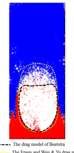
[image:7.595.303.552.433.710.2]the Ergun and Wen & Yu drag model. InFig. 8, the bubble profile is
de-fined using a critical solid volume fraction of 0.2 and compared with that obtained from experiment at 200 ms[56]. It can be seen that the bubble size is under-predicted by the Beetstra drag model and slightly over-predicted by the drag model of Ergun and Wen & Yu. In addition, the drag model of Ergun and Wen & Yu give a bed expansion closer to that of the experiments. Bokkers et al.[56]compared the drag model of Ergun and Wen & Yu with the drag model of Koch and Hill which is derived from LBM simulation. Similarly, they found that the drag model of Ergun and Wen & Yu gives a slightly larger bubble and less dif-fuse interface between the air bubble and the particles.
Fig. 9shows the vector plot of particle velocity for the two cases. The overall trends in the two cases are similar. The particles around the bub-ble are being pushed outwards and are deflected in the horizontal direc-tion, making particles moving upwards and downwards along the side
walls. Particles in the wake of the air bubble move towards the central orifice tofill the space behind the rising air bubble. Two re-circulations are formed in the bottom corners of the bed. The major dif-ference lies in the particle velocities above the bubble with a much higher magnitude using the Ergun and Wen & Yu drag relations, leading to a larger bubble size than that of the Beetstra model[49]. To sum up, the qualitative agreement with experiment confirms the capability of the present model in predicting bubble formation and propagation in a spout bed. The comparison between two drag models further illus-trates that the bubble size depends on the selection of drag model.
3.3. Fluidization with immersed tube
3.3.1. Fluidization with a stationary tube
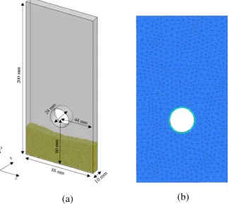
[image:8.595.101.223.50.303.2]In gas-fluidized bed, immersed tubes are often used to effectively remove/provide heat from/to the bed. The existence of immersed tube has a significant impact on the particle behaviour and heat transfer. Ex-tensive experimental studies have been conducted in this regard[10,57, 58]. In this section, a pseudo-2Dfluidized bed with an immersed tube is simulated. The purpose of this case is to demonstrate the capability of the present model in handling an unstructured mesh. Thefluidized bed has dimensions 10 mm × 88 mm × 200 mm, in which a stationary tube with diameter of 24 mm isfixed at a height of 60 mm. The geom-etry and grid representation used in the simulation are illustrated in
Fig. 10. The whole domain is discretised into tetrahedral meshes with a volume at least 3 times larger than that of a particle. In order to better capture theflow structure, the mesh size in the boundary layer on the tube is much smaller than particle size. In order to improve stability of CFD calculation, a similar procedure in[42]was adopted here to limit the solid volume fraction to 0.64 (typical random loose packing density) and redistribute source terms to neighbour cells. A total number of 20,000 particles are generated randomly without overlap above the tube to form a packed bed under gravity. The gas is then introduced uni-formly from the bottom at a constant velocity of 0.9 m/s tofluidize the bed. Other material properties used in the simulation can be found in
[image:8.595.141.462.533.728.2]Table 2.
Fig. 11shows the particleflow pattern during the initial stage offl u-idization. Particles are coloured by velocity magnitude. Particle behav-iour, especially the bubble characteristic, is strongly affected by the presence of the immersed tube. Shortly after introducing the gas, the particleflow is being divided and accelerated passing through the gap between the tube and the side walls, forming a stagnant region right below the tube (Fig. 11a). Then, due to the collision between particles and the tube, an airfilm with varying thickness is formed blow the
Fig. 8.Comparison of bubble size predicted by different drag models with experiment. The bubble is defined by a critical solid volume fraction of 0.2. Coloured layers of particles are used in the experiment[56].
(a) (b)
tube (Fig. 11b). Under the influence of gravity, an air bubble gradually grows in size underneath the tube (Fig. 11c). Asfluidization continues, defluidized particles fall back, forming a stagnant region on top of the tube. Meanwhile, the particles close to the distributor plate starts tofl u-idize again, leading to a reduction of bubble size below thefixed tube (Fig. 11d). The formation of an airfilm below the tube and a stagnant region above the tube qualitatively agree with both experimental obser-vation[59]and numerical simulation[32], thus confirming the capabil-ity of the present model in dealing with an unstructured mesh.
3.3.2. Fluidization with a free-moving tube
In order to demonstrate the key capability of the present model, namely its ability to model a large dynamic object, the previous case is
extended by allowing the immersed tube to move freely. The numerical setup is the same as the previous case, except that the density ratio be-tween moving tube and particles is set to 1.0. The upper and lower thresholds of the cell size are set as 1.2 and 0.8 times of the averaged size in the initial mesh. The threshold value of skewness for re-meshing is set to 0.75 to maintain an acceptable mesh quality.
Since the tube is free-moving, its motion is determined by the com-bined effect of gasflow, collision with small particles and confinement of the side walls. The motion of the tube will conversely introduce change to thefluidfield, further increasing the complexity of the sys-tem.Fig. 12shows the evolution of the particleflow pattern afterfl uid-ization is started. Particles are coloured by velocity magnitude. The tube sinks down shortly after thefluidization has started and bounce back
[image:9.595.133.458.58.347.2](a)
(b)
Fig. 10.(a) Geometrical and (b) numerical grid representation of thefluidized bed with an immersed tube.
(a) (b) (c) (d)
[image:9.595.132.455.536.720.2]and forth due to collision with the bounding walls. In contrast to the
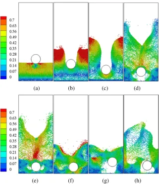
[image:10.595.139.461.50.421.2]fixed tube, there is no airfilm forming under the tube, as shown in
Fig. 12b. The particles below the tube are pushed downwards by the fall-ing tube, formfall-ing a thick layer of particles below the tube. Meanwhile, other particles are being dragged up by thefluidizing gas. InFig. 12d, shortly after the tube has hit the distributor plate, a clear gas bubble forms between the tube and the plate. The presence of the tube causes the bubble below it to split into two smaller bubbles with one on each side of the tube (Fig. 12e). The bubble on the right side of the tube grad-ually disappears as the tube begins to move towards right and particles fall down under gravity. Asfluidization continues, an air bubble is pro-duced again behind the tube after it is being blown up by the gas (Fig. 12g). Due to combined effect offluidization and the effect of the moving tube on the gasflow, large air bubbles are repeatedly formed adjacent to the tube throughout the process (Fig. 12e).
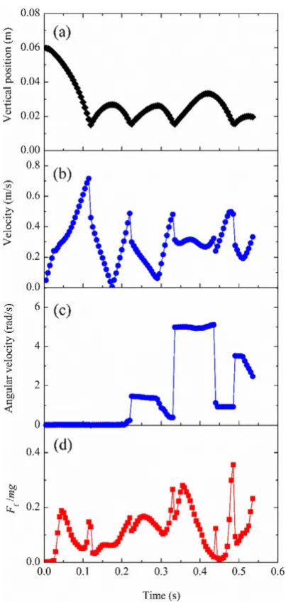
The present model permits us to not only monitor the variations in position and velocity of the internal structure but also enables a detailed understanding of its dynamics.Fig. 13shows the time history of the mo-tion andfluid force of the immersed tube duringfluidization. Only ver-tical positons are shown here. Thefluid force on the tube is normalized by the magnitude of the force due to gravity. It can be seen, for these conditions, that there is an oscillation in the vertical position of the tube. The sudden jump in the velocity is caused by the collision with the bounding walls. One distinct advantage of the present model is to allow the internal structure to rotate due to thefluid-structure interac-tion, wall collision and particle-structure interaction. In this case, the
change in the angular momentum is mainly caused by collision with thefluid bed's walls (Fig. 13c). As shown inFig. 13d, the magnitude of
fluid force acting on the tube is lower than that of gravity and thefl uc-tuations in this force are due to the bouncing motion of the tube with a magnitude significantly smaller than that of gravity, implying that the motion of the tube is dominated by the gravity and the collision with bounding walls. Although the discussion is purely based on a numerical study, the predicted dynamics highlight the complexity of the interac-tions in these systems. The unsteady, coupled, gasflow and particle
flows, and tube-wall collisions, all playing a significant role in the be-haviors observed. Clearly, it is very important to resolve theflow around the free object and accurately capture the collision dynamics when modelling systems with large objects in particlefluidflows.
4. Conclusions
In this study, a new numerical model was developed to tackle free-bodyfluid-structure interaction problems in particle-fluidflows, in which a conventional CFD-DEM method was combined with a dynamic meshing approach. Theflow structure induced by the large free-moving object was directly resolved by a body-fitted mesh while the dynamic meshing was utilized to accommodate the large object's motion, thus achieving a two-way coupling between the large object andfluidflow. On the other hand, the behaviour of small particles were captured by a coupled CFD-DEM method in which thefluid-particle interaction was model by a drag correlation. By treating the large moving object
(a) (b) (c) (d)
(e)
(f) (g) (h)
as a single element, its collision with small particles and bounding walls are handled by a soft-sphere DEM model. The proposed model has been fully implemented on a commercial software platform, ANSYS/Fluent, through its UDFs, thus allowing for the efficient handling of dynamic meshing and general application to industrial systems with complex geometries.
Validation of the CFD-DEM method has been conducted both quali-tatively and quantiquali-tatively against available literature data in the cases offluidization. The profiles of time-averaged porosity and velocity show a good quantitative agreement with experimental measurements on a gasfluidized bed. The predicted dynamics of bubble growth in a spout bed were shown to depend on drag model used, the Ergun and Wen & Yu model gave a good agreement with experiment. The charac-teristic particleflow patterns in afluidized bed with afixed tube were also captured, confirming the capability of the present model in handling an unstructured mesh. The model's ability to predictfl uid-structure interaction in particle-fluidflow was demonstrated by afl uid-ization case allowing the tube to move freely. The predicted interacting dynamics of the gas, particle and tube were highly complex and highlighted the value of fully resolving theflow around the large object. The present model shows strong potential in modelling
particle-fluidflows with complex and/or free-moving large objects, such as
milling, drug delivery and agitated chemical reactors. It enables a fully-resolvedflowfield around the moving objects but at the cost of ad-ditional computational time due to the dynamic meshing. Its application to an agitated tubular reactor with a free-moving internal agitator will be reported in the future. Experimental validation on the forced motion of the internal agitator and the inducedflowfield will be examined in more detail.
Acknowledgement
The authors would like to thank the European Commission for supporting this work as part of the research project "Intensified by Design platform for the intensification of processes involving solids handling (IbD)", under the 2020 SPIRE programme (SPIRE-08-2015-680565).
References
[1] R.R. Cai, Y.G. Zhang, Q.H. Li, A.H. Meng, Experimental characterizing the residence time distribution of large spherical objects immersed in afluidized bed, Powder Technol. 254 (2014) 22–29.
[2]Y. Zhang, B.S. Jin, W.Q. Zhong, Experimental investigation on mixing and segregation behavior of biomass particle influidized bed, Chem. Eng. Process. 48 (2009) 745–754.
[3]H.P. Cui, J.R. Grace, Fluidization of biomass particles: a review of experimental multi-phaseflow aspects, Chem. Eng. Sci. 62 (2007) 45–55.
[4]D.L. Browne, B.J. Deadman, R. Ashe, I.R. Baxendale, S.V. Ley, Continuousflow process-ing of slurries: evaluation of an agitated cell reactor, Org. Process. Res. Dev. 15 (2011) 693–697.
[5]G. Gasparini, I. Archer, E. Jones, R. Ashe, Scaling up biocatalysis reactions inflow reac-tors, Org. Process. Res. Dev. 16 (2012) 1013–1016.
[6]C. Tangsathitkulchai, Acceleration of particle breakage rates in wet batch ball milling, Powder Technol. 124 (2002) 67–75.
[7] C. Tangsathitkulchai, L.G. Austin, Slurry density effects on ball milling in a laboratory ball mill, Powder Technol. 59 (1989) 285–293.
[8] N. Islam, E. Gladki, Dry powder inhalers (DPIs) - a review of device reliability and innovation, Int. J. Pharm. 360 (2008) 1–11.
[9] H. Bai, J. Theuerkauf, P.A. Gillis, P.M. Witt, A coupled DEM and CFD simulation of
flowfield and pressure drop infixed bed reactor with randomly packed catalyst particles, Ind. Eng. Chem. Res. 48 (2009) 4060–4074.
[10] S.W. Kim, J.Y. Ahn, S.D. Kim, D.H. Lee, Heat transfer and bubble characteristics in a
fluidized bed with immersed horizontal tube bundle, Int. J. Heat Mass Transf. 46 (2003) 399–409.
[11]A.O.O. Denloye, J.S.M. Botterill, Bed to surface heat-transfer in afluidized-bed of large particles, Powder Technol. 19 (1978) 197–203.
[12]B.P.B. Hoomans, J.A.M. Kuipers, W.J. Briels, W.P.M. van Swaaij, Discrete particle simu-lation of bubble and slug formation in a two-dimensional gas-fluidised bed: a hard-sphere approach, Chem. Eng. Sci. 51 (1996) 99–118.
[13]B.H. Xu, A.B. Yu, Numerical simulation of the gas-solidflow in afluidized bed by combining discrete particle method with computationalfluid dynamics, Chem. Eng. Sci. 52 (1997) 2785–2809.
[14] Y. Tsuji, T. Kawaguchi, T. Tanaka, Discrete particle simulation of two-dimensional
fluidized-bed, Powder Technol. 77 (1993) 79–87.
[15]J.A.M. Kuipers, K.J. Vanduin, F.P.H. Vanbeckum, W.P.M. Vanswaaij, Computer-simulation of the hydrodynamics of a 2-dimensional gas-fluidized bed, Comput. Chem. Eng. 17 (1993) 839–858.
[16]J.X. Bouillard, R.W. Lyczkowski, D. Gidaspow, Porosity distributions in afluidized-bed with an immersed obstacle, AICHE J. 35 (1989) 908–922.
[17] C. Antoci, M. Gallati, S. Sibilla, Numerical simulation offluid-structure interaction by SPH, Comput. Struct. 85 (2007) 879–890.
[18] M. Robinson, M. Ramaioli, S. Luding, Fluid-particleflow simulations using two-way-coupled mesoscale SPH-DEM and validation, Int. J. Multiphase Flow 59 (2014) 121–134.
[19]M.R. Hashemi, R. Fatehi, M.T. Manzari, SPH simulation of interacting solid bodies suspended in a shearflow of an Oldroyd-Bfluid, J. Non-Newtonian Fluid Mech. 166 (2011) 1239–1252.
[20]D.G. Rong, T. Mikami, M. Horio, Particle and bubble movements around tubes im-mersed influidized beds–a numerical study, Chem. Eng. Sci. 54 (1999) 5737–5754.
[21] F.P. Di Maio, A. Di Renzo, D. Trevisan, Comparison of heat transfer models in DEM-CFD simulations offluidized beds with an immersed probe, Powder Technol. 193 (2009) 257–265.
[22]C.L. Wu, J.M. Zhan, Y.S. Li, K.S. Lam, Dense particulateflow model on unstructured mesh, Chem. Eng. Sci. 61 (2006) 5726–5741.
[23]D.Y. Liu, C.S. Bu, X.P. Chen, Development and test of CFD-DEM model for complex ge-ometry: a coupling algorithm forfluent and DEM, Comput. Chem. Eng. 58 (2013) 260–268.
[24]Y.Z. Zhao, M.Q. Jiang, Y.L. Liu, J.Y. Zheng, Particle-scale simulation of theflow and heat transfer behaviors in fluidized bed with immersed tube, AICHE J. 55 (2009) 3109–3124.
[25]Q.F. Hou, Z.Y. Zhou, A.B. Yu, Computational study of heat transfer in a bubblingfl uid-ized bed with a horizontal tube, AICHE J. 58 (2012) 1422–1434.
[image:11.595.58.260.48.473.2][26] N. Gui, J.R. Fan, K. Luo, DEM-LES study of 3-D bubblingfluidized bed with immersed tubes, Chem. Eng. Sci. 63 (2008) 3654–3663.
[27] S.L. Yang, K. Luo, J.R. Fan, K.F. Cen, Particle-scale investigation of the hydrodynamics and tube erosion property in a three-dimensional (3-D) bubblingfluidized bed with immersed tubes, Ind. Eng. Chem. Res. 53 (2014) 6896–6912.
[28] F. Alobaid, J. Strohle, B. Epple, Extended CFD/DEM model for the simulation of circu-latingfluidized bed, Adv. Powder Technol. 24 (2013) 403–415.
[29]F. Alobaid, A particle-grid method for Euler-Lagrange approach, Powder Technol. 286 (2015) 342–360.
[30] C.S. Peskin, Flow Patterns around Heart Valves - Numerical Method, J. Comput. Phys. 10 (1972) 252–&.
[31] S. Takeuchi, S. Wang, M. Rhodes, Discrete element method simulation of three-dimensional conical-base spouted beds, Powder Technol. 184 (2008) 141–150.
[32] Y. Guo, C.Y. Wu, C. Thornton, Modeling gas-particle two-phaseflows with complex and moving boundaries using DEM-CFD with an immersed boundary method, AICHE J. 59 (2013) 1075–1087.
[33] T. Tsuji, K. Higashida, Y. Okuyama, T. Tanaka, Fictitious particle method: a numerical model forflows including dense solids with large size difference, AICHE J. 60 (2014) 1606–1620.
[34] K. Higashida, K. Rai, W. Yoshimori, T. Ikegai, T. Tsuji, S. Harada, J. Oshitani, T. Tanaka, Dynamic vertical forces working on a large objectfloating in gas-fluidized bed: discrete particle simulation and Lagrangian measurement, Chem. Eng. Sci. 151 (2016) 105–115.
[35] Z.Y. Zhou, S.B. Kuang, K.W. Chu, A.B. Yu, Discrete particle simulation of particle-fluid
flow: model formulations and their applicability, J. Fluid Mech. 661 (2010) 482–510.
[36] C.L. Wu, A.S. Berrouk, K. Nandakumar, Three-dimensional discrete particle model for gas-solidfluidized beds on unstructured mesh, Chem. Eng. J. 152 (2009) 514–529.
[37] C.L. Wu, K. Nandakumar, A.S. Berrouk, H. Kruggel-Emden, Enforcing mass conserva-tion in DPM-CFD models of dense particulateflows, Chem. Eng. J. 174 (2011) 475–481.
[38] M. Afkhami, A. Hassanpour, M. Fairweather, D.O. Njobuenwu, Fully coupled LES-DEM of particle interaction and agglomeration in a turbulent channelflow, Comput. Chem. Eng. 78 (2015) 24–38.
[39] C.B. Fonte, J.A.A.O. Jr, L.C.D. Almeida, DEM-CFD coupling: mathematical modelling and case studies using Rokcy-DEM and ANSYSfluent, Eleventh International Conference on CFD in the Minerals and Process Industries, CSIRO, Melbourne, Australia, 7–9 De-cember 2015, 2015.
[40] K.W. Chu, A.B. Yu, Numerical simulation of the gas-solidflow in three-dimensional pneumatic conveying bends, Ind. Eng. Chem. Res. 47 (2008) 7058–7071.
[41] K.W. Chu, A.B. Yu, Numerical and experimental investigation of an "S-shaped" circu-latingfluidized bed, Powder Technol. 254 (2014) 460–469.
[42]H. Wahyudi, K.W. Chu, A.B. Yu, 3D particle-scale modeling of gas-solidsflow and heat transfer influidized beds with an immersed tube, Int. J. Heat Mass Transf. 97 (2016) 521–537.
[43] K.W. Chu, B. Wang, D.L. Xu, Y.X. Chen, A.B. Yu, CFD-DEM simulation of the gas-solid
flow in a cyclone separator, Chem. Eng. Sci. 66 (2011) 834–847.
[44] K.W. Chu, B. Wang, A.B. Yu, A. Vince, CFD-DEM modelling of multiphaseflow in dense medium cyclones, Powder Technol. 193 (2009) 235–247.
[45] T.B. Anderson, R. Jackson, Afluid mechanical description offluidized beds, Ind. Eng. Chem. Fundam. 6 (1967) 527–&.
[46]Y.C. Zhou, B.D. Wright, R.Y. Yang, B.H. Xu, A.B. Yu, Rolling friction in the dynamic simulation of sandpile formation, Physica A 269 (1999) 536–553.
[47] R.D. Mindlin, H. Deresiewicz, Elastic spheres in contact under varying oblique forces, J Appl Mech-T Asme 20 (1953) 327–344.
[48] Y. He, Z. Wang, T.J. Evans, A.B. Yu, R.Y. Yang, DEM study of the mechanical strength of iron ore compacts, Int. J. Miner. Process. 142 (2015) 73–81.
[49]R. Beetstra, M.A. van der Hoef, J.A.M. Kuipers, Drag force of intermediate Reynolds numberflow past mono- and bidisperse arrays of spheres, AICHE J. 53 (2007) 489–501.
[50] S. Ergun, Fluidflow through packed columns, Chem. Eng. Prog. 48 (1952) 89–94.
[51] C.Y. Wen, Y.H. Yu, Mechanics offluidization, Chem. Eng. Prog. Symp. Ser. 62 (1966) 100–111.
[52] C.R. Muller, S.A. Scott, D.J. Holland, B.C. Clarke, A.J. Sederman, J.S. Dennis, L.F. Gladden, Validation of a discrete element model using magnetic resonance measurements, Particuology 7 (2009) 297–306.
[53] C.R. Muller, D.J. Holland, A.J. Sederman, S.A. Scott, J.S. Dennis, L.F. Gladden, Granular temperature: comparison of magnetic resonance measurements with discrete ele-ment model simulations, Powder Technol. 184 (2008) 241–253.
[54] W.G. Nan, Y.S. Wang, J.Z. Wang, Numerical analysis on thefluidization dynamics of rodlike particles, Adv. Powder Technol. 27 (2016) 2265–2276.
[55] T.W. Li, R. Garg, J. Galvin, S. Pannala, Open-source MFIX-DEM software for gas-solids
flows: part II - validation studies, Powder Technol. 220 (2012) 138–150.
[56] G.A. Bokkers, M.V.S. Annaland, J.A.M. Kuipers, Mixing and segregation in a bidisperse gas-solidfluidised bed: a numerical and experimental study, Powder Technol. 140 (2004) 176–186.
[57]J.A. Doherty, R.S. Verma, S. Shrivastava, S.C. Saxena, Heat-transfer from immersed horizontal tubes of different diameter in a gas-fluidized bed, Energy 11 (1986) 773–783.
[58] J. Friedman, P. Koundakjian, D. Naylor, D. Rosero, Heat transfer to small horizontal cylinders immersed in afluidized bed, J Heat Trans-T Asme 128 (2006) 984–989.