UNIVERSITI TEKNIKAL MALAYSIA MELAKA
DEVELOPMENT OF AUTO LOG SHEET SWITCH FOR
ENERY MANAGEMENT
This report submitted in accordance with requirement of the Universiti Teknikal Malaysia Melaka (UTeM) for the Bachelor’s Degree in Electrical Engineering
Technology (Telecommunications Electronics) with Honours
By
MOHAMAD AZYWAN BIN SAPINGAI B071410153
921107146111
UNIVERSITI TEKNIKAL MALAYSIA MELAKA
BORANG PENGESAHAN STATUS LAPORAN PROJEK SARJANA MUDA
TAJUK: DEVELOPMENT OF AUTO LOG SHEET SWITCH FOR ENERGY MANAGEMENT
SESI PENGAJIAN: 2016/2017 Semester 1
Saya MOHAMAD AZYWAN BIN SAPINGAI
mengaku membenarkan Laporan PSM ini disimpan di Perpustakaan Universiti Teknikal Malaysia Melaka (UTeM) dengan syarat-syarat kegunaan seperti berikut:
1. Laporan PSM adalah hak milik Universiti Teknikal Malaysia Melaka dan penulis. 2. Perpustakaan Universiti Teknikal Malaysia Melaka dibenarkan membuat salinan
untuk tujuan pengajian sahaja dengan izin penulis.
3. Perpustakaan dibenarkan membuat salinan laporan PSM ini sebagai bahan pertukaran antara institusi pengajian tinggi.
4. **Sila tandakan ( )
SULIT
TERHAD
TIDAK TERHAD
(Mengandungi maklumat yang berdarjah keselamatan atau kepentingan Malaysia sebagaimana yang termaktub dalam AKTA RAHSIA RASMI 1972)
(Mengandungi maklumat TERHAD yang telah ditentukan oleh organisasi/badan di mana penyelidikan dijalankan)
Alamat Tetap:
No 16 Lorong 3 PPRT Batu 23
Sg Nibong 45400 Sekichan
Selangor Darul Ehsan
Tarikh: 18/01/2018
Disahkan oleh:
Cop Rasmi:
DECLARATION
I hereby, declared this report entitled “Auto Log Sheet Switch for Energy Management” is the results of my own research except as cited in references.
Signature : ……….………..
Author’s Name : MOHAMAD AZYWAN BIN SAPINGAI
APPROVAL
This report is submitted to the Faculty of Engineering Technology of UTeM as a partial fulfilment of the requirements for the degree of Bachelors of Electronics Engineering Technology (Telecommunication) with Honours. The members of the
supervisor committee are as follow:
i
ABSTRAK
Raspberry Pi adalah satu sistem computer yang besaiz kecil yang mampu
menghasilkan prestasi berkelajuan tinggi, ketepatan yang baik, fleksbiliti yang baik
dan penyelesaian kos yang rendah untuk pembuatan sistem berasaskan elektronik.
Selain itu, sistem computer ini seiring dengan penggunaan internet yang pelbagai
(IoT) yang menjadi tapak penggunaan dalam pelbagai aplikasi. Di dalam laporan ini
juga penggunaan perkakasan dan perisian juga turut dibicangkan secara terperinci
dalam melaksanakan penyimpanan maklumat bersama penggunaan Raspberry Pi 3
Model B. Penyimpanan maklumat adalah alatan elektronik yang merakam maklumat
dalam tempoh masa yang tertentu. Tujuannya utama menyimpan maklumat dan
merakamkanya suppaya dapat membantu memberi maklumat semasa ianya
diperlukan. Lembaran log adalah idea yang wujud di pelbagai tempat seperti di
sebuah institusi, organisasi mahupun di pasaran yang kebiasaanya digunakan dalam
mencatat seseorang yang bertugas dan mencatat masa serta tarikh. Sehingga hari ini,
lembaran log ini digunakan secara manual untuk mencatat dan keputusannya berlaku
pembaziran masa serta tenaga manusia. Kesannya membawa kearah kenaikan harga
penggunaan tenaga elektrik yang tidak disangka serta maklumat yang tidak lengkap.
Pembuatan projek ini mengutamakan pengumpulan dan penyimpanan maklumat yang
mengandungi masa dan tarikh semasa suis dalam keadaan berfungsi atau tidak
berfungsi bersama penggunaan raspberry pi. Malahan, pembuatan projek ini turut
menggunakan M2X portal sebagai tapak dalam menggunakan internet pelbagai dan
ini juga boleh gariskan sebagai tujuan yang utama dalam menghasilkan peranti
mudah alih serta menyediakan sistem pemantauan secara dalam talian. Sebagai hasil
daripada pembuatan projek ini adalah dapat menyelesaikan masalah kenaikan harga
penggunaan tenaga elektrik yang tidak sangka dan maklumat yang tidak lengkap.
Akhir sekali penyimpanan maklumat berasaskan penggunaan internet pelbagai (IoT)
adalah cara yang terbaik dalam pemantuan dan pengawalan kepada persekitaran
ii
ABSTRACT
iii
DEDICATION
iv
ACKNOWLEDGMENT
First of all, I would like to thank my supervisor, Sir Mohd Khanapiah Bin Nor for giving me this chance to have my final year project under his supervision. I would also like to express my appreciation towards him by giving me the motivation, guidance and discussion along with this project. He still managed to guide me along by suggesting me the solutions for every challenge that I had faced despite they are being busy with their jobs and duties.
The most important one, I wish to express my deepest appreciation to my family for the unceasing support and attention in my entire study. Their endless support has encouraged me to face any challenge throughout these four years’ study in UTeM.
v
TABLE OF CONTENT
ABSTRAK i
ABSTRACT ii
DEDICATION iii
ACKNOWLEDGMENT iv
TABLE OF CONTENT v
LIST OF TABLES vii
LIST OF FIGURES viii
LIST OF SYMBOLS AND ABBREVIATIONS x
CHAPTER 1: INTRODUCTION 1
1.1 INTRODUCTION 1
1.2 PROJECT BACKGROUND 1
1.3 PROBLEM STATEMENT 2
1.4 OBJECTIVES 2
1.5 SCOPE OF WORK 2
1.6 THESIS OUTLINE 3
CHAPTER 2: LITERATURE REVIEW 4
2.1 INTRODUCTION 4
2.2 PREVIOUS RELATED WORK 4
2.2.1 IOT Based Data Logger for Monitoring and Controlling
Equipment Working Status and Environmental Conditions 4 2.2.2 An IoT Application for Environmental Monitoring and Control
Using Raspberry-Pi 9
2.2.3 An IoT Based Real-Time Weather Monitoring System Using
Raspberry Pi 13
2.2.4 Humidity and Temperature Monitoring By Using Cloud Network 17
2.3 HARDWARE DESCRIPTION 21
2.3.1 Raspberry Pi 3 Model B 21
vi
2.4 SOFTWARE DESCRIPTION 28
2.4.1 Python 28
2.4.2 AT & T M2X (IoT) Platform 31
CHAPTER 3: METHODOLOGY 34
3.1 INTRODUCTION 34
3.2 SYSTEM OVERVIEW 35
3.3 FLOWCHART OF OVERALL PROGRESS 37
3.4 PROJECT METHODOLOGY 39
3.5 FLOWCHART OF PROJECT DEVELOPMENT 40
CHAPTER 4: RESULT & DISCUSSION 43
4.1 INTRODUCTION 43
4.2 AUTO LOG SHEET SWITCH SYSTEM 43
4.2.1 Hardware Result 44
4.2.2 Software Result 50
4.2.2.1 Raspberry Pi Activity Log (Offline) 50
4.2.2.2 M2X Portal (Online) 52
4.3 PROJECT ANALYSIS 54
4.3.1 Analysis on the Auto Log Sheet Switch with Different Time 54
4.4 DISCUSSION 58
CHAPTER 5: CONCLUSION &FUTURE WORK 61
5.1 INTRODUCTION 61
5.2 CONCLUSION 61
5.3 RECOMMENDATION OF FUTURE WORK 62
REFERENCES 63
APPENDICES 65
APPENDIX A 66
APPENDIX B 74
vii
LIST OF TABLES
Table 2.1 - Comparison of raspberry pi model and type 24
Table 2.2 - Pin USB port device description 27
Table 3.1 - Gantt chart 42
Table 4.1 - Raspberry Pi pin description 48
Table 4.2 - Duration time for each lamp 57
viii
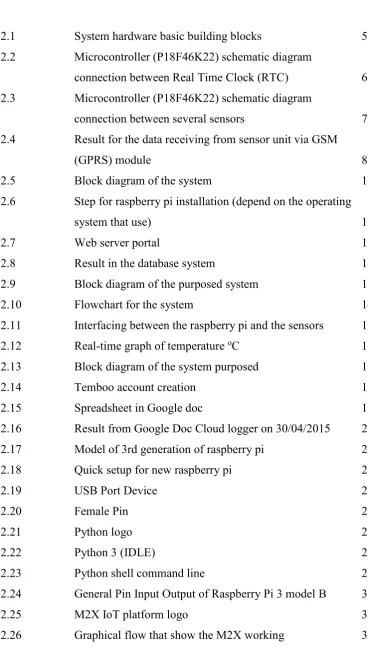
LIST OF FIGURES
Figure 2.1 System hardware basic building blocks 5
Figure 2.2 Microcontroller (P18F46K22) schematic diagram
connection between Real Time Clock (RTC) 6 Figure 2.3 Microcontroller (P18F46K22) schematic diagram
connection between several sensors 7 Figure 2.4 Result for the data receiving from sensor unit via GSM
(GPRS) module 8
Figure 2.5 Block diagram of the system 10
Figure 2.6 Step for raspberry pi installation (depend on the operating
system that use) 11
Figure 2.7 Web server portal 12
Figure 2.8 Result in the database system 12
Figure 2.9 Block diagram of the purposed system 13
Figure 2.10 Flowchart for the system 14
Figure 2.11 Interfacing between the raspberry pi and the sensors 16 Figure 2.12 Real-time graph of temperature oC 16
Figure 2.13 Block diagram of the system purposed 18
Figure 2.14 Temboo account creation 19
Figure 2.15 Spreadsheet in Google doc 19
Figure 2.16 Result from Google Doc Cloud logger on 30/04/2015 20 Figure 2.17 Model of 3rd generation of raspberry pi 22
Figure 2.18 Quick setup for new raspberry pi 25
Figure 2.19 USB Port Device 26
Figure 2.20 Female Pin 27
Figure 2.21 Python logo 28
Figure 2.22 Python 3 (IDLE) 29
Figure 2.23 Python shell command line 29
Figure 2.24 General Pin Input Output of Raspberry Pi 3 model B 30
Figure 2.25 M2X IoT platform logo 31
ix Figure 2.27 Illustrate the connection between the devices
and M2X portal 33
Figure 3.1 Overall flowcharts for PSM 34
Figure 3.2 Overall system architecture 36
Figure 3.3 Block diagram for Auto Log Sheet Switch system 36
Figure 3.4 Flowchart for the overall system 38
Figure 3.5 Flowchart of Project Development 40
[image:14.595.135.518.86.732.2]Figure 4.1 Prototype of Auto Log Sheet Switch System 44 Figure 4.2 Internal view of Auto Log Sheet Switch System 45
Figure 4.3 Labelled for switch and lamp 46
Figure 4.4 Switch pin configuration 47
Figure 4.5 Pin connection between raspberry pi 47
Figure 4.6 Testing to the Lamp A, Lamp B, Lamp C, and Lamp D 49 Figure 4.7 Main view of Raspberry Pi Activity Log 51 Figure 4.8 Logger in excel file of Raspberry Pi Activity Log 51
Figure 4.9 Raspberry Pi Ip address 51
Figure 4.10 Login page for the M2X portal 52
Figure 4.11 Dashboard for the M2X portal 53
Figure 4.12 Data logger in excel file for the M2X portal 53 Figure 4.13 Main view of Raspberry Pi Activity Log 54
Figure 4.14 Dashboard for the M2X portal 54
Figure 4.15 Raspberry Pi Activity Log download 55 Figure 4.16 Raspberry Pi Activity Log data export 55 Figure 4.17 Logger in excel file of Raspberry Pi Activity Log 56 Figure 4.18 Data logger in excel file for the M2X portal which following
Coordinated Universal Time (UTC) 57
Figure 4.19 Coding for setup the time and date for dashboard 59
x
LIST OF ABBREVIATIONS, SYMBOLS AND
NOMENCLATURE
IOT - Internet of Thing DAQ - Data Acquisition LCD - Liquid Crystal Display PCB - Printed Circuit Board RTC - Real Time Clock
IR - Infrared
SD - Secure Digital
I/O - Input or Output
IDE - Integrated Development Environment GUI - Graphical User Interface
AC - Alternating Current
DC - Direct Current
GND - Ground
SPI - Serial Peripheral Interface CSV - Comma separated value
GPS - Global System for Mobile Communication GSM - Global System for Mobile Communication GPRS - General Packet Radio Service
ADC - Analog to Digital Converter PIC - Peripheral Interface Controller
ROM - Read Only Memory
RAM - Random Access Memory LED - Light Emitting Diodes MBps - Megabytes Per Second
IDLE - Integrated Development Learning Environment GPIO - General Purpose Input Output
xi WI-FI - Wireless Fidelity
CPU - Central Processing Unit
GB - Gigabyte
USB - Universal Serial Bus
1
CHAPTER 1
INTRODUCTION
1.1 Introduction
This chapter will present all the description of this research, which is about the Development of Auto Log Sheet Switch for Energy Management system using Raspberry Pi by declaring the background and the objectives and the scope of this project. The objectives of this project are to solve the problem statement of high consumption electrical equipment such as floodlight at a stadium, chiller etc. that declared in this chapter.
1.2 Background of Project
2
made in which a system to record the data automatically. As a result, the Development of Auto Log Sheet Switch for Energy Management is the title of project name is present which could be used to record the data that consist time and date since the switch is an on/off switch.
1.3 Problem Statement
The most common way of tracking log sheet book is either by calling out the person names who was in charge or by asking them to provide the log sheet where the data or the information that was filled manually. There is some highlight the drawbacks in the next sentence to using the system when the book is used as a log sheet to record data such as time and date. Besides that, this may occur to someone is capable to write the wrong information, and this will cause an unexpected of electricity bill increase[1]. Furthermore, this log sheet book may have lost as it is in a hardcopy. Because of that, this log sheet cannot be managed properly and will cause a problem to some organization in order to have a review or do the monitoring[2].
1.4 Objectives
a) To study and develop a portable Auto Log Sheet Switch System
b) To collect and store the data that consist time and date since the switch is an on/off switch.
1.5 Scope of work
3
through the M2X which is a platform to theInternet of Things (IoT). For example, the situation in stadium Kompleks Sukan UTeM, when the switch for high voltage spotlight as known as ‘Flood Light’ is on and it will trigger the relay module that recommended for the future study. By using the LED that act as an output result and at the same time after the switch is turning on or off the data will be recorded in the internal storage Raspberry Pi. After that, the data will be sent to the portal M2X for the public reviews as a reference. Next, this system is fully controlled by using Raspberry Pi and as described previously, the recorded data can be extract from the Raspberry Pi internal storage and M2X portal that can viewed via computer.
1.6 Thesis Outline
This report consists of four chapters that will describe the flow of this project. The first chapter consists of the background of this project, problem statement, objectives and the work scope of this project.
Whilst for the second chapter consists of the literature review in which this part is used to compare the ideas of other researcher and to do some analysis on possible hardware and software to be used in this project.
The third chapter is about the methodology that will explain the method that will be used to do the analysis of this research project.
Fourth chapter will reveal the result that had obtained from the analysis and the discussion made through the output that obtained from the analysis that had made.
4
CHAPTER 2
LITERATURE REVIEW
2.1 Introduction
This chapter will discuss about the concept and the method to be used in this project based on the information and the sources gathered from books, journals or website. Auto Log Sheet Switch System is a method for data recoded as known data logger. In addition, another research from other data logger also will be discussed.
2.2 Previous Related Work
2.2.1 IOT Based Data Logger for Monitoring and Controlling Equipment Working Status and Environmental Conditions
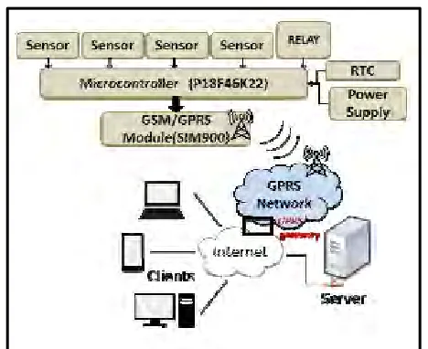
This research paper was written by Keyur K. Patel and Sunil Patel in April 2016. From this research, the idea that had been presented is to design and develop a data logger for monitoring and controlling by using IOT platform. This research also focused for controlling the environmental condition, which included the equipment working status in industry and home from any places in the world. The records data were collected and stored to database server using GSM module by added the GPRS capability[3].
5
[image:22.612.247.481.261.452.2]equipment working status and environmental condition as well as controlling will ensure that the equipment running in safety zone and under environmental protection that mentioned before as well as in energy saving mode[1]. By creating a log file, it will help to analyse the causes of the faulty equipment that stored in the database and the log file are able to become as a references for other department to ensure the reliable operation of the equipment that suitable environmental condition[4]. By this log file, it will extend equipment life and equipment maintenance cycle as well as reduces equipment failure rate.
Figure 2.1: System hardware basic building blocks (Keyur K. Patel and Sunil Patel in April 2016)
6
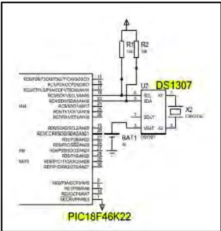
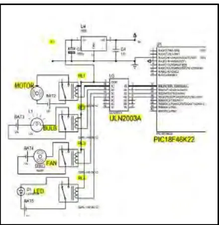
[image:23.612.254.471.139.365.2]respectively as shown in figure 2.2 and figure 2.3. Thus, the information collected by the sensors is transmitted to controlling unit. P18F46K22 has transmitting and receiving capability on it serial port[5].
Figure 2.2: Microcontroller (P18F46K22) schematic diagram connection between Real Time Clock (RTC)
7
Figure 2.3: Microcontroller (P18F46K22) schematic diagram connection between several sensors
(Keyur K. Patel and Sunil Patel in April 2016)