White Rose Research Online URL for this paper:
http://eprints.whiterose.ac.uk/125488/
Version: Accepted Version
Article:
Konstantopoulos, G. orcid.org/0000-0003-3339-6921 and Zhong, Q. (2018)
Current-limiting DC/DC power converters. IEEE Transactions on Control Systems
Technology. ISSN 1063-6536
https://doi.org/10.1109/TCST.2017.2787106
© 2018 IEEE. Personal use of this material is permitted. Permission from IEEE must be
obtained for all other users, including reprinting/ republishing this material for advertising or
promotional purposes, creating new collective works for resale or redistribution to servers
or lists, or reuse of any copyrighted components of this work in other works. Reproduced
in accordance with the publisher's self-archiving policy.
[email protected] https://eprints.whiterose.ac.uk/
Reuse
Items deposited in White Rose Research Online are protected by copyright, with all rights reserved unless indicated otherwise. They may be downloaded and/or printed for private study, or other acts as permitted by national copyright laws. The publisher or other rights holders may allow further reproduction and re-use of the full text version. This is indicated by the licence information on the White Rose Research Online record for the item.
Takedown
If you consider content in White Rose Research Online to be in breach of UK law, please notify us by
Current-limiting DC/DC Power Converters
George C. Konstantopoulos, Member, IEEE, and Qing-Chang Zhong, Fellow, IEEE
Abstract—A new nonlinear control framework that guarantees the desired regulation (voltage, current or power) with an inherent current-limiting capability for different types of dc/dc power converters is presented in this paper. This framework is based on the idea of applying a virtual resistance in series with the inductor of the converter, which changes according to nonlinear dynamics that depend on the control task. Without requiring any knowledge of the converter inductance, capacitance or the load, the controller structure is appropriately formulated for each power electronic system based on the nonlinear model of the converter. Using input-to-state stability theory, it is proven that the inductor current remains below a maximum value at all times, even during transients, independently from load and input voltage variations. This offers an inherent current-limiting property of the converter under faults, input voltage sags and unrealistic power demands without the need of external protec-tion mechanisms, saturaprotec-tion units or current limiters. Extensive simulation and experimental results validate the effectiveness of the proposed control scheme and its current-limiting property, with comparison to traditional control strategies.
Index Terms—dc/dc converters, nonlinear control, current-limiting property, protection, faults
I. INTRODUCTION
DC/DC power converters play a key role in various emerg-ing applications includemerg-ing photovoltaic systems [1], [2], wind power systems [3], electric vehicles [4], dc micro-grids [5], etc, where a voltage, current or power regulation is required and therefore a wide variety of control techniques has been proposed in the literature to achieve the desired regulation scenario. Traditional control methods introduce a Proportional-Integral (PI) controller designed based on the small-signal model of the converter [6], [7]. PI controllers are applied in a single or cascaded structure and often in combination with more advanced control methods [8]. In recent works, several of these methods have been implemented using sliding control [9] or model predictive control [10] to guarantee precise output voltage regulation under a control input constraint, which is represented by the duty ratio of the converter.
Using the average nonlinear dynamic model of the dc/dc converters [11], several nonlinear control methods have been designed to achieve the desired voltage or current regulation and guarantee the stability of the closed-loop system [12], [13]. Passivity-based controllers have been effectively applied to dc/dc converters supported by a rigorous proof of stability [14], and are often combined with the traditional PI control [15]. However, most of the existing control methods for dc/dc converters require accurate knowledge of the converter parameters (inductance, capacitance) or the load to guarantee nonlinear stability, which can change during the operation.
G. C. Konstantopoulos is with the Department of Automatic Con-trol and Systems Engineering, The University of Sheffield, Sheffield, S1 3JD, UK, tel: +44-114 22 25637, fax: +44-114 22 25683 (e-mail: [email protected]).
Q.-C. Zhong is with the Department of Electrical and Computer Engi-neering, Illinois Institute of Technology, Chicago, IL 60616, USA (e-mail: [email protected]).
More robust versions of dc/dc power converter control include the interconnection and damping assignment passivity-based
control [16], hybrid control [17] or H∞ and µ-synthesis
E +
-L
C iL
+
-v i
u loa
d
r
E +
-L
C +
-v i
u
iL
loa
d
r
E +
- L
C
+
-v
i u
iL
loa
d
r
Ldi
dt = −ri−(1−u)v+E (1)
Cdv
dt = (1−u)i−iL (2)
Ldi
dt = −ri−v+uE (3)
Cdv
dt = i−iL (4)
Ldi
dt = −ri−(1−u)v+uE (5)
Cdv
dt = (1−u)i−iL. (6)
[image:3.595.321.560.716.748.2](a) (b) (c)
Figure 1. Schematic diagram and dynamic model for main types of dc/dc power converters: (a) boost, (b) buck and (c) buck-boost
II. DYNAMIC MODEL OF DC/DC POWER CONVERTERS
All main types of power converters (boost, buck and
buck-boost) consist of an inductor L with a small resistance r
in series, a capacitor C, a diode and a switching element.
Consider asEthe dc input voltage,ithe inductor current,vthe
output voltage andiLthe load current. The schematic diagrams
of the different dc/dc power converters are shown in Fig. 1. In practice, there exists a conduction voltage drop in the diode component, but its value is very small and is often neglected. Depending on the inductor current waveform, dc/dc convert-ers operate in continuous (CCM) or discontinuous (DCM) conduction mode. CCM can be accomplished using a high
switching frequency or a larger inductor value L. Assuming
CCM operation, the nonlinear average dynamic model of each dc/dc converter can be obtained, where the control input is
defined as the duty-ratiou∈[0,1]and allows the investigation
of control design and stability analysis [11]. Hence, the boost, buck and buck-boost converter dynamics are given from (1)-(2), (3)-(4) and (5)-(6), respectively. Similarly, the average model of different dc/dc converters can be obtained, e.g. the flyback converter dynamics can be obtained from the
buck-boost converter equations (5)-(6) if one replaces vwithnvin
(5) and iwithni in (6), where n is the winding ratio of the
equivalent isolation transformer.
Note that when u= 1, both the boost and the buck-boost
converters result in a very high inductor current (equal to Er
at the steady state). Maintaining the inductor current limited and particularly below a given value is a crucial property that should be guaranteed at all times for the protection of the converter, i.e. under transients and faults. To this end, in the sequel, a controller that can achieve different regulation tasks and inherits a current-limiting property is investigated.
III. NONLINEAR CONTROL DESIGN AND ANALYSIS
A. Control framework
Since the main task is to achieve a desired regulation scenario (voltage, current or power regulation) together with a current limitation for each dc/dc power converter, a new con-trol design framework is proposed in this paper that introduces
a dynamic virtual resistancewin series with the inductor of the
converter which partially decouples the dynamics of the input current. Hence, independently from the type of converter, the goal is to achieve the closed-loop inductor current equation:
Ldi
dt =−(r+w)i+E, (7)
E +
-L
w [wmin,wmax]
i
∈
r
Figure 2. Equivalent circuit of the closed-loop current dynamics
from which it is clear that the proposed controller introduces
a dynamic virtual resistance w in series with the inductorL
and its small parasitic resistancer, as shown in Fig. 2.
In order to follow this framework and accomplish the desired task, the duty-ratio control input of each dc/dc power converter is proposed to take the form described in Table I. Similarly, for the case of the flyback converter, the control
input can be defined asu= 1− wi
nv+E. Hence, for different
types of dc/dc converters, the control inputucan be calculated
to result in the closed-loop inductor current equation (7).
Table I
PROPOSED CONTROL LAWS FOR DC/DC CONVERTERS
boost buck buck-boost duty-ratiou 1−w
vi 1+ v E−
w Ei 1−
w v+Ei
B. Design of the virtual resistance w
If the virtual resistance is designed to stay within a given range, then the inductor current can be limited below a desired value. There are many ways to design the virtual resistance to meet this goal, e.g. using saturated integrators, but may lead to integrator windup and instability. Inspired by the recently developed bounded integral control (BIC) method in [13], here the BIC structure is adopted in order to guarantee the
boundedness of w. In this paper, the BIC is applied to the
virtual resistance w and not directly to the control input u,
as suggested in [13]. Hence, further analysis regarding the converter stability and current-limiting properties is required.
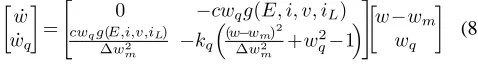
As a result, the virtual resistance wis designed to change
according to the nonlinear second-order dynamics
˙
w
˙
wq
=
"
0 −cwqg(E, i, v, iL) cwqg(E,i,v,iL)
∆w2
m −kq
(w−w m)
2
∆w2
m +w
2
q−1
#
w−wm wq
(8)
with c, kq, wm, ∆wm being positive constants with wm >
∆wmandg(E, i, v, iL) being a smooth function that describes
the desired regulation scenario, i.e. g(E, ie, ve, iLe) = 0
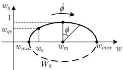
1
W0 wq
w wmax we
wqe
φɺ
wm wmin
[image:4.595.114.236.103.172.2]φ
Figure 3. Phase portrait of the controller dynamics
control task is the output voltage regulation to a reference value vref, then g(E, i, v, iL) = vref −v. Equivalently, this
function can take the form g(E, i, v, iL) = iref − i for
current regulation, g(E, i, v, iL) = Pref −viL for power
regulation, etc. The initial conditionsw0 andwq0are required
to satisfy (w0−wm)
2
∆w2
m +w
2
q0 = 1; thus a typical choice is
w0=wm, wq0= 1.
To investigate the nonlinear controller dynamics of w and
wq, consider the following Lyapunov function candidate
W = (w−wm)
2
∆w2
m
+wq2. (9)
The time derivative of W becomes
˙
W =−2kq
(w−wm)2
∆w2
m
+wq2−1
!
wq2. (10)
According to the initial conditions, it yields
˙
W = 0,⇒W(t) =W(0) = 1, ∀t≥0,
which means wandwq will start and remain on the ellipse
W0= (
w, wq ∈R:
(w−wm)2
∆w2
m
+wq2= 1
)
(11)
as shown in Fig. 3. Since the controller states
are restricted on W0, then w ∈ [wmin, wmax] =
[wm−∆wm, wm+ ∆wm],∀t ≥ 0. By considering the
mathematical transformation w = wm + ∆wmsinφ and
wq = cosφ, then one can easily prove that w and wq will
move on the ellipseW0 with an angular velocity given by
˙
φ=cwqg(E, i, v, iL) ∆wm
. (12)
Hence, assuming that the desired regulation scenario is accom-plished, i.e. g(E, i, v, iL) = 0, the angular velocity becomes
zero and the controller states can converge to two constant
valuesweandwqe(proof is given in Subsection III-D). Since
wm>∆wm>0, the ellipse W0 is located on the right-half
plane and w ∈ [wmin, wmax] > 0,∀t ≥ 0, resulting in a
positive dynamic virtual resistance.
According to (12), the angular velocityφ˙ becomes zero on
the horizontal axis, i.e. whenwq = 0 andw=wmin or w=
wmax. This is desirable to avoid a possible oscillating behavior
of the controller dynamics around the ellipseW0on thew−wq
plane. In order to further explain this, assume that during a transient, the controller states try to reach the horizontal axis.
Thenwq →0which means thatφ˙ →0independently from the
function g(E, i, v, iL). Thus, the controller states slow down
until the angular velocity changes sign. As a result,wandwq
cannot travel around the ellipseW0 and, based on the initial
conditions, they will be restricted either on the upper or the
lower semi-ellipse ofW0 as shown in Fig. 3.
Furthermore, at the limits of the virtual resistance, i.e. when
w → wmin and w → wmax, since wq → 0, then from (8)
there isw˙ →0, which means that the integration slows down
independently from the function g(E, i, v, iL). This indicates
an inherent anti-windup property of the proposed controller which smoothly slows down the integration near the limits, opposed to the case of using a saturated integrator.
C. Current-limiting property
For system (7), consider the energy stored in the inductor
V =1 2Li
2.
The time derivative of V is calculated as
˙
V =Lidi
dt =−(r+w)i
2+
Ei≤ −(r+wmin)i2+E|i|,
taking into account that w≥wmin >0,∀t≥0. Hence, for
every0< θ <1there is
˙
V ≤ −(1−θ)(r+wmin)i2−θi2+E|i|
≤ −(1−θ)(r+wmin)i2, ∀ |i| ≥ E θ(r+wmin)
,
which means that system (7) is ISS, whereE is the dc input
voltage [22]. Since E is constant (or bounded), according to
the ISS property:
˙
V <0,∀ |i|> E r+wmin
.
As a result, if initially|i(0)| ≤ E
r+wmin, then
|i(t)| ≤ E
r+wmin
,∀t≥0. (13)
Ifwmin is selected as
wmin = E imax
, (14)
where imax denotes the maximum allowed current of the
converter, then by substituting (14) into (13), there is
|i(t)| ≤ rimaximax
E + 1
< imax,∀t≥0, (15)
which guarantees the desired current-limiting property.
Assuming a constant (or bounded) input voltage E, the
current limitation results in a power limitation of all converter
types: i) for the boost converterP =Ei≤Eimax and ii) for
the buck or buck-boost converterP =Eui≤Eimax, given a
maximum value imax. Due to the small resistance r, current
i is limited slightly belowimax from (15). To overcome this
issue,wmin can be selected as wmin = imaxE −r instead of
(14), however (14) is preferred since the current limitation is still guaranteed and the controller does not require the value
ofr, which might not be accurately known. Note that the ISS
D. Asymptotic stability
The current limitation has been guaranteed independently
from iL, which can represent the current of any
voltage-controlled load, i.e. iL = f(v). For the asymptotic stability,
the case with a resistive loadRis considered for simplicity, i.e.
iL=Rv, although a similar procedure can be followed for any
voltage-controlled load (e.g. power converter-fed load [25]).
Let the closed-loop state vector x=
i v w wq T
. For any value of the virtual resistance we ∈(wmin, wmax) >0,
consider the equilibrium point xe=
ie ve we wqe
T , where for any dc/dc converterie= r+Ewe >0from (7),ve>0
and (we−wm)
2
∆w2
m +w
2
qe= 1 with wqe2 >0. Then, the Jacobian
matrix for any converter becomes
J =
J1 03×1
J2 −2kqwqe2
.
Sincekq >0andwqe2 >0, thenJ is Hurwitz ifJ1is Hurwitz where
J1=
−r+we
L 0 −
E L(r+we)
a −RC1 −b d
−cw2qe ∂g∂i
x=xe
−cwqe2 ∂g∂v
x=xe
0
.
Note that for the boost converter a = 2weE
Cve(r+we), b =
weE
2
Cv2
e(r+we)2, d =
E2
Cve(r+we)2, for the buck converter a =
1
C, b = d = 0 and for the buck-boost converter a =
2weE
C(ve+E)(r+we), b =
weE2
C(ve+E)2(r+we)2, d=
E2
C(ve+E)(r+we)2.
Thus, in every case a > 0 and b, d ≥ 0. The characteristic
equation of the system becomes
λ3+
r+we L +
1
RC +b
λ2+α1λ+α0= 0, where
α1=
r+we
L
1
RC+b
+cdw2
qe ∂g ∂v x= xe
−cw2
qe
E L(r+we)
∂g ∂i x= xe
α0=cw 2
qe
dr+we L −a
E L(r+we)
∂g ∂v x=xe
−cw2qe E L(r+we)
1
RC+b
∂g ∂i x=xe
.
Using the Ruth-Hurwitz criterion, since r+we
L +
1
RC +b >0,
then J1 will be Hurwitz and equivalently xe will be
asymp-totically stable if the following condition is satisfied:
r+we L +
1
RC +b
r+we L
1
RC +b
+cwqe2 h >0, (16) where h= d 1
RC +b
+ aE
L(r+we)
∂g ∂v
x=xe − E L2 ∂g ∂i
x=xe
.
Typically ∂g∂v x=x
e
≤0 and ∂g∂i x=x
e
≤0(g=vref−v for
volt-age regulation,g=iref−ifor current regulation). Hence, for a
current regulation scenario there is ∂g∂v
x=xe
= 0, ∂g∂i
x=xe
=−1
and therefore (16) always holds true independently from the
converter type. For a different regulation scenario, if h <0,
then the controller gain c should satisfy the inequality
c < (r+we)(1 +bRC)(rRC+weRC+L+bRLC) w2
qe(RLC)2|h|
.
(17)
Since we ∈ (wmin, wmax) > 0, then controller gain c
can be suitably defined such that (17) is satisfied for any
we∈ (wmin, wmax), where wqe2 = 1−
(we−wm)
2
∆w2
m . Note that
the rest of the controller parameters, i.e. wmax, kq, do not
affect the current-limiting property or the stability. However,
sincewminleads to a maximum currentimax, similarlywmax
will lead to a minimum inductor currentimin. Althoughimin
is theoretically zero, in practice a very small current flows
through the parasitic elements of the converter. Hence,wmax
can be selected as
wmax= E imin
, (18)
where imin can be sufficiently small (mA or µA). Having
defined the maximum and minimum values of the virtual
resistance, then the parameterswmand∆wmthat define the
ellipseW0 are given as
wm =
wmax+wmin
2 =
E(imax+imin)
2imaximin
, (19)
∆wm =
wmax−wmin
2 =
E(imax−imin)
2imaximin
. (20)
IV. OPERATION UNDER ABNORMAL CONDITIONS
A. Fault current-limiting property
Although it has been proven in the previous section that the
inductor currentiis limited independently from the regulating
function g(E, i, v, iL), i.e. even if an unrealistic reference
voltage, power or current is provided to the controller, it is important to guarantee that the current-limiting property holds under faulty conditions: i) faults in the output (e.g. short circuit) and ii) faults in the input (e.g. input voltage sag).
When a fault occurs in the output (load), the current-limiting property of the dc/dc converters is still guaranteed since the ISS property of the closed-loop current equation (7) is independent of the load. This means that the proposed controller will automatically reduce the output voltage to low values in order to guarantee the current limitation. However, the physical limitations of the dc/dc power converters should be taken into account, particularly for the boost converter
where the output voltage is always higher than the inputE. In
this case, if a short circuit occurs in the output, the current will
increase since the minimum output voltage isEindependently
from any control design (current flows through the converter diode). Assuming a resistive load in the output, the minimum
value of the load for a desired current limitation below imax
should satisfy
R≥ E imax
.
For load resistors below R, the boost converter cannot
guar-antee a current-limiting property. On the other hand, since the minimum output voltage of the buck and the buck-boost converters is zero, these two dc/dc converters can guarantee the current-limiting property under the proposed controller even if a short circuit occurs in the output.
In the second scenario, when the input voltageE drops by
a percentage p×100%, where 0 ≤ p ≤ 1, the closed-loop
current dynamics (7) become
Ldi
Then according to the same ISS analysis presented in Subsec-tion III-C, the inductor current satisfies
|i(t)|<(1−p)imax< imax,∀t≥0,
maintaining the desired current-limiting property under input voltage dips. However, the current is limited below a lower
value than imax depending on the percentage p of the input
voltage dip. Hence, a modification in the proposed controller structure is required to fully utilize the capacity of the
con-verter and limit the current at imax and not at (1−p)imax.
This is described in the sequel.
B. Extending the proposed controller to fully utilize the ca-pacity of the converter
In order to guarantee that the maximum inductor current is
imax even when the input voltage E varies, the closed-loop
current dynamics for every dc/dc converter should be
Ldi
dt =−(r+w)i+En, (22)
whereEnis the constant rated input value, opposed toEfound
in (7) which is the actual input voltage and may vary. Hence, following the same ISS analysis as described in Subsection III-C, by selecting wmin = imaxEn then|i(t)|< imax,∀t ≥0
independently from E as long as initially i(0) ≤ imax. In
this case, the maximum value of the inductor current will be
imax even if the input voltage E varies or drops below the
rated value. Hence, to achieve this task, the proposed controller described in Table I is modified to take the form given in Table
II but with the same dynamics (8). Note that when E=En,
[image:6.595.327.548.126.246.2]then the expressions of Table II become the same with the original expressions in Table I.
Table II
PROPOSED CONTROL LAWS FOR DC/DC CONVERTERS TO FULLY UTILIZE THE CONVERTER CAPACITY
boost buck buck-boost
duty-ratiou 1−w vi+
En−E
v
v+En
E −
w Ei 1−
w v+Ei+
En−E
v+E
The original controller can be useful in the boost converter case, if one compares the duty-ratio expression in Tables I and II. It is clear that the original form (Table I) does not
require the measurement of the input voltage E simplifying
the controller implementation. This is why this controller will be investigated in the experimental results in Section VI.
V. SIMULATION RESULTS
In order to test the proposed controller and compare it with traditional control strategies, all three main types of dc/dc
converters connected to a resistive load of100 Ωare simulated
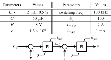
using the Simpower Systems toolbox of Matlab/Simulink. Although the average converter model was initially used for the stability analysis and the controller design, the actual switching model is tested here to verify that the developed theory holds true for the real converter system under a high switching frequency. The parameters of the system and the proposed controller are shown in Table III (same for every converter) using the controller structures from Table II with dynamics (8). The control task is to regulate the output voltage
Table III
SYSTEM AND CONTROLLER PARAMETERS(SIMULATION) Parameters Values Parameters Values
L,r 2 mH, 0.5Ω switching freq. 100kHz
C 50µF kq 100
E 48 V imax 2A
c 1.5×10⁵ i
min 1mA
PI imax
0
PI
0
u vref
v i
-iref
umax
Figure 4. Traditional cascaded PI control with current limitation [7]
to a given value vref, i.e. g(v) = vref −v. The proposed
controller is compared to a traditional cascaded PI controller with saturation units shown in Fig. 4 to achieve current limitation. The saturation of the inner loop has an upper limit
at umax, often less than 1 (physical limit of u), to avoid
very high currents. The PI gains are chosen as kpv = 0.01,
kiv = 10 for the voltage loop andkpi = 1, kii = 10for the
current loop. Since the average value of the inductor current is needed for the control implementation, a low-pass filter is applied at the measurement of the inductor current to remove the switching ripples. This filter also helps in the case of very low currents where the converter may operate in DCM to
maintain a continuous-time function for u. It is noted that
for a higher switching frequency than the one used in the simulations, the ripples of the current reduce and the actual current will be the same as the filtered one leading to a current-limiting capability for the actual current. In such a case, a low-pass filter will not be needed. In all three power converter
cases, the simulation time was limited to 0.4s due to the
limited memory of the computer and the small time step used
to obtain accurate results (0.01us). Although the simulation
was executed without sharing too much of the steady-state response, the main purpose was to clearly demonstrate both controller responses under different scenarios, i.e. i) changes of the reference voltage, ii) changes of the input voltage and iii) changes of the load.
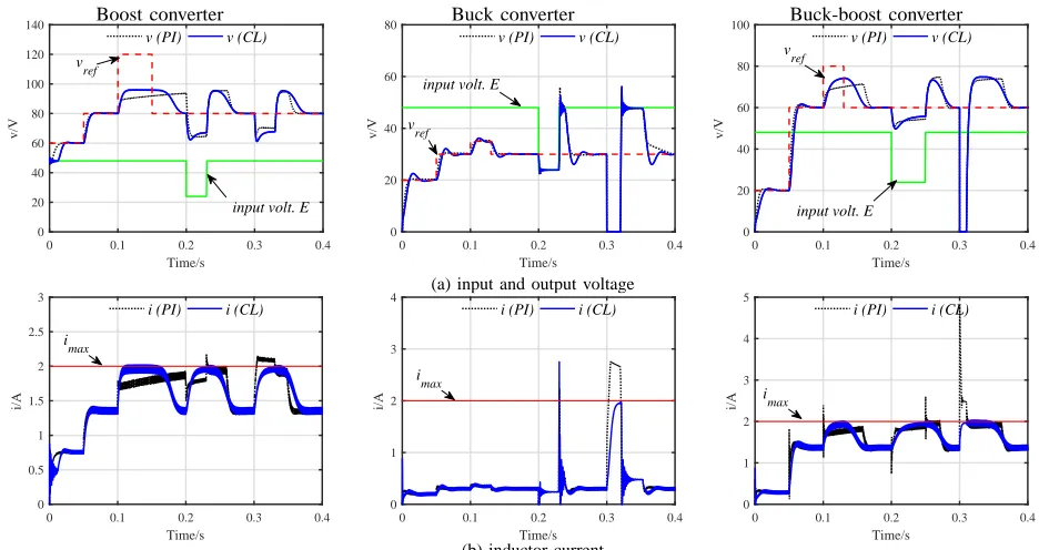
Boost converter: The output reference voltage vref is set
initially to 60V, at t = 0.05s it changes to 80V and at
t = 0.1s it increases to 120V, which will require a large
inductor current in order to test the current-limiting property of the controllers. As it is shown in the left column of
Fig. 5(a), during the first 0.1s, both controllers regulate the
output voltage at the desired level after a short transient.
However, when the reference voltagevref increases to120V,
the output voltage is regulated near 96V because i tries to
violate the maximum valueimax. Both the proposed controller
and the traditional controller guarantee the current-limiting property as clearly shown in the left column of Fig. 5(b).
At t = 0.15s, the reference vref changes back to 80V and
Boost converter Buck converter Buck-boost converter
0 0.1 0.2 0.3 0.4
Time/s 0
20 40 60 80 100 120 140
v/V
v (PI) v (CL)
input volt. E v
ref
0 0.1 0.2 0.3 0.4
Time/s 0
20 40 60 80
v/V
v (PI) v (CL)
input volt. E
v ref
0 0.1 0.2 0.3 0.4
Time/s 0
20 40 60 80 100
v/V
v (PI) v (CL)
input volt. E vref
(a) input and output voltage
0 0.1 0.2 0.3 0.4
Time/s 0
0.5 1 1.5 2 2.5 3
i/A
i (PI) i (CL)
i max
0 0.1 0.2 0.3 0.4
Time/s 0
1 2 3 4
i/A
i (PI) i (CL)
imax
0 0.1 0.2 0.3 0.4
Time/s 0
1 2 3 4 5
i/A
i (PI) i (CL)
i max
[image:7.595.66.534.100.348.2](b) inductor current
Figure 5. Simulation results with the proposed current-limiting (CL) controller and the traditional cascaded PI controller with saturation
t = 0.2s the input voltage E drops to 24V and returns to
the original value after0.03s (left column of Fig. 5(a)), while
at t = 0.3s the load resistor R changes from 100 Ωto 50 Ω
for a duration of 0.03s. In both cases, the inductor current
increases but is always limited belowimax, as expected by the
proposed controller (left column of Fig. 5(b)). However, the
traditional current-limiting method cannot maintain i below
imaxduring transients, especially after the load change, which
is a significant disadvantage compared to the proposed method.
Buck converter: Similarly, for the buck converter case
(mid-dle column of Fig. 5), initially both the proposed controller and the traditional cascaded PI controller regulate the output
voltage at the desired levels. At t = 0.2s, the input voltage
drops to 24V and returns to its original value after 0.03s.
Since the output voltage cannot be regulated at 30V due to
the inherent limitation of the converter, the voltage is regulated
at the higher possible value (24V). When the input voltage
returns to its original value, both controllers smoothly regulate
the output voltage at vref but the instantaneous value of the
current results in a peak that exceedsimax. Nevertheless, the
average inductor current is always below imax due to the
limited power of the converter, as shown in the middle column of Fig. 5(b). However, when a short circuit occurs in the output
at t = 0.3s, the proposed controller guarantees the
current-limiting property opposed to the traditional cascaded PI.
Buck-boost converter: Finally, a buck-boost converter is
investigated (right column of Fig. 5) and as in the previous
cases, when the inductor current is below imax, the output
voltage reaches the desired level. When the reference voltage
changes to 80V, the output voltage is regulated to a lower
value since the current increases and reaches the limit (right
column of Fig. 5(b)). At the time instant t= 0.2s, the input
voltage E drops to 24V for a duration of 0.05s, as shown
in the right column of Fig. 5(a), and at t = 0.3s, a short
circuit occurs at the output for 0.01s in order to test the
controller performance under abnormal conditions. In both the cases of the input voltage drop and the short circuit, with the
proposed control framework, i never violatesimax as shown
in the right column of Fig. 5(b). On the other hand, with the traditional current-limiting technique, the inductor current violates several times the limit. The current limitation is not guaranteed during the transients. Hence, it is verified that the proposed controller can protect all three types of dc/dc converters from high currents at all times, i.e. during transients, unrealistic power demands, faults. In the cases of the buck and the buck-boost converters, it can additionally protect the device from short circuits in the output. This shows the significance of having a rigorous stability proof and current limitation based on the nonlinear ISS theory. As a result, when a higher output voltage is required, the buck-boost converter should be used instead of the boost since the current limitation is maintained independently from the load. Note that although both the PI and the proposed controller can suffer from saturation in the
control input u, due to the physical limit of the converter,
the PI suffers from saturation and windup additionally in the outer loop, thus failing to guarantee the current limitation and setting the proposed scheme superior in handling the required
bounds for the system statei.
VI. EXPERIMENTAL RESULTS
To further evaluate the effectiveness of the proposed control framework, the boost converter is experimentally tested. The
input voltage E of the converter is set at 48V and the load
resistor isR= 100 Ω. The proposed controller is chosen from
Time: [400 ms/div]
i: [0.5 A/div]
E: [20 V/div]
0V
0A
v: [20 V/div]
imax vref
Time: [400 ms/div]
w: [25Ω/div]
[image:8.595.78.268.103.268.2]wq: [0.0//div]
Figure 6. Experimental results of the boost converter with the proposed controller under reference output voltage changes
In addition, different converter parameters were used due to practical limitations of the available experimental setup. Al-though the converter parameters are not optimized, the purpose of this section is to experimentally demonstrate the current-limiting controller that has been introduced for the first time in this paper. For the optimization of the converter the reader is referred to [26]. The implementation of the proposed controller is conducted in the discrete time domain by discretizing the integral functions (8) using the TMS320F28335 DSP with a sampling frequency of 16 kHz and a switching frequency
of 50kHz. As underlined in [11], the higher the sampling
frequency the more accurate the average model becomes with respect to the actual switching system. Hence, for the given sampling frequency, the delay in the discrete control implementation is small and can be ignored. Therefore, the stability analysis and the current-limiting property are valid as shown in the experimental results that follow. The different
system parameters compared to Table III are L = 2.2mH,
C= 300µF,imax= 1.5A andts= 0.05s.
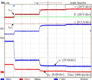
A. Change of the output voltage reference
Fig. 6 shows the time response when the reference signal
vref changes. The controller is enabled at t = 0.4s with
vref = 60V, at t = 1.6s the reference value increases to
80V and at t = 2.8s it changes to 120V. As it is shown
in Fig. 6(a), the proposed controller quickly regulates v to
vref for the first2.8s, but whenvref increases to120V, the
output voltage is regulated near 83V. The reason is that the
inductor current increases and tries to violate the maximum
valueimax= 1.5A. Fig. 6(a) shows also the current response
which increases and is limited slightly below imax, due to
the smallrwhich have been ignored in the controller design.
To understand how the controller states behave, their time
response is also shown in Fig. 6 where finally w → wmin
andwq →0 as explained in the theory.
B. Change of the load
While the proposed controller has regulated the output
voltage at vref = 60V, the load in the output changes from
100 Ω to 70 Ω. As it is shown in Fig. 7, the output voltage returns to its desired value after a very short transient. The
inductor current increases but still remains below imax.
A larger load change, i.e. from100 Ωto40 Ω, is also tested
when the output voltage reference is againvref = 60V in Fig.
8. As it is observed in Fig. 8(a), the output voltage drops after the load change. This is because the current increases and due to the current-limiting property of the converter cannot exceed
imax. Sincei→imax, then the maximum output voltage can
be calculated from the power equivalence between the input
and the output as v =√EimaxR = 53V; thus the proposed
controller leads the output voltage to this value (Fig. 8(a)). It is highlighted that according to the analysis presented in
Subsection IV-A, for the given input voltageE, the minimum
load resistance for a boost converter to achieve current-limitation with any control technique is obtained from the
power equivalence and the minimum output voltage v = E
as Rmin = imaxE = 32 Ω. This limitation does not apply
to the buck or the buck-boost converter as illustrated in the simulation results, since in these cases the current limitation is guaranteed even under a short circuit in the output.
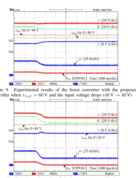
C. Change of the input voltage
In order to investigate the cases of input voltage sags,
two different scenarios are tested where E drops from 48V
to 40V (Fig. 9) and from 48V to 24V (Fig. 10), while v
is regulated at vref = 60V. In the first case, the inductor
current increases but does not violate the limit and as a result the output voltage is regulated at the desired value. In the
second case, where a 50% input voltage drop occurs, the
output voltage drops to maintain the current limiting property.
Since the original controller (Table I) is used and a 50%
input voltage drop occurs, i.e. p = 0.5, then according to
the analysis presented in Subsection IV-A, the current will be
limited below0.5imax= 0.75A. Indeed, as shown in Fig. 10,
the limit of the current drops as soon as the input voltage drops
and is limited below0.75A according to the theory. Although
the full capacity of the converter is not utilized due to the original controller used (Table I), this controller is preferred since no input voltage sensor is required andi < imaxis still
guaranteed at all times.
VII. CONCLUSIONS
A new control framework for dc/dc power converters was developed in this paper to achieve different regulation scenar-ios with a current-limiting property. The current limitation was achieved without requiring any knowledge of the converter parameters or the load and was extended to the cases of faults in the input and the output of the converter, leading to an inherent protection property of every dc/dc converter via the control design. This was accomplished without additional protection circuits, saturation units or switching actions in contrast to traditional approaches.
Future research will focus on the optimization of the converter parameters, on the analysis the proposed current-limiting framework under both CCM and DCM operation including the time delay issue in the implementation and on the design of the controller gain to further improve the transient performance and address the duty-ratio saturation issue.
REFERENCES
Time: [400 ms/div]
i: [0.5 A/div]
E: [20 V/div]
0V
0A
v: [20 V/div]
imax
Time: [400 ms/div]
w: [25Ω/div]
[image:9.595.327.561.92.398.2]wq: [0.0//div]
Figure 7. Experimental results of the boost converter with the proposed controller whenvref = 60V and the load changes from100 Ωto70 Ω
Time: [400 ms/div]
i: [0.5 A/div]
E: [20 V/div]
0V
0A
v: [20 V/div]
imax
53 V
Time: [400 ms/div]
w: [25Ω/div]
wq: [0.0//div]
Figure 8. Experimental results of the boost converter with the proposed controller whenvref = 60V and the load changes from100 Ωto40 Ω
[2] A. Ghaffari, M. Krstic, and S. Seshagiri, “Power optimization for pho-tovoltaic microconverters using multivariable newton-based extremum seeking,” IEEE Trans. Control Syst. Technol., vol. 22, no. 6, pp. 2141– 2149, Nov. 2014.
[3] Q.-C. Zhong and T. Hornik, Control of Power Inverters in Renewable Energy and Smart Grid Integration. Wiley-IEEE Press, 2013. [4] M. B. Camara, B. Dakyo, and H. Gualous, “Polynomial control method
of DC/DC converters for DC-bus voltage and currents management-battery and supercapacitors,” IEEE Trans. Power Electron., vol. 27, no. 3, pp. 1455–1467, March 2012.
[5] M. Kabalan, P. Singh, and D. Niebur, “Large signal Lyapunov-based stability studies in microgrids: A review,” IEEE Transactions on Smart Grid, to appear, early Access.
[6] J.-H. Su, J.-J. Chen, and D.-S. Wu, “Learning feedback controller design of switching converters via matlab/simulink,” IEEE Transactions on Education, vol. 45, no. 4, pp. 307–315, 2002.
[7] L. Wang, S. Chai, D. Yoo, L. Gan, and K. Ng, PID and Predictive Control of Electrical Drives and Power Converters using MATLAB / Simulink. Wiley-IEEE Press, 2014.
[8] G. Escobar, J. Leyva-Ramos, P. R. Martinez, and A. A. Valdez, “A repetitive-based controller for the boost converter to compensate the harmonic distortion of the output voltage,” IEEE Trans. on Control Syst. Technol., vol. 13, no. 3, pp. 500–508, May 2005.
[9] S. Oucheriah and L. Guo, “PWM-based adaptive sliding-mode control for boost DC–DC converters,” IEEE Trans. Ind. Electron., vol. 60, no. 8, pp. 3291–3294, 2013.
[10] S.-K. Kim, C. R. Park, J. S. Kim, and Y. I. Lee, “A stabilizing model predictive controller for voltage regulation of a DC/DC boost converter,” IEEE Trans. Control Syst. Technol., vol. 22, no. 5, pp. 2016–2023, Sept 2014.
[11] R. Ortega, A. Loria, and P. J. Nicklasson, “Passivity-based control of Euler-Lagrange systems,” in Communications and Control Engineering, 1998.
[12] S.-K. Kim and K. B. Lee, “Robust feedback-linearizing output voltage regulator for DC/DC boost converter,” IEEE Trans. Ind. Electron., vol. 62, no. 11, pp. 7127–7135, Nov 2015.
[13] G. C. Konstantopoulos, Q.-C. Zhong, B. Ren, and M. Krstic, “Bounded integral control of input-to-state practically stable nonlinear systems to guarantee closed-loop stability,” IEEE Trans. Autom. Control, vol. 61, no. 12, pp. 4196–4202, Dec 2016.
Time: [400 ms/div]
i: [0.5 A/div]
E: [20 V/div]
0V
0A
v: [20 V/div]
imaxforE=48 V
imaxforE=40 V
Time: [400 ms/div]
w: [25Ω/div]
wq: [0.0//div]
Figure 9. Experimental results of the boost converter with the proposed controller whenvref= 60V and the input voltage drops (48V→40V)
Time: [400 ms/div]
i: [0.5 A/div]
E: [20 V/div]
0V
0A
v: [20 V/div]
imaxforE=48 V
imaxforE=24 V
Time: [400 ms/div]
w: [25Ω/div]
wq: [0.0//div]
Figure 10. Experimental results of the boost converter with the proposed controller whenvref= 60V and the input voltage drops (48V→24V)
[14] Y. I. Son and I. H. Kim, “Complementary PID controller to passivity-based nonlinear control of boost converters with inductor resistance,” IEEE Trans. Control Syst. Technol., vol. 20, no. 3, pp. 826–834, May 2012.
[15] A. Jaafar, A. Alawieh, R. Ortega, E. Godoy, and Lefranc, “PI stabiliza-tion of power converters with partial state measurements,” IEEE Trans. Control Syst. Technol., vol. 21, no. 2, pp. 560–568, March 2013. [16] H. Rodriguez, R. Ortega, G. Escobar, and N. Barabanov, “A robustly
stable output feedback saturated controller for the boost dc-to-dc con-verter,” Systems & Control Letters, vol. 40, no. 1, pp. 1–8, 2000. [17] T. A. F. Theunisse, J. Chai, R. G. Sanfelice, and W. P. M. H. Heemels,
“Robust global stabilization of the DC-DC boost converter via hybrid control,” IEEE Trans. Circuits Syst. I: Reg. Papers, vol. 62, no. 4, pp. 1052–1061, Apr. 2015.
[18] S. Buso, “Design of a robust voltage controller for a buck-boost converter usingµ-synthesis,” IEEE Trans. Control Syst. Technol., vol. 7, no. 2, pp. 222–229, Mar 1999.
[19] X. Pei, S. Nie, and Y. Kang, “Switch short-circuit fault diagnosis and remedial strategy for full-bridge DC-DC converters,” IEEE Trans. Power Electron., vol. 30, no. 2, pp. 996–1004, Feb 2015.
[20] Y. Li, X. Mao, H. Wang, C. Wen, and L. Wen, “An improved hiccup mode short-circuit protection technique with effective overshoot sup-pression for DC-DC converters,” IEEE Trans. Power Electron., vol. 28, no. 2, pp. 877–885, Feb 2013.
[21] N. Bottrell and T. C. Green, “Comparison of current-limiting strategies during fault ride-through of inverters to prevent latch-up and wind-up,” IEEE Trans. Power Electron., vol. 29, no. 7, pp. 3786–3797, 2014. [22] H. K. Khalil, Nonlinear Systems. Prentice Hall, 2001.
[23] Q.-C. Zhong and G. C. Konstantopoulos, “Current-limiting droop control of grid-connected inverters,” IEEE Trans. Ind. Electron., vol. 64, no. 7, pp. 5963–5973, July 2017.
[24] G. C. Konstantopoulos and Q. C. Zhong, “Nonlinear control of dc/dc power converters with inherent current and power limitation,” in 24th Mediterranean Conference on Control and Automation (MED), June 2016, pp. 949–954.
[25] G. C. Konstantopoulos, Q.-C. Zhong, B. Ren, and M. Krstic, “Bounded droop controller for parallel operation of inverters,” Automatica, vol. 53, pp. 320 – 328, 2015.
[image:9.595.66.462.97.394.2]