UNIVERSITI TEKNIKAL MALAYSIA MELAKA
OPTIMIZATION PARAMETER AND MECHANICAL
PROPERTIES FOR ALUMINIUM 5052 – H32 BY MULTI -
PASSES BUTT JOINT USING FRICTION STIR WELDING
This report is submitted in accordance with the requirement of the Universiti Teknikal Malaysia Melaka (UTeM) for the Bachelor of Manufacturing Engineering
Technology (Process and Technology) with Honours
by
RIDUAN BIN HAIRUS SALEH
B071410038
910917-05-5453
i
DECLARATION
I hereby, declared this report entitled Optimization Parameter and Mechanical Properties for Aluminium 5052 – H32 By Multi – Passes Butt Joint Using Friction
Stir Welding is the results of my own research except as cited in references.
Signature : ………..
Name : RIDUAN BIN HAIRUS SALEH
ii
APPROVAL
This report is submitted to the Faculty of Engineering Technology of UTeM as a partial fulfillment of the requirements for the degree of Bachelor of Manufacturing Engineering Technology (Process and Technology) with Honours. The member of the supervisory is as follow:
iii
ABSTRACT
iv
ABSTRAK
v
DEDICATIONS
vi
ACKNOWLEDGEMENT
Bismillahirrahmanirrahim,
I would like to express my appreciation to Allah S.W.T. for giving me grace, love and blessing, to help me to pursue my ambition up to this point of my life.
First of all, I would like to take this opportunity to express my gratitude to Sir Mohd Hairizal Bin Osman for fully support, guidance and encouragement throughout my study and research towards the completion of the project. My thesis will be become a frustrating and disappointed without his patience and timely wisdom in the period develops this project. In addition, I would like to express my appreciation to Puan NoorIrinah Binti Omar that willing to accept as the co-supervisor.
My appreciation also goes to my sincerely associate of my faculties technician, Sir Basri Bin Bidin, Sir Fakhrulnaim Bin Ibrahim and Sir Azizul Ikhwan Bin Mohd who always gave me conceptual understanding and clarify of comprehension, which ultimately made my job easier. The continuous support has given me the strength and confidence to complete the project without any difficulty.
vii
TABLE OF CONTENTS
DECLARATION i
APPROVAL ii
ABSTRACT iii
ABSTRAK iv
DEDICATIONS v
ACKNOWLEDGEMENT vi
TABLE OF CONTENTS vii
LIST OF TABLES x
LIST OF FIGURES xi
LIST OF ABBREVIATIONS, SYMBOLS AND NOMENCLATURE xiv
CHAPTER 1 1
INTRODUCTION 1
1.1 Background of the study 1
1.2 Problem Statement 2
1.3 Objectives 3
1.4 Scope 3
CHAPTER 2 6
LITERATURE REVIEW 6
2.1 Literature Review 6
2.1.1 Solid State Welding 6
2.1.2 Aluminium 23
2.1.3 Parameter 26
viii
2.1.5 Tool Friction Stir Welding 30
2.1.6 Minitab Software 33
2.1.7 Material Testing Tensile Test 49
CHAPTER 3 58
METHODOLOGY 58
3.1 Project Preparation 58
3.1.1 Friction Stir Welding 58
3.1.2 Laser Machine 60
3.1.3 Aluminium 62
3.2 Process Parameter 63
3.3 Prepare Work Piece 64
3.4 Mechanical Testing 65
3.4.1 Universal Tensile Test 65
3.5 Taguchi and ANOVA Method Analyses 73
3.6 Jig and Fixture 74
3.6.1 Jig Friction Stir 74
3.7 Tools Friction Stir 75
3.7.1 Friction Stir Tool 75
3.8 Flow Chart 76
3.8.1 Flow Chart Process for PSM 1 77
3.8.2 Flow Chart Process for PSM 2 78
ix
CHAPTER 4 80
RESULT AND DICUSSION 80
4.0 Introduction 80
4.1 Result 80
4.2 Analyse data by using Taguchi 90
4.3 Analysis of Variance (ANOVA) 96
4.4 Comparison between Taguchi and ANOVA Rank 100
4.5 Confirmation Test 101
CHAPTER 5 103
CONCLUSION & FUTURE WORK 103
5.0 Introduction 103
5.1 Summary of Research 103
5.2 Achievement of Research Objective 104
5.3 Recommendation 105
REFRENCES 106
APPENDICES 109
APPENDIX A 109
APPENDIX B 110
APPENDIX C 111
x
LIST OF TABLES
Table 1.1(a): Type of parameter 5
Table 1.1(b): Experimental layout using Taguchi Method 5
Table 2.1.3: Aluminium Table 25
Table 2.1.6(a): Level of Array (Level 9) 35
Table 2.1.6: Summary of ANOVA 47
Table 3.2: Parameter frictions stir welding 63
Table 3.5: Taguchi Experiment table 73
Table 3.9: Gantt chart of the Project 79
Table 4.2.2: Response Table of Signal to Noise Ratio (Larger is Better) 93
Table 4.2.3: Response Table for Means 93
Table 4.2.5: Predicted Value for the Best Parameter for Multi-Passes Friction Stir 95 Table 4.3.1: Data Analysis of Variance for SN Ratio 97
Table 4.3.2: Data Analysis of Variance Means 99
Table 4.4.1: Data parameter rank 100
xi
LIST OF FIGURES
Figure 1.1(a): Application Friction Stir Welding (Aerospace) 4 Figure 1.1(b): Application Friction Stir Welding (Automotive) 4 Figure 2.1(a): Three – stage mechanistic model of diffusion welding 8 Figure 2.1 (b): Plastic deformations through rolling 9
Figure 2.1.1(a): Forge welding 12
Figure 2.1.1(b): Cold welding process 14
Figure 2.1.1(c): Friction Stir Welding Process 16
Figure 2.1.1(d): Explosion welding 18
Figure 2.1.1(e): Diffusion welding 20
Figure 2.1.1(f): Ultrasonic welding 22
Figure 2.1.3: Bubble chart of Material selection ( CES Edupack ) 24
Figure 2.1.4: Parameter 27
Figure 2.1.5(a): Butt joint 28
Figure 2.1.5 (b): Lap Joint 29
Figure 2.1.5(c): T - Joint 29
Figure 2.1.6(a): Tungsten friction stir tool 31
Figure 2.1.6(b): Steel shoulder 31
xii
Figure 2.1.6(a): Level of Design 36
Figure 2.1.6(a): Level 4 Orthogonal Array Design 36
Figure 2.1.6(b): Level 9 Orthogonal Array Design 36
Figure 2.1.6(c): Level 16 Orthogonal Array Design 37
Figure 2.1.6(d): Level 9 Orthogonal Array Design 37
Figure 2.1.6 : Taguchi Method 42
Figure 2.1.7(a): Standard tensile test plate 51
Figure 2.1.7(b): Transverse tensile properties 53
Figure 2.1.7(c): HAZ minimum hardness 54
Figure 2.1.7(d): Advancing and retreating sides 55
Figure 2.1.7(e): Correlation strain maps near fracture load 57
Figure 3.1.1: Friction Stir Welding 59
Figure 3.1.2: Laser Machine 61
Figure 3.1.3: Aluminum 5052 62
Figure 3.3: Work pieces 64
Figure 3.4.1(a): Standard specification of sample dimension 66 Figure 3.4.2(b): Universal Tensile machine ( Instron 5669 ) 67 Figure 3.4.1(c): Stress/Strain Diagram(O’Brien 1989) 69
Figure 3.4.1(d): Schematic stress – strain diagram 71
Figure 3.4.1(f) Geometry of tensile specimen 72
xiii Figure 3.7.1: Friction Stir tools at Flamefast Machine 75
Figure 3.7: Flow chart of the process 76
Figure 4.1.1: Ultimate Tensile Strength Data Obtained for Trial 1 81 Figure 4.1.2: Ultimate Tensile Strength Data Obtained for Trial 2 82 Figure 4.1.3: Ultimate Tensile Strength Data Obtained for Trial 3 83 Figure 4.1.4: Ultimate Tensile Strength Data Obtained for Trial 4 84 Figure 4.1.5: Ultimate Tensile Strength Data Obtained for Trial 5 85 Figure 4.1.6: Ultimate Tensile Strength Data Obtained for Trial 6 86 Figure 4.1.7: Ultimate Tensile Strength Data Obtained for Trial 7 87 Figure 4.1.8: Ultimate Tensile Strength Data Obtained for Trial 8 88 Figure 4.1.9: Ultimate Tensile Strength Data Obtained for Trial 9 89
Figure 4.2: Tensile test result by Microsoft Excel 90
Figure 4.2.1: Data Obtained from the Friction Stir Parameter 91
Figure 4.2.2: Formula of Signal to Noise Ratio 92
Figure 4.2.4: Graph for Main Effect Plot for SN Ratio and Means 94 Figure 4.3.1: Taguchi data by using for ANOVA analysis method 96 Figure 4.3.2: Main Effect Plot for SN Ratio Signal to Noise (Larger is better) 98
Figure 4.3.3: Main Effect Plot for Means 99
Figure 4.4.1: Taguchi VS ANOVA 100
Figure 4.5.1: Predicted Value 101
xiv
LIST OF ABBREVIATIONS, SYMBOLS AND
NOMENCLATURE
ANOVA - Analysis of variance
Al - Aluminium
FSW - Friction Stir Welding
FOW - Forge welding
CW - Cold welding
EXW - Explosive welding DFW - Diffusion welding rpm - Rotation per minute OA - Orthogonal Arrays DoE - Design of experiment S/N - Signal-to-Noise ratios
AISI - America Iron and Steel Institute
ASTM - American Standard Testing and Material UTS - Ultimate Tensile Strength
HAZ - Heat affected zone
xv
F - F test (ANOVA)
P - P test (ANOVA)
1
CHAPTER 1
INTRODUCTION
This chapter will be explaining the overview of the experiment study of friction stir welding similar join for multi - passes. This chapter includes the background, objective, scope, and problem statement to achieve study is going to be conducted.
1.1 Background of the study
In industry now a day, material use for fabrication of automotive part, aerospace, ship building and fabrication is aluminum 3, 5, 6 and 7 series of materials. These materials basically use fabrication of oil tank, rim wheel, marine building body and bracket aerospace and etc. This application of material normally use because this type of material have good mechanical properties, good for fabrication, light weight and anti-corrosion.
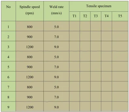
2 In this experiment, used the flamefast friction stir welding to analysis the process of experiment for multi – passes joining process, the material use in this experiment is material aluminum 5052-H3 for multi-passes joining. From this research and development for multi-passes joining to measure or identify the strength of mechanical properties, to analyze the significant value of parameter using the Taguchi Method and ANOVA to measure the significant parameter of multi – passes based on two type of parameter friction stir welding is Spindle Speed (rpm) and Weld Rate (mm/s). In this experiment for analysis the tensile strength of joining using the Universal Tensile Test Machine INSTRON 5669 to measure the strength of multi-passes joining. Tensile test it also known as tension test is probably the most fundamental type of mechanical test that can be performing on welding part to see the strength of welding area. Tensile test are simple, relatively, inexpensive, and fully standardized. By pulling on something, you will very quickly determine how the material will react to forces being applied in tension.
1.2 Problem Statement
3
1.3 Objectives
The general objective of this project is to:-
I. To optimize parameter of multi passes for friction stir welding.
II. To identify the welding strength factor of mechanical properties for multi – passes friction stir welding.
III. To determine the most significant level of parameter using the Taguchi and ANOVA method
1.4 Scope
In this research, things included and limitation of parameter for Multi – Passes for Friction Stir Welding will discussed. The area of study is optimal parameter and mechanical properties for tensile strength. The machine that will be used is Flamefast Friction Stir Welding. This is due to easy preparation of the machine. This machine also can do different parameter for spindle speed (rpm) and weld rate (mm/s) kind of process that we will use when running the experiment. The process that will involve in this experiment is parameter of Multi - Passes. These processes will use the same friction stir tool, the same parameter and same material. At the end of the process, the result of the Multi – Passes Friction Stir Welding Butt Joint that are being used in this research.
4 The material that will be used in the experiment is aluminium 5052 – H32. These materials will undergo the machining process under parameter that has been set. This research will only focus the two main things that are tensile strength and significant parameter.
Figure 1.1(a): Application Friction Stir Welding (Aerospace)
[image:20.595.109.529.163.431.2] [image:20.595.108.530.476.653.2]5 Table 1.1(a): Type of parameter
PARAMETER LEVEL OBSERVED VALUE
(Mpa)
Spindle speed (rpm) 800 900 1200 Tensile Strength
Weld Rate (mm/s) 5.0 7.0 9.0
Table 1.1(b): Experimental layout using Taguchi Method
No Spindle speed (rpm)
Weld rate (mm/s)
Tensile specimen
T1 T2 T3 T4 T5
1 800 5.0
2 900 7.0
3 1200 9.0
4 800 5.0
5 900 7.0
6 1200 9.0
7 800 5.0
8 900 7.0
[image:21.595.111.532.103.235.2] [image:21.595.105.532.307.677.2]6
CHAPTER 2
LITERATURE REVIEW
In this chapter, we will discuss literature review of this project. A literature review is based on searching, collecting, analyze, studying and write the conclusion from all debates and issues raised in the relevant body of the literature. In this project literature review will be focusing on the research of various theory and basic knowledge that are related to the friction stir welding joining. The relevant case study will be providing on this chapter as previous research are to be determined and compared with the similar.
The similar material joining part is yet to be determined after several studies on other related researches. The purpose of this chapter is, review the best type of the similar material joint for friction stir for the aluminum 5052.
2.1 Literature Review
2.1.1 Solid State Welding
In solid state welding have many type of the joining processes, type in the solid state welding is brazing, soldering, adhesive and mechanical fastening. These solid states welding commonly apply in industry aerospace, automotive, shipping build and rail.
7 friction stir, and ultrasonic, this all type for solid state is joint takes place without fusion welding at the interface of the two parts to be welding, this process no liquid or molten phase is present in the joint. The processes are automated by suing robotics, vision systems, sensors, and adaptive computer controls for the cost reduction, consistency, reliability of weld quality, and higher productivity. This solid state welding involves one or more phenomena are diffusion, pressure and relative interfacial movements.
Diffusion is the transfer of atoms across an interface causing diffusion bonding will be apply external heat improves strength of the bond between the two surfaces being joined, this heat may be generated internally by friction, electrical resistance heating and externally by induction heating. Solid state welding is a welding process in which two work pieces are joined under pressure providing an intimate contact between them and intimate contact between them and at a temperature essentially below the melting point of the parent material.
The advantages of solid state welding:
Weld bonding is free from microstructure defect.
Mechanical properties of the weld are similar to those of the parent metal. No consumable materials are required.
Dissimilar metal may be joined.
The disadvantages of solid state welding
8 This solid state welding have 6 type of solid state welding is:
Forge welding (FOW) Cold welding (CW)
Friction Stir welding (FSW) Explosive welding (EXW) Diffusion welding (DFW) Ultrasonic welding (USW)
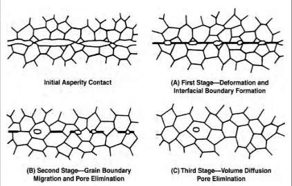
Figure 2.1(a): Three – stage mechanistic model of diffusion welding
[image:24.595.108.530.319.589.2]