(2008)
www.electrochemsci.org
Preparation of Polyaniline/Nanometer-scale Alumina Composite
by the Potential Cycling Method
Abdolmajid Bayandori Moghaddam1, *, Tayebe Nazari2
1 Department of Medicinal Chemistry, School of Pharmacy, Shahid Beheshti University of Medical Sciences, Tehran 1983963113, Iran
2 Polymer Engineering Department, Amirkabir University of Technology, P.O. Box 15875-4413, Tehran, Iran
*E-mail: [email protected]
Received: 8 April 2008 / Accepted: 29 April 2008 / Online published: 29 May 2008
A hybrid material of polyaniline/alumina nanoparticle (PAn/Al2O3 NP) was prepared with the electropolymerization of PAn film in a solution of 30 mM aniline and 100 mM sulfuric acid within dispersed Al2O3 NPs. Atomic force microscopy (AFM) procedures demonstrated the existence of different Al2O3 NPs geometrical structures. The details of PAn growth properties have been studied with the employment of potential cycling method and scanning electron microscopy (SEM). The respective resulting data are reported. In general, the Al2O3 NPs use for the construction of conductive polymers may lead to improvements in material properties for specified applications.
Keywords: Nanoparticle; Electropolymerization; Polyaniline; Atomic force microscopy; Nanotechnology
1. INTRODUCTION
Because of their many potential applications in a diverse number of fields, nanostructured materials have been the subject of many recent investigations. They have received much attention because of their novel properties, which differ from those of bulk materials. Recently, there has been great interest in controlling the shapes of materials and in finding novel properties [1-5].
nanomagnet. Furthermore, Colloidal nanoparticles towards multifunctional structures possible use for biological applications [7]. A number of investigations carried out to find applications of nanomaterials in electrochemical studies could impart strong electrocatalytic activity to some important biomolecules [8,9]. The possibility of high surface area electrodes with small dimensions has been realized in several applications: e. g., for higher performance and miniaturization of electrochemical devices [10]. Conducting polymers have this potential owing to their porous morphology [11-13].
Among various conducting polymers, polyaniline (PAn) is a unique and promising candidate for practical applications due to its good processability, environmental stability and reversible control of electrical properties by both charge-transfer doping and protonation [14,15]. Heterogeneous-conducting polymer nanocomposites have drawn the attention over the last years [16-18]. These materials exhibiting special mechanical [19,20], electronic [21], optical [22] and magnetic properties [23,24]. Such new hybrid polymer/inorganic composites cover a great range of applications including electrochromic devices, light-emitting diodes, chromatography, secondary batteries, electronic discharge protection and gas sensors. For example, PAn/carbon nanotube demonstrates high electroactivity and it consists of an excellent electrode material in plastic transistors [25]. The PAn/V2O5 may offer perspective of being utilized as a cathode for lithium secondary batteries, since it presents a relatively high conductivity and an increased specific capacity [26]. Electrochemical polymerization was also investigated to prepare nanocomposites in which colloidal ferric oxide particles have been combined with polypyrrole [27]. The electrocatalytic and sensing properties of electrochemically prepared PAn/Pt [28,29] and PAn/Pd [30] composites have been studied previously.
Electrochemical polymerization of aniline may be symbolized as having a universal stochiometry:
This has usually accepted with no experimental proof, when the potential becomes positive, diradical dications (bipolarones) are generated on the polymer chains, which allow a further PAn growth if aniline (An) is present in the solution. In this way, Stilwell and Park proposed that the PAn film grows via the following sequence of reactions [31]:
Here, (An-red)n and (An-ox)n are completely reduced and oxidized forms of PAn, respectively. The diradical dication formed on the PAn chain terminal undergoes a coupling reaction with a molecule of aniline, while accepting electrons from it. In an ideal manner, for electropolymerization of the most -conjugated polymers should take two electrons per monomer as shown in reaction (1).
xC6H5-NH2 — (C6H4-NH)x — + 2xH+ + 2xe- (1)
(An-red)n (An-ox)n + ne- (2)
However, more than two electrons are needed two actually produce these polymers, as resultant polymers end up with a further oxidized or doped state [32-34].
Stable composite materials are widely employed for various applications and coating them with conductive polymers may be useful. There is an easy control to choose advantageous materials for deposition of conductive polymers. In the present work, we synthesized the PAn films on a platinum electrode using electropolymerization of aniline. In the end, Al2O3 NPs were used for the preparation of PAn/Al2O3 NPs composite and we studied influence of these NPs in the electropolymerization of aniline.
2. EXPERIMENTAL PART
2.1. Chemical reagents
Aniline monomer (reagent grade, Merck) was kept below 0 °C. The other reagents, such as sec-butanol and sulfuric acid were prepared from Merck. 1 M and 100 mM sulfuric acid was prepared from concentrated sulfuric acidby suitable dilution.
2.2. Apparatus
Cyclic voltammetry measurements were performed using an electrochemical analyzer (µAUTOLAB TYPE III) connected to a personal computer with GPES software. The Q value for each point of the continuous CVs was obtained from the following formula:
Q = tidt
0 , Q1 = i1 t, Q2 = (i1 + i2) t, Qn =
=
=k n k 1
ik t.
Then we created the plots of E vs. Q. The measurements were carried out at ambient temperature (25 ± 2 ºC) in a conventional electrochemical cell consisting of a Pt working electrode (disk, 3.14 mm2 geometrical area exposed to the solution) assembled at the electrochemical cell, a platinum wire as the counter electrode and Ag/AgCl/KCl-sat. as reference electrode. All potentials are reported with respect to this reference electrode.
AFM-measurements were performed using a DME atomic force microscope with a Dual Scope C-21 controller and DS 95-50 scanner. Furthermore, the SEM images were recorded using a ZEISS DSM 960 instrument.
2.3. Synthesis of Al2O3 NPs
utilized. Solution was hydrolyzed by drop wise addition of sec-butanol diluted water (with the water/alkoxide mole ratio value of 3). During hydrolysis, the mixture was stirred forcefully by a magnetic stirrer. For drying of resulting gel, the mixture was heated at 90-95 °C and kept at the same temperature for 20 h. After being calcined at 1200 °C for 2 h, the sample was slowly cooled at room temperature. The treatments were performed under dry nitrogen atmosphere using standard Schlenk line method [35].
2.4. Electropolymerization of aniline
Prior to electropolymerization, surface of the Pt electrode was polished by alumina powder (0.05 µm in diameter) on a polishing cloth, followed by a thorough deionized water rinsing. The electrode was then successively sonicated in ethanol and doubly distilled water to remove the adsorbed particles.
[image:4.612.138.508.370.663.2]For electropolymerization of aniline, potentials were applied to Pt working electrode in a solution of 30 mM aniline in 100 mM sulfuric acid at 50 mV/s. To inspect the influence of Al2O3 NPs on the electropolymerization of aniline, this process was monitored on a conventional substrate electrode but in dispersed Al2O3 presence (0.03 g in 30 mL) in the solution and then sonicated to obtain a uniform dispersion.
Figure 1. (a-c) AFM images of Al2O3 NPs, (d) obtained image profile for selected direction by arrow from Figure 1(c).
(a)
(b)
(c)
38 nm
188 nm
Distance/nm
H
ei
gh
t/n
m
E/V
3. RESULTS AND DISCUSSION
3.1. AFM measurements of synthesized Al2O3 NPs
[image:5.612.133.435.211.673.2]For the structure investigation of synthesized nanoparticles the utilization of atomic force microscopy (AFM) was considered. Figure 1(a-c) present AFM images of Al2O3 NPs. In addition, Figure 1(d) demonstrates the related image profile for selected direction by arrow from Figure 1(c). This profile displays a nanoparticle diameter in top and bottom for selected points in AFM image with 38.0 and 188.0 nm, respectively.
Figure 2. (a) (a) The growth of PAn film by cycling potential (30 cycles) in a solution of 30 mM of aniline in 100 mM of sulfuric acid at 50 mV/s, (b) charge passed through the electrochemical cell (Q) vs. the time plot, data were obtained for 30 cycles.
I/
A
(a)
-4.E-05 -3.E-05 -2.E-05 -1.E-05 0.E+00 1.E-05 2.E-05 3.E-05
0 0.2 0.4 0.6 0.8 1
E/V
I/
A
(a)
y = 5E-12x2 + 9E-07x + 0.0001
0.0E+00 2.0E-04 4.0E-04 6.0E-04 8.0E-04 1.0E-03 1.2E-03 1.4E-03 1.6E-03
0 200 400 600 800 1000 1200
Q
(C
)
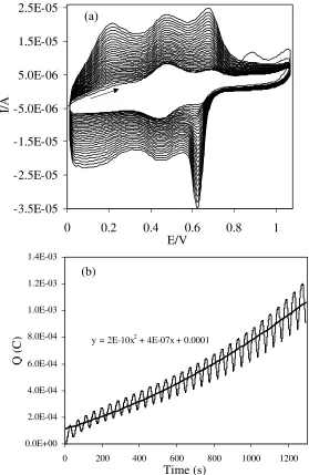
Figure 3. (a) The growth of PAn film by cycling potential (30 cycles) in a solution of 30 mM of aniline in 100 mM of sulfuric acid with Al2O3 NPs dispersed into the electrolyte solution at 50 mV/s, (b) charge passed through the electrochemical cell (Q) vs. the time plot, data were obtained for 30 cycles.
3.2. PAn growth in the absence and presence of the Al2O3 NPs
The growth of PAn film is dependent upon the anion that is present in supporting electrolyte solution during the electropolymerization [36]. This was given details before as a result of the propensity of some anions, e.g. HSO4− and Cl− to be adsorbed specially on the working electrode surface. Other anions such as ClO4− do not adsorb on the electrode surface. The electropolymerization in the presence of first type anions is faster than with the second one [37-40].
y = 2E-10x2 + 4E-07x + 0.0001
0.0E+00 2.0E-04 4.0E-04 6.0E-04 8.0E-04 1.0E-03 1.2E-03 1.4E-03
0 200 400 600 800 1000 1200
Q
(C
)
Time (s) (b)
-3.5E-05 -2.5E-05 -1.5E-05 -5.0E-06 5.0E-06 1.5E-05 2.5E-05
0 0.2 0.4 0.6 0.8 1
E/V
I/
[image:6.612.150.429.80.509.2]Figure 2(a) shows the cyclic voltammograms (CVs) which were recorded during continuous potential cycles in a solution of 30 mM aniline in 100 mM sulfuric acid on a platinum (Pt) substrate electrode. This way consists of the conventional synthesis with voltammogram shapes being well-defined as assigned in previous reports [31,41]. In addition, Figure 2(b) shows charge passed through the electrochemical cell (Q) for voltammograms versus the polymerization time.
The preparation of inorganic particle/conductive polymer composites has received great attention, on the grounds that such composites have potentials for many useful properties [26,27]. Therefore, Figure 3(a) shows the cyclic voltammograms simultaneously recorded during continuous potential cycles in a solution of 30 mM aniline in 100 mM sulfuric acid in the presence of Al2O3 NPs, dispersed in electrolyte solution. Moreover, Figure 3(b) presents charge passed through the electrochemical cell (Q) for voltammograms of Figure 3(a) versus the polymerization time.
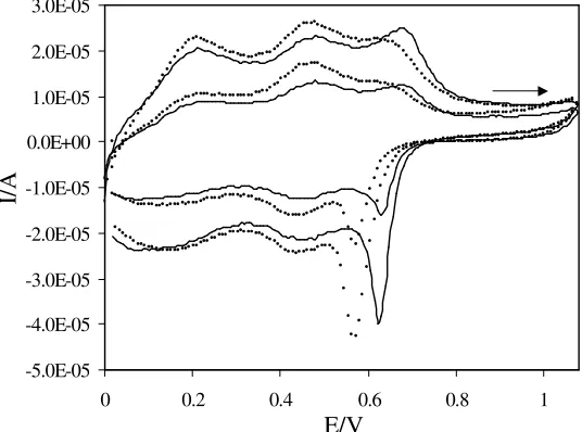
[image:7.612.173.441.402.601.2]Here it is important to mention that addition of Al2O3 NPs into electrolyte solution affects the electropolymerization process. For this reason, a certain quantity of Al2O3 (0.03 g) was dispersed in the electrolyte solution (30 mL) and then sonicated to obtain a uniform dispersion. After comparing Figures 2 and 3, influence of Al2O3 NPs in the electropolymerization of aniline can be observable. Third oxidation peak appears as stronger oxidation peak. This marks that Al2O3 NPs existence results in the happening of a rigorous oxidation process that plays an important role in the subsequent electropolymerization process and polymer growth. This phenomenon became more evident from Figure 4 that presents the 15th and 30th comparative cycle numbers during the electropolymerization of aniline in the absence and presence of Al2O3 NPs in electrolyte solution.
Figure 4. 15th and 30th cyclic voltammograms during the PAn growth by cycling potential at 50 mV/s from a solution of 30 mM of aniline and 100 mM of sulfuric acid (dotted line) and 30 mM of aniline and 100 mM of sulfuric acid with dispersed Al2O3 NPs (solid line).
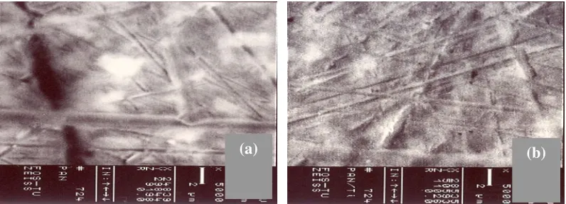
Figure 5a shows the SEM image of electrodeposited PAn film on the Pt electrode. As can be seen from this image, the polymer film has fractures. This failure, which is the main one for
-5.0E-05 -4.0E-05 -3.0E-05 -2.0E-05 -1.0E-05 0.0E+00 1.0E-05 2.0E-05 3.0E-05
0 0.2 0.4 0.6 0.8 1
E/V
I/
electrodeposition on the Pt substrate, is accompanied by a polymer breakdown. Figure 5b shows the SEM image of PAn film electrodeposited on Pt substrate in the presence of Al2O3 NPs. Compare the morphology of PAn grown in the absence and presence of dispersed Al2O3 NPs in solution shown that two SEM images are different. One from the electropolymerization with dispersed Al2O3 NPs in solution is much smoother than electropolymerization in the absence of Al2O3 NPs. In accordance with Figure 5b no fractures were observed on PAn film. In fact, such structure has been produced from Al2O3 NPs attendance during the electropolymerization process and film substrate is a result of polymer growth and special structure of Al2O3 NPs. So, the film can be presents a better physical stability.
Figure 5. SEM images of PAn grown under the conditions used for (a) Figure 2 (a) and (b) Figure 3 (a).
4. CONCLUSIONS
PAn/Al2O3 NPs composite were synthesized by electropolymerization on the platinum substrate electrode. The results indicated that Al2O3 NPs presence can affect the electropolymerization process. This effect happens when Al2O3 acts as incorporating agent. The PAn/Al2O3 NPs composite formation without any film fractures were. It is simple to control the composite structure using various types and shapes of metal oxide nanomaterials. Since composites made from metal oxide nanomaterials display essential stability and polymer film growth is efficiently stable, this approach can be productively employed for practical purposes.
References
1. E. O. Dare, Turk. J. Chem. 30 (2006) 585.
2. Z. W. Pan, Z. R. Dai, Z. L. Wang, Science 291 (2001) 1947.
3. M. Akarsu, M. Asiturk, F. Sayikan, N. Kiraz, E. Arpac, H. Sayilkan,Turk. J. Chem. 30 (2006) 333. 4. N. Kasapoglu, A. Baykal, M. S. Toprak, Y. Koseoglu, H. Bayrakdar, Turk. J. Chem. 31 (2007)
659.
5. G. H. Woehrle, J. E. Hutchison, S. Ozkar, R. G. Finke, Turk. J. Chem. 30 (2006) 1.
6. D. L. Klein, R. Roth, A. K. L. Lim, A. P. Alivisatos, P. L. McEuen, Nature 389 (1997) 699. 7. T. Pellegrino, S. Kudera, T. Liedl, A. M. Javier, L. Manna, W. J. Parak, Small 1 (2005) 49.
8. A. Bayandori Moghaddam, M. Kazemzad, M. R. Nabid, H. H. Dabaghi, Int. J. Electrochem. Sci. 3 (2008) 291.
9. P. Xiao, W. Wu, J. Yu, F. Zhao, Int. J. Electrochem. Sci. 2 (2006) 149. 10. K. S. V. Santhanam, N. Gupta, Trends Polym. Sci. 1 (1993) 284.
11. P. Novok, K. Muller, K. S. V. Santhanam, O. Hass, Chem. Rev. 97 (1997) 207. 12. C. Arbizzani, M. Catellani, M. Mastragostino, Electrochim. Acta 40 (1995) 1871. 13. C. Arbizzani, M. Mastragostino, M. Meneghello, Electrochim. Acta 41 (1996) 21. 14. G. Premamoy, K. S. Samir, C. Amit, Eur. Polym. J. 35 (1999) 699.
15. B. A. Deore, I. Yu, M. S. Freund, J. Am. Chem. Soc. 126 (2004) 52.
16. S. W. Phang, M. Tadokoro, J. Watanabe, N. Kuramoto, Curr. Appl. Phys. 8 (2008) 391. 17. T. A. Kerr, H. Wu, L. F. Nazar, Chem. Mater. 8 (1996) 2005.
18. Y.-C. Liu, J.-M. Huang, C.-E. Tsai, T. C. Chuang, C.-C. Wang, Chem. Phys. Lett. 387 (2004) 155. 19. W. Jia, R. Tchoudakov, E. Segal, M. Narkis, A. Siegmann, J. Appl. Polym. Sci. 91 (2003) 1329. 20. M. S. Cho, H. J. Choi, W. S. Ahn, Langmuir 20 (2004) 202.
21. P. R. Somani, R. Marimuthu, U. P. Mulik, S. R. Sainkar, D. P. Amalnerkar, Synth. Met. 106 (1999) 45.
22. S. Kuwabata, N. Takahashi, S. Hirao, H. Yoneyama, Chem. Mater. 5(1993) 437.
23. H. L. Frisch, H. Song, J. Ma, M. Rafailovich, S. Zhu, N. L. Yang, X. J. Yan, Phys. Chem. B 105 (2001) 11901.
24. Z. Zhang, M. Wan, Synth. Met. 132 (2003) 205.
25. M. Lefenfeld, G. Blanchet, J. A. Rogers, Adv. Mater. 15 (2003) 1188.
26. H. M. Ferreira, V. Zucolotto, F. C. Nart, R. M. Torresi, O. N. Jr. Oliveira, Chem. Mater. 16 (2004) 2293.
27. R. Gangopadhyay, A. De, Eur. Polym. J. 35 (1999) 1985. 28. W.-H. Kao, T. Kuwana, J. Am. Chem. Soc. 106 (1984) 473.
29. J. M. Kinyanjui, N. R. Wijeratne, J. Hanks, D. W. Hatchett, Electrochim. Acta 51 (2006) 2825. 30. Y. M. Maksimov, E. A. Kolyadko, A.V. Shishlova, B. I. Podlovchnko, Russ. J. Electrochem. 37
(2001) 777.
31. D. E. Stilwell, S.-M. Park, J. Electrochem. Soc. 135 (1988) 2254. 32. S.-Y. Cui, S.-M. Park, Synth. Met. 105 (1999) 91.
33. B. J. Johnson, S.-M. Park, J. Electrochem. Soc. 143 (1996) 1269. 34. Y.-B. Shim, S.-M. Park, Synth. Met. 29 (1989) E169.
35. D. F. Shriver, M. A. Drezdzon, “The Manipulation of Air-Sensitive Compounds” 2nd edn, Wiley, New York, 1986.
36. L. Duic, Z. Mandic, F. Kovacicek, J. Polym. Sci. A 32 (1994) 105. 37. V. Brandl, R. Holze, Ber. Bunsengez. Phys. Chem. 101 (1997) 251. 38. H. Angerstein-Kozlowska, B. Conway, J. Electroanal. Chem. 95 (1979) 1. 39. B. Conway, D. Novak, J. Electroanal. Chem. 99 (1979) 133.
40. B. Conway, D. Novak, J. Chem. Soc., Faraday Trans.75 (1979) 2454. 41. D. E. Stilwell, S.-M. Park, J. Electrochem. Soc. 135 (1988)2491.