COMPARATIVE EVALUATION OF SHEAR BOND
STRENGTH OF HEAT POLYMERISED ACRYLIC RESIN
TO SURFACE TREATED COBALT-CHROMIUM AND
TITANIUM ALLOYS - AN IN VITRO STUDY
Dissertation Submitted to
THE TAMILNADU DR. M.G.R. MEDICAL UNIVERSITY
In partial fulfillment for the Degree of
MASTER OF DENTAL SURGERY
BRANCH I
PROSTHODONTICS AND CROWN & BRIDGE
ACKNOWLEDGEMENT
First of all, I would like to thank Almighty God for giving me the strength,
courage and confidence to overcome all hurdles and finish this arduous job.
This dissertation is the result of work with immense support from many
people and it is my pleasure to take this opportunity to express my gratitude to all
of them.
I would be failing in my duty if I do not adequately express my deep sense
of gratitude and my sincere thanks to Dr. N. S. Azhagarasan, M.D.S., Professor
and Head of the Department, Department of Prosthodontics and Crown
&Bridge, Ragas Dental College and Hospital, Chennai, for his exceptional
guidance, tremendous encouragement and well timed suggestions throughout my
postgraduate programme. I would like to profoundly thank him for giving an
ultimate sculpt to this study.
I wish to express my gratitude to Dr. S Ramachandran, M.D.S.,
Principal, Ragas Dental College, Chennai for his encouragement and support
throughout my post graduate course. I also thank him for permitting me to make
use of the amenities in the institution.
I would like to express my real sense of respect, gratitude and thanks to my
Guide, Dr. K. Chitra Shankar, M.D.S., Professor for her guidance, constant
support and encouragement extended to me during this study. Her patience and
perseverance benefited me in every facet of my study and I thoroughly enjoyed
me to develop an understanding of the subject from the concept to the conclusion.
Her guidance and supervision helped me to bring the best out of me in this study.
The timely help and encouragement rendered by her had been enormously helpful
throughout my study.
I would also like to thank Dr. K. Madhusudan, M.D.S.,
Dr.S. Jayakrishnakumar, M.D.S., Dr. Manoj Rajan, M.D.S. and
Dr. Saket Miglani, M.D.S., for their valuable suggestions and support given
throughout my study.
My sincere thanks to Dr. Manikandan, M.D.S., Dr.R. Hariharan, M.D.S.,
Dr.M.Saravana Kumar, M.D.S., Dr.Vallabh Mahadevan, M.D.S.,
Dr.Sabarinathan, M.D.S., Dr.Divya Krishnan, M.D.S., for their support during
this study.
I would like to thank Professor Dr.N. Kalyana Krishnan, Sree Chitra
Tirunal Institute for Medical Sciences And Technology, Thiruvananthapuram, for
helping me in thermocycling procedure.
I would like to convey my sincere thanks to Professor Mr.N.Karthikeyan,
and Mr.D.Balamurugan, Department of Mechanical Engineering, Central
Institute of Plastic Engineering and Technology, Chennai, for their help and
support throughout the study.
I would like to convey my gratitude to Professor Mr.Srinivasan and
Mr.Babu, Department of Mechanical Engineering, Anna University, Guindy,
I would like to thank Mr.Sakthinathan, Assistant Professor and
Mr.Vetrivel, Technical Assistant, Department of Manufacturing Engineering for
helping me in the Surface Profilometric analysis.
My thanks to Ms.S.Deepa, Statistician, Department of Oral Pathology,
Ragas Dental College and Hospital, Chennai, for her valuable help with the
statistical work for this study.
It would not be justifiable on my part if I do not acknowledge the help of
my fellow colleagues, my seniors, juniors and friends for their constant
encouragement and continued support throughout my post graduate course.
Last but not the least, even though words would not do much justice, I
would like to specially thank my husband, parents, my brother and my daughter
CONTENTS
Title Page No
1.
INTRODUCTION 12.
REVIEW OF LITERATURE 93.
MATERIALS AND METHODS 214.
RESULTS 435.
DISCUSSION 496.
CONCLUSION 647.
SUMMARY 70LIST OF TABLES
Table No. Title Page No.
1 Basic values and Mean value of shear bond strength 45
in Mpa for acrylised samples of Group Ia.
2 Basic values and Mean value of shear bond strength 45
in Mpa for acrylised samples of Group Ib.
3 Basic values and Mean value of shear bond strength 46
in Mpa for acrylised samples of Group IIa.
4 Basic values and Mean value of shear bond strength 46
in Mpa for acrylised samples of Group IIb.
5 Comparison of Mean shear bond strengths 47
of Group Ia with Group Ib
6 Comparison of Mean shear bond strengths 47
of Group IIa with Group IIb
7 Comparison of Mean shear bond strengths 48
of Group Ia with Group IIa
8 Comparison of Mean shear bond strengths 48
ANNEXURE
LIST OF FIGURES
Fig.No. Title
Fig 1a: Line diagram showing assembled custom made mold
Fig 1b-f: Line diagram of individual custom made mold parts
Fig 2: Custom-made mold
Fig 3: Petroleum jelly
Fig 4: Pattern resin
Fig 5a: Inlay wax
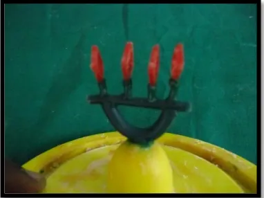
Fig 5b: Preformed mesh pattern
Fig 6: Sprue wax
Fig 7: Surfactant spray
Fig 8: Silicon casting ring
Fig 9: Phosphate bonded investment
Fig 10: Alumina and Magnesia based investment
Fig 11: Investment liquid
Fig 12: Co-Cr alloy
Fig 13: Ti-6Al-4V alloy
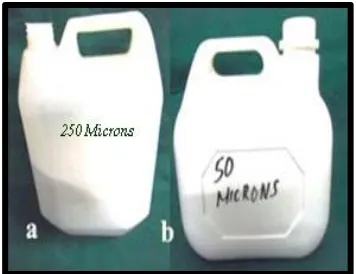
Fig 14a: Aluminium oxide powder 250µm
Fig 14b: Aluminium oxide powder 50µm
Fig 15: Modelling wax
Fig 17a: Separating medium
Fig 17b: Heat cure acrylic resin
Fig 18: Alloy Primer
Fig 19a: Separating discs
Fig 19b: Rubber polishing wheel
Fig 20: Wax solvent
Fig 21a: Sandpaper of different grit sizes
Fig 21b: Pumice
Fig 22: Distilled water
Fig 23: PKT instrument
Fig 24a: Stainless steel metal scale
Fig 24b: Wax caliper
Fig 24c: Metal caliper
Fig 25a: Porcelain cup
Fig 25b: Measuring jar
Fig 26a: Wax knife
Fig 26b: Wax carver
Fig 26c: Stainless steel spatula
Fig 27: Rubber bowl
Fig 28a: Metal trimmers and disc mandrel
Fig 28b: Acrylic trimmers
Fig 28c: Sandpaper mandrel
Fig 29: Denture flask and dental clamp
Fig 31: Burnout furnace
Fig 32: Crucible
Fig 33: Induction casting machine
Fig 34: Casting machine for titanium
Fig 35: Sandblaster
Fig 36: Alloy grinder
Fig 37: Dental lathe
Fig 38: Acryliser
Fig 39: Steam cleanser
Fig 40: Plastic containers
Fig 41: Incubator
Fig 42: Thermocycler
Fig 43: Universal testing machine
Fig 44: Surface Profilometer
Fig 45: Scanning Electron Microscope
Fig 46a,b: Schematic diagram showing sample pattern dimensions
Fig 46c: Patterns with a space in the centre
Fig 46d: Preformed mesh patterns
Fig 46e: Finished sample patterns
Fig 47: Sprue attached patterns
Fig 48: Investment mold
Fig 49: Retrieved casting
Fig 50: Finished Co-Cr alloy samples
Fig 52: Finished Ti-6Al-4V alloy samples
Fig 53a: Line diagram showing cylindrical acrylic extension dimensions
Fig 53b: Line diagram showing waxed-up alloy sample
Fig 53c: Waxed up alloy samples
Fig 54: Invested waxed up samples
Fig 55: Denture flask carrying the cylindrical mold spaces for acrylic and alloy samples in the flask base
Fig 56a: Air abraded alloy samples
Fig 56b: Alloy primer application
Fig 57: Deflasked samples
Fig 58: Finished samples
Fig 59a: Samples in the separate, labeled containers
Fig 59b: Samples in the incubator
Fig 60: Samples in the thermocycler
Fig 61: Sample fixed in the sample fixture of universal testing machine
Fig 62: Tested samples
LIST OF GRAPHS
Graph No: Title
Graph 1 Basic values of shear bond strength (in Mpa) for Group Ia
Graph 2 Basic values of shear bond strength (in Mpa) for Group Ib
Graph 3 Basic values of shear bond strength (in Mpa) for Group IIa
Graph 4 Basic values of shear bond strength (in Mpa) for Group IIb
Graph 5 Comparison of mean shear bond strength values of
Group Ia, Ib, IIa and IIb
Graph 6 Comparison of shear bond strength values of Group Ia with Group Ib
Graph 7 Comparison of mean shear bond strength values of Group Ia with
Group Ib
Graph 8 Comparison of shear bond strength values of Group IIa with Group IIb
Graph 9 Comparison of mean shear bond strength values of Group IIa with
Group IIb
Graph 10 Comparison of shear bond strength values of Group Ia with Group IIa
Graph 11 Comparison of mean shear bond strength values of Group Ia with
Group IIa
Graph 12 Comparison of shear bond strength values of Group Ib with Group IIb
Graph 13 Comparison of mean shear bond strength values of Group Ib with
LIST OF SURFACE PROFILOMETRY PHOTOMICROGRAPHS
Fig.No. Title
Fig 64: 3-D image of Group Ia
Fig 65: Advanced 3-D image of Group Ia
Fig 66: 3-D image of Group Ib
Fig 67: Advanced 3-D image of Group Ib
Fig 68: 3-D image of Group IIa
Fig 69: Advanced 3-D image of Group IIa
Fig 70: 3-D image of Group IIb
LIST OF SEM PHOTOMICROGRAPHS
Fig No. Title
Fig 72: SEM photomicrograph of Group Ia pretest SEM under 10x
Fig 73: SEM photomicrograph of Group Ib pretest SEM under 10x
Fig 74: SEM photomicrograph of Group Ia pretest SEM under 500x
Fig 75: SEM photomicrograph of Group Ib pretest SEM under 500x
Fig 76: SEM photomicrograph of Group IIa pretest SEM under 10x
Fig 77: SEM photomicrograph of Group IIb pretest SEM under 10x
Fig 78: SEM photomicrograph of Group IIa pretest SEM under 500x
Fig 79: SEM photomicrograph of Group IIb pretest SEM under 500x
Fig 80: SEM photomicrograph of Group Ia fractured alloy surface under 10x
Fig 81: SEM photomicrograph of Group Ia fractured alloy surface under 250x
Fig 82: SEM photomicrograph of Group Ia fractured alloy surface under 500x
Fig 83: SEM photomicrograph of Group Ia fractured alloy surface under 1000x
Fig 84: SEM photomicrograph of Group Ia fractured acrylic surface under 10x
Fig 85: SEM photomicrograph of Group Ia fractured acrylic surface under 250x
Fig 86: SEM photomicrograph of Group Ia fractured acrylic surface under 500x
Fig 87: SEM photomicrograph of Group Ia fractured acrylic surface under 1000x
Fig 88: SEM photomicrograph of Group Ib fractured alloy surface under 10x
Fig 89: SEM photomicrograph of Group Ib fractured alloy surface under 250x
Fig 90: SEM photomicrograph of Group Ib fractured alloy surface under 500x
Fig 92: SEM photomicrograph of Group Ib fractured acrylic surface under 10x
Fig 93: SEM photomicrograph of Group Ib fractured acrylic surface under 250x
Fig 94: SEM photomicrograph of Group Ib fractured acrylic surface under 500x
Fig 95: SEM photomicrograph of Group Ib fractured acrylic surface under 1000x
Fig 96: SEM photomicrograph of Group IIa fractured alloy surface under 10x
Fig 97: SEM photomicrograph of Group IIa fractured alloy surface under 250x
Fig 98: SEM photomicrograph of Group IIa fractured alloy surface under 500x
Fig 99: SEM photomicrograph of Group IIa fractured alloy surface under 1000x
Fig 100: SEM photomicrograph of Group IIa fractured acrylic surface under 10x
Fig 101: SEM photomicrograph of Group IIa fractured acrylic surface under 250x
Fig 102: SEM photomicrograph of Group IIa fractured acrylic surface under 500x
Fig 103: SEM photomicrograph of Group IIa fractured acrylic surface under 1000x
Fig 104: SEM photomicrograph of Group IIb fractured alloy surface under 10x
Fig 105: SEM photomicrograph of Group IIb fractured alloy surface under 250x
Fig 106: SEM photomicrograph of Group IIb fractured alloy surface under 500x
Fig 107: SEM photomicrograph of Group IIb fractured alloy surface under 1000x
Fig 108: SEM photomicrograph of Group IIb fractured acrylic surface under 10x
Fig 109: SEM photomicrograph of Group IIb fractured acrylic surface under 250x
Fig 110: SEM photomicrograph of Group IIb fractured acrylic surface under 500x
1
INTRODUCTION
In removable prosthodontics, partial dentures are commonly fabricated
with acrylic resin and metal alloys.18,48,32 The choice of alloy for the removable
partial denture (RPD) framework is based upon criteria, such that, it should be
non-toxic, non allergenic, corrosion resistant, easy to use, relatively
inexpensive and have adequate strength2,6.
Traditionally noble metal alloys were used for the fabrication of RPD
frameworks. Base metal alloys were introduced as an alternative to noble
alloys. Co-Cr alloys are the most common base metal alloy used for
removable prosthesis that incorporates metal components. Co-Cr alloys are
relatively inexpensive and are approximately twice as rigid as Au alloys, but
may contain elements that cause sensitivity or allergic reactions in some
patients. Additionally laboratory manipulation of these alloys is difficult.2,6,21
Recently, titanium and its alloys have been increasingly used in clinical
practice for RPD frameworks. Despite drawbacks such as lengthy burn out,
difficulties in machinability, casting, polishing, inferior flexibility and higher
initial costs, advantages such as its excellent corrosion resistance,
biocompatibility, strength and ductility, render titanium as an ideal biomaterial
for removable partial denture.21,24,28,37,38,41,45
Heat polymerized acrylic resin is generally utilized for attaching
2
advantages which include, its similarity in appearance to oral tissues and its
ease of manipulation, but it also has disadvantages such as poor mechanical
properties and residual monomer that may cause allergic and hypersensitive
reactions.2,6
Durability of the removable partial denture is dependent on the strong
adhesion between the metal framework and acrylic resin.4,18,21 However the
junction between the metal alloy and acrylic resin is an area of clinical
concern. Microleakage at this junction may result in resin discolouration, fluid
percolation, microbial proliferation and deterioration of contact between the
metal alloy and acrylic resin. RPD failures are usually linked to this
interface.34,44
In the oral environment, the bond between the acrylic resin and metal
must withstand continual exposure to occlusal forces, saliva and temperature
variations occurring during ingestion of hot and cold food and drink. The
difference in the coefficient of thermal expansion between the metal and
acrylic resin is considerable. The lack of adhesion and the difference in the
coefficient of thermal expansion together places severe demands on the
metal/acrylic interface.18,32,44 The absence of bonding between the unprepared
metal alloy and acrylic resin interface is well documented.44,61 Various
methods for alloy surface preparations have been suggested to achieve an
improved bond.29 Metal surface treatments have been classified as mechanical
3
micromechanical treatment of the alloy. Chemical bonding may be interfacial
or adhesive in nature.44
The macromechanical retention for a denture base resin is usually
provided by the framework design in the prosthesis by using beads, posts,
bars, lattice and mesh.32,34,37,44,48,61 Previous studies have compared the various
macromechanical retention designs. Although the open lattice design provided
higher retention to the denture base resin, it was more susceptible to
permanent deformation. The mesh design has been suggested as suitable for
most situations with buccal and lingual reinforcement of mesh retention
design.8,29 Hence this mesh design was incorporated as the macro-mechanical
retention design in this study. The major disadvantage of macromechanical
retention between the denture base resin and metal framework is poor
marginal sealing which permits microleakage and its sequelae.32,34,37,44,48,61
With a view to minimize these problems, micromechanical retention
has been suggested. Micromechanical retention increases the surface area and
enhances the wettability by increasing surface-free energy. Micromechanical
retention includes electrolytic etching, gel (acid) etching and air abrasion.44
The retentive strength of acrylic resin to acid-etched frameworks has also been
reported as an alternative to mechanical retention.29 Although, electrochemical
etching and acid etching significantly improve in bond strength they are
associated with expensive equipment, technique sensitivity and harmful
4
by increasing the surface area.7 Studies have suggested that air abrasion as one
of the mechanisms of consistently improving the bond strength without the
above drawbacks.15,18,44 Hence air abrasion was chosen to provide
micromechanical bond in this study.
Chemical bonding between the metal framework and the denture base
resin is also important. Poor chemical bonding in this area is a significant
problem, which often results in adhesive failure.4,6,37,44 Chemical bonding was
developed as an alternative to etching systems.44 Chemical bonding systems
reduce the gap at the resin/metal interface thus minimizing microleakage.
Kourtis classified chemical bonding systems into three main groups according
to their mechanism of adhesion, namely, silica coating, tin plating and bonding
agents with active acrylate monomers.29
Silica coating procedures produce an intermediate layer containing
silicon dioxide on the metal surface providing sufficient bonding to acrylic
resin. Several studies have demonstrated that silica coated metal exhibited
significantly higher bond strength than electro-etched metal.29,30,31,32 Available
silica coating systems like Rocatec, Silicoater MD require expensive
equipment and strong potentially corrosive chemicals.4,29 Tin plating is
relatively easily performed with consistent results, although lower bond
strengths have been reported for base metal alloy.44 Adhesive primers
containing functional methacrylate monomers have been successfully
5
The availability of adhesive primers that are capable of chemical bonding to
dental base metal alloys has simplified the surface preparation procedure.21
The application of a 4-methacryloxyethyl trimellitate anhydride (4-META)
has been recommended for bonding Co-Cr alloys.6,16,18,21,28 Recently primers
containing 10- methacryloxydecyl dihydrogen phosphate (MDP) have been
developed to enhance the bonding of resin to base metal alloys.6,18 The
6-(4-vinylbenzyl-n-propyl) amino-1,3,5-triazine-2,4-dithione (VBATDT) has
been found to be an effective primer when used on noble metals.6 Recent
studies have reported that a primer containing both MDP and VBATDT, is
effective in achieving the improved bonding between the heat polymerized
resin and base metal alloys such as Co-Cr alloy and cp titanium.6,18,21,28 Hence
this adhesive primer was used for chemical bonding in this study.
Water storage and thermocycling influence the properties of the
material used in the prosthesis thereby simulating one of the factors in the oral
environment. Thermocycling procedures represent the various temperature
changes to which the prosthesis subjected during use. The loss of bond
strength due to water storage and thermocycling has been well
documented.18,20,32,50
Surface treatments produce alterations in the surface texture of the
alloy. Alteration of surface profile may affect the contact surface area of the
metal which is available for both mechanical and chemical bonding. Surface
6
scanning electron microscopy respectively, aids in better visualization of the
treated surfaces and failure patterns. The possible influence of an increase in
surface area subjected to air abrasion with different grit sizes as measured by
3-D surface profilometry, on the bond strength has been quoted in a study7.
Other studies have employed pre and post testing SEM analyses to
qualitatively assess the surface topography and understand the modes of
failure.18,37,61 In these studies various grit sizes for air abrasion and chemical
bonding systems, have been compared. Combined 3-D surface profilometric
and scanning electron microscopic comparative analyses of air abraded alloy
surfaces with alloy surfaces subjected to air abrasion followed by Alloy
Primer application are sparse.
Many studies have evaluated the adhesion of composite veneering to
titanium and its alloys with adhesive primers and have reported higher bond
strength values as applicable to fixed prosthodontics. However studies
evaluating the bond between Ti alloy and denture base resin as applicable in
removable prosthodontics are relatively few.21 Also comparative studies on the
bond strength of denture base resin to Co-Cr alloy and Ti-6Al-4V alloy are
still fewer. In these studies, the alloy samples have a smooth, flat surface
design subjected to different surface treatments.18,21,28,37 Aging and
thermocycling parameters have not always been included in these study
design. Studies which comparatively evaluate the shear bond strength between
7
mesh design subjected to different surface treatments followed by aging and
thermocycling procedures prior to testing are lacking.
In light of the above considerations, the aim of the present in-vitro
study was to comparatively evaluate the shear bond strength of heat
polymerized acrylic resin to Co-Cr and Ti-6Al-4V alloys with two different
surface treatments, namely, air abrasion and air abrasion followed by Alloy
Primer application after being subjected to aging and thermocycling and
correlated with quantitative 3-D surface texture analyses of treated alloy
samples along with pre and post testing SEM analyses.
The objectives of the present study included the following:
1. To evaluate the shear bond strength of heat polymerized acrylic resin
to Co-Cr alloy samples treated with two different surface treatments,
namely, air abrasion and air abrasion followed by Alloy Primer
application after aging and thermocycling.(Group Ia and Group Ib)
2. To evaluate the shear bond strength of heat polymerized acrylic resin
to Ti-6Al-4V alloy samples treated with two different surface
treatments, namely, air abrasion and air abrasion followed by Alloy
Primer application after aging and thermocycling.(Group IIa and
Group IIb)
3. To compare the shear bond strength values of heat polymerized acrylic
resin to Co-Cr alloy samples treated with two different surface
8
4. To compare the shear bond strength values of heat polymerized acrylic
resin to Ti-6Al-4V alloy samples treated with two different surface
treatments after aging and thermocycling. (Group IIa with Group IIb)
5. To compare the shear bond strength values of heat polymerized acrylic
resin to Co-Cr alloy and Ti-6Al-4V alloy samples treated with air
abrasion after aging and thermocycling. (Group Ia with Group IIa)
6. To compare the shear bond strength values of heat polymerized acrylic
resin to Co-Cr alloy and Ti-6Al-4V alloy samples treated with air
abrasion followed by Alloy Primer application after aging and
thermocycling. (Group Ib with Group IIb)
7. To quantitatively evaluate the surface texture of one representative test
sample each of Co-Cr and Ti-6Al-4V alloys subjected to two different
surface treatments respectively, prior to acrylisation by 3-D surface
profilometry.
8. To qualitatively evaluate the surface topography of one representative
test sample each of Co-Cr and Ti-6Al-4V alloys subjected to two
different surface treatments respectively, prior to acrylisation by
scanning electron microscopy (SEM analysis).
9. To qualitatively evaluate the mode of failure of the one representative
acrylised and tested samples of the four test groups by scanning
9
REVIEW OF LITERATURE
Lamstein A et al (1956)25 presented experimental evidence to confirm
the existence of marginal seepage and percolation under acrylic resins of the
gold acrylic resin veneer crowns, made with and without window perforation.
They found that crowns with perforations exhibited more marginal seepage.
Dunny AJ, King GE et al (1975)13 tested the effect of nine acrylic
retention designs on shear strength of acrylic resin attachment to
the partial denture framework in anterior edentulous spaces. Framework
designs that allowed a greater bulk of acrylic resin projecting through
openings in retention design, offered strong retention.
Livaditis J et al (1982)26 described a technique for the retentive
mechanism for the resin bonded retainers and described about the
development and clinical application of electrolytic etching process. They
described a technique of etching the inner side of cast fixed partial denture
which is bonded to acid etching enamel surface.
Crim GA, Swartz ML et al (1985)11 compared the effectiveness of
four thermocycling techniques with tracers. Two thermocycling systems with
different dwell times were used. They found no significant difference among
the four thermocycling techniques and all demonstrated leakage.
Tanaka T et al (1986)51 devised a method of treating the interior
10
and Co-Cr alloys. They concluded that sufficient bonding strength and
adhesion was obtained for the Co-Cr alloy by merely sandblasting with
alumina and ultrasonic wave polishing even after thermocycling.
Zurasky EL et al (1987)61 compared and concluded that the retentive
bond strength of an acid etched base metal to acrylic resin was 3.5 times
greater than that obtained with bead retention.
Brown DT et al (1987)8 compared the fatigue strength of acrylic
retention designs including mesh, reinforced mesh design, lattice and smooth
plate. They concluded that mesh retention as suitable for most situations and
with buccal and lingual reinforcement of mesh design.
Yamauchi M et al (1988)56 revealed some casting defects of pure
titanium and follow-up observations of patients with these dentures. Casting in
the mesh type wax pattern less than 0.35mm thick produced more incomplete
form of mesh and suggested a minimum mesh thickness of 0.7mm.
Jacobson TE et al (1988)16 compared the bond strength of a
conventional polymethylmethacrylate acrylic denture base with an acrylic
resin containing 4-META to Co-Cr metal alloy by using various designs
representative of clinical situations. They found higher bond strength between
the 4-META resin and the alloy.
May KB et al (1993)30 compared the shear bond strength between
11
abrasive and with 110µm alumina air abrasive plus silicoating. They
concluded that surface treatment of titanium treated with 110µm alumina air
abrasive plus silane coating increased the bond strength of titanium to
polymethylmethacrylate.
Barclay CW et al (1994)5 compared the tensile and shear bond
strengths of two self-cure acrylic resins to cobalt-chromium alloy (Co-Cr)
samples, prepared with six surface finishes. The strongest mean tensile bond
strength was recorded between the 4-Meta incorporated acrylic resin and
Silicoated cobalt-chromium alloy.
Kononen M et al (1995)22 published a clinical report of treating a
partially edentulous patient, who was hypersensitive to other metals with a
titanium cast partial denture with a two year follow up without complications.
They concluded that titanium was a relatively newer and alternative material
for removable partial denture frameworks.
May KB et al (1995)31 compared the shear bond strength between the
polymethylmethacrylate and titanium treated with 110µm alumina air abrasive
and the Rocatec system. The results of their study showed that Rocatec
bonding material could withstand higher shear forces at the
titanium-polymethylmethacrylate interface.
Nabadalung DP et al (1997)34 compared the shear bond strength of a
12
nickel chromium alloy with four alloy surface pretreatments (sandblast,
Met-etch, Rocatec with silane, Rocatec without silane). They concluded that with
primer, the traditional resin, primed Rocatec-silane treated group had the
highest bond strength than nonprimed groups. However use of primers for
adhesive denture base resins significantly reduced their bond strengths.
Canay et al (1997)10 tested the effect of relining the 4-META adhesive
resin onto a partial denture framework. While samples with adhesive exhibited
significantly greater bond strength than the others, samples without adhesive
were ranked in the order mesh, ring-shaped and flat planes with regard to
shear bond strength.
Mudford L et al (1997)32 investigated the fatigue failure between the
titanium alloy and heat cure PMMA acrylic resin. They compared two
different surface treatments (sandblasting with 250µm aluminium oxide and
silicoater system) of the alloy and two different acrylic resins, after
thermocycling. They concluded that samples subjected to silicoating system
showed highest fatigue strength than samples subjected to sandblasting alone.
Nabadalung DP et al (1998)35 studied the effectiveness of adhesive
systems for Co-Cr alloys. They compared two surface pretreatments
(sandblasted, sandblasted-electrochemically etched) and three adhesive
primers. The tensile bond strength of primed specimens showed significantly
13
Zinelis S et al (2000)60 evaluated the effect of pressure of helium,
argon, krypton and xenon on the porosity, microstructure and mechanical
properties of commercially pure titanium castings and concluded that porosity
and mechanical properties are dependent on the gas type, whereas the
microstructure remained unaffected.
Ohkubo C et al (2000)37 examined the shear bond strengths of denture
base resin to pure titanium, Ti-6Al-4V and Co-Cr alloy using various adhesive
primers after aging and thermocycling. The cast specimens were grit blasted
with 50µm and treated with five different adhesive primers (Metal primer
II(MP), Cesead opaque primer(OP), Experimental primer(EP), Meta
Base(MB), Siloc bonding system(SI)). All 5 primers significantly improved
the shear bond strengths of a denture base resin to all three alloys.
Sharp B et al (2000)44 determined the effects of various metal surface
treatments protocols on microleakage between the Ni-Cr-Be alloy used in
RPD and acrylic resin. Test specimens were surface treated with air abrasion,
tin plating and silanation individually and in all combinations. Specimens
were acrylised, aged and thermocycled before being immersed in sodium
flourescin dye for 24 hours. Microleakage was assessed. Air abrasion alone
and in combination with tin plating and silanation resulted in a significant
reduction in microleakage.
Kuphasuk C et al (2001)24 compared the corrosion behavior of six
14
solution. The corrosion rate for each alloy was compared with that of other
alloys. Cp Ti and Ti alloys were more resistant to corrosion than NiTi.
Taira Y et al (2003)55 evaluated the adhesive performance of metal
conditioners used for bonding between auto-polymerizing resins and
Ti-6Al-7Nb alloy. Alloy samples were air-abraded with alumina, and bonded with 24
combinations of eight metal conditioners including Alloy Primer and acrylised
with three self cure resins. Shear bond strengths were determined both before
and after thermocycling. They recommended the use of Alloy Primer or
similar primers (COP and MPII) before acrylisation.
Eliopoulos D et al (2004)14 evaluated the porosity of cpTi castings
produced with different casting machines, namely, inert gas arc melting
casting machine, centrifugal casting machine and in the high frequency
induction melting gas pressure casting machine. They concluded that the type
of casting machine does not significantly influence the internal porosity.
Takahashi S et al (2005)47 evaluated the shear bond strength and
leakage of adhesive and nonadhesive PMMA to Ti-6Al-Nb alloy and cobalt –
chromium alloy primed with three adhesive primers after thermocycling. The
bond strength was significantly reduced by thermocycling and the adhesive
systems improved the bond strength of Ti-6Al-Nb and cobalt –chromium
15
Shimizu H et al (2006)46 investigated the shear bond strengths of an
autopolymerizing denture base resin to cast Ti-6Al-7Nb and Co-Cr alloys
using three metal primers including Alloy Primer after air-abrasion with 50µm
alumina with and without thermocycling. All three metal conditioners
significantly improved shear bond strengths of the autopolymerizing denture
base resin to both Ti-6Al-7Nb and Co-Cr, with a considerable decrease in the
bond strength of Ti-6Al-7Nb than that of the Co-Cr after thermocycling.
Barclay CW et al (2007)7 evaluated the importance of grit size of
alumina in the preparation of Co-Cr alloy and to determine the effect of tensile
bond strength of four different acrylic resins to the Co-Cr alloy. Co-Cr alloy
specimens were air abraded with four different grit sizes of alumina particles,
namely, 50µm, 110µm,250µm,mixture of 180-330µm and then acrylised with
four types of acrylic resins(self-cured 4-META resin, heat cured 4-META
resin, self-cured resin, heat cured resin).Specimens were aged or thermocycled
and tested for tensile bond strength. One surface treated sample from each
group was subjected to 3-D contact surface profilometry for evaluating the
available contact area for bonding. SEM analyses were carried out on the
surface treated alloy sample to assess the surface topography and also on the
debonded specimens to evaluate the mode of failure. They concluded that grit
blasted Co-Cr alloy with varying alumina particles created an altered surface
profile. They concluded that the type of acrylic resin rather than grit size used
16
Okhubo C et al (2008)38 described the laboratory conditions needed
for fabricating titanium frameworks and the present status of titanium
removable prostheses. They stated that there was a gradual increase in using
titanium for cast RPD frameworks. In their opinion, the laboratory drawbacks
still remained, such as the lengthy burn-out, inferior castability and
machinability, reaction layer formed on the cast surface, difficulty of
polishing, and high initial costs. However, titanium RPD frameworks have
never been reported to fail catastrophically. They recommended titanium as
protection against metal allergy, particularly for cast removable prostheses.
Rodrigues RCS et al (2009)39 reviewed the applications of titanium
and its status in prosthodontics. They described titanium and its alloys to have
lightweight, high strength to weight ratio, low modulus of elasticity and
excellent corrosion resistance and biocompatibility.
Banerjee S et al (2009)4 compared the tensile bond strength between
the cobalt-chromium alloy and nickel-chromium alloys and autopolymerised
acrylic resin using three primers containing different functional monomers and
two processing techniques. They found that metal primer with MRB increased
the bond strength of autopolymerized repair acrylic resin to base metal alloys.
Kim SS et al (2009)21 evaluated the shear bond strength of a heat cure
denture base resin to commercially pure titanium , Ti-6Al-4V alloy and Co-Cr
17
containing the phosphoric monomer (MDP) improved the bonding between
the heat cure acrylic resin to all alloys than a MR bond.
Ahmed A et al (2009)1 tested the shear strength and type of failure
between the lattice and mesh minor connectors with cold–, thermopress–,
light–, and heat–cured acrylic resin bases.The mode of failure between the
acrylic resin base and the minor connector differed for different types of
acrylic resin and for different types of minor connectors. They concluded that
for the mesh type of minor connector, the mode of failure in all acrylic resin
types was adhesive, but with the lattice type, mode of failures included both
adhesive and cohesive failure.
Van meerbeek B et al (2009)53 reviewed the literature with regard to
the different laboratory bond strength test results along with a review on
clinical effectiveness of adhesives and potential relationship between
laboratory bond strength data and clinical outcomes. They recommended
measuring the immediate and aged bond strengths to predict the clinical
effectiveness.
Ishii T et al (2009)15 examined the effect of alumina air abrasion with
50-70µm under different pressures on bonding between an acrylic resin and
silver palladium and titanium alloys subjected to thermocycling. Air abrasion
with an air pressure of 0.6 Mpa was effective in enhancing retentive
18
Rodrigues RCS et al (2010)41 compared the occurrence of porosities
and retentive force of cp titanium and Co-Cr removable partial denture
circumferential clasps cast by induction/centrifugation and plasma/vacuum
pressure. cpTi specimens cast by latter method showed more porosities than
those cast using the former. This was not relevant for Co-Cr alloy castings.
Lim HP et al (2010)28 compared the shear bond strength and failure
types of a heat cure resin to cp Ti, Ti-6Al-4V alloy and Co-Cr alloy. Test
samples were either air abraded with 250µm alumina or air abraded followed
by application of alloy primer. Without metal conditioner, only adhesive
failure was observed and with metal conditioner a mixed failure was observed.
Conditioner containing VBATDT had a significantly positive effect on the
bond between the PMMA denture base resin and the tested alloys.
Bulbul M et al (2010)6 evaluated the effect of metal primers on shear
bond strength of acrylic resin to different types of metals. Specimens were cast
in a Ti, Co-Cr and Au-Ag-Pt alloys and were air abraded with alumina
particles with varying grit sizes. Specimens of each alloy were divided to
receive one of the acrylic resins (heat polymerized, autopolymerised,
microwave polymerized). The specimens were divided into four groups
received one of the three primers (Metal primer, Alloy primer, Meta fast). All
samples were aged and then thermocycled. They concluded that Shear bond
strengths varied according to the metal primer, metal type and acrylic resin
19
acrylic resins to metal alloys. Alloy primer demonstrated the highest shear
bond strength among all primers.
Lee G et al (2010)29 tested the force necessary to separate acrylic resin
bases from test frameworks using primed and unprimed different acrylic
retention designs (smooth metal plate, metal plate with bead retention, lattice
retention and mesh retention).A significantly increased force was necessary to
separate the acrylic from each design of primed test specimen compared with
unprimed specimens of the same design. Primed mesh retention had
significantly greater separation force than the primed lattice and smooth metal
plate.
Kawaguchi T et al (2011)18 evaluated the effect of three priming
agents and one silica coating system on the bond durability between two cpTi
and Co-Cr alloys and a heat polymerized denture base resin and samples
subjected to thermocycling. Alloy specimens were prepared and divided into
five groups,1) air abraded with 50µm alumina 2) Rocatec silica coating system
3) air abraded followed by Epicord Opaque primer 4)air abraded followed by
Super bond application and 5) air abraded with alloy primer application. SEM
images were taken to observe the surface topography of the samples surface
treated with air abrasion and Rocatec silica coating system. The Alloy Primer
group showed the highest bond strength of a heat-polymerized resin to both
20
Yilmuz A et al (2011)57 compared the shear bond strength between the
acrylic resin and Co-Cr alloy using a metal primer, Nd:YAG laser irradiation
or both to the sandblasted surface of the alloy. Bond strength significantly
21
MATERIALS AND METHODS
The present in-vitro study was conducted to comparatively evaluate the
shear bond strength of heat polymerized acrylic resin to Co-Cr and Ti-6Al-4V
alloys with two different surface treatments after being subjected to aging and
thermocycling and correlated with quantitative 3-D surface texture analyses of
treated alloy samples along with pre and post testing SEM analyses.
The following materials and equipment’s were used for the study:
MATERIALS EMPLOYED:
Custom made mold (Fig.1) (Fig.2a-e)
Petroleum jelly (Teypal Industries Ltd, Chennai) (Fig.3)
Pattern resin (GC corporation,Tokyo) (Fig.4)
Preformed wax pattern (Bego,Germany) (Fig.5b)
Inlay wax(GC Corporation, Germany) (Fig.5a)
Sprue wax (Bego, Germany) (Fig.6)
Surfactant spray(Aurofilm,Bego, Germany) (Fig.7)
Silicon casting ring & crucible former (Delta, Delta labs, India) (Fig.8)
Phosphate bonded investment (Wirovest, Bego, Germany) (Fig.9)
Alumina and Magnesia based investment (Rematitan plus, Dentaurum,
Germany) (Fig.10)
Investment liquid (Begosol, Bego, Germany) (Fig.11)
22
Ti-6Al-4V alloy (Smedent Co-Ltd, China) (Fig.13)
Aluminium oxide powder for air abrasion 250µm,50µm (Delta, India)
(Fig.14a,14b)
Modeling wax (Hindustan dental products, Hyderabad, India) (Fig.15)
Model Plaster (Ramraju Surgical Cotton Mills Limited,
Perumalpatti,India) (Fig.16)
Separating medium (DPI- ,Mumbai, India) (Fig.17b)
Heat cure acrylic resin (DPI-Heat cure polymer and monomer,
Mumbai,India) (Fig.17a)
Alloy primer (Kuraray Co Ltd, Tokyo, Japan) (Fig.18)
Separating discs(L.M abrasives, Italy) (Fig.19a)
Rubber polishing wheel (L.M abrasives, Italy) (Fig.19b)
Wax solvent (Acrolyn, India) (Fig 20)
Sandpaper (Jawan brand, India) (Fig.21a)
Pumice (Delta, India) (Fig.21b)
Distilled water (Diet, Pondichery, India) (Fig.22)
INSTRUMENTS AND EQUIPMENTS EMPLOYED:
PKT instrument (Dispodent, India) (Fig.23)
Stainless steel metal scale(Elom, India) (Fig.24a)
Wax caliper (TDI, USA) (Fig.24b)
Metal caliper (TDI, USA) (Fig.24c)
23
Measuring jar (Prolab, Chennai) (Fig.25b)
Wax knife, Wax carver and Stainless steel spatula (Fig.26a, b & c)
Bowl and Spatula (Classic, India) (Fig.27)
Metal trimmers (Edenta, Switzerland) (Fig.28a)
Acrylic trimmers (Shofu, Japan) (Fig.28b)
Sandpaper mandrel (Sirag Dental Co., Chennai, India) (Fig.28c)
Denture flask and dental clamp (Jabbar, India) (Fig.29)
Vacuum power mixer (The Continental, Whipmix, Kentucky, USA)
(Fig.30)
Burnout furnace (SUNBIM, India) (Fig.31)
Crucible (Silicast, Furnace, Bego, Germany) (Fig.32)
Induction Casting machine ( FORNAX, Bego, Germany) (Fig.33)
Casting Machine (NeutrodynEASYTiHD, India) (Fig.34)
Sand Blaster (Ideal Blaster, Delta labs, Delta, Chennai) (Fig.35)
Alloy grinder (Whipmix, USA) (Fig.36)
Dental lathe (Suguna dental lathe, Suguna industries, Coimbatore,
India) (Fig.37)
Acrylizer (Confident dental equipments limited) (Fig.38)
Steam cleanser (OMEC, MUGGIO, MICANO, Italy) (Fig.39)
Plastic containers (Isoplast, Approx Industries, India) (Fig.40)
Incubator (Narang industries ltd, New Delhi) (Fig.41)
24
Universal testing machine (INSTRON, Lloyd instruments, UK)
(Fig.43)
Surface Profilometer (TalysurfCCI, Ametek, UK) (Fig.44)
Scanning Electron microscope (SA400N,Canada) (Fig.45)
Description of the custom made mold:
In this study, a custom made stainless steel mold, (Fig.1a) (Fig.2) was
fabricated to aid in standardizing the dimensions of test sample patterns. It
consisted of five separate parts. A heavy base, of dimensions 21cmx 12 cm x
2cmwas fabricated (Fig.1b).Template 1 was fabricated to seat over the base. It
had twelve, 1cm x 1cm square projections on top, each separated by 1cm
(Fig.1d). Template 2 was fabricated to seat over the template 1. It had twelve
square slots of dimensions 1.5cm x 1.5cm square with 1.6mm thickness
corresponding to the twelve projections of the template 1(Fig.1e). Template 3
was fabricated with similar twelve projections to match the design of the
template 1(Fig.1f). When templates 1, 2 and 3 were positioned sequentially
one above the other on the base, the twelve projections of template 1 and
template 3 contacted each other through the corresponding twelve slots of
template 2. The mold space created was such that a square pattern of 1cm x
1cm and 1.6mm thickness with a space in the centre of dimensions 8mm x
8mm could be obtained. This space was meant for incorporating the mesh
25
was fabricated to fit over the entire assembly and to aid in executing uniform
pressure over the sample patterns (Fig.1c).
Description of Alloy Primer:
Alloy Primer (Kuraray Co Ltd, Tokyo, Japan) (Fig.18) was used in the
present study for chemical surface treatment of the alloy samples. It contains
functional methacrylate monomers, namely, 6-(4-vinylbenzyl-n-propyl)
amino-1, 3, 5-triazine-2, 4-dithione (VBATDT) and 10-methacryloyloxydecyl
dihydrogen phosphate (MDP). Due to the VBATDT and MDP, Alloy Primer
enhances the bond strength to both precious and also non precious metals. It is
applied to the metal adherend surface with a suitable applicator tip and the
surface treatment is completed. According to the manufacturer, a single coat
or at the most two such coats are sufficient. Mechanism of adhesion for non
precious metals – Phosphoric acid group of MDP bonds chemically to the non
precious atoms, while the double bonds on the other end of the molecule
copolymerize with the resin monomers.
Description of the Thermocycler:
In this study, thermocycler (Haake, Willytec, Germany) (Fig.42) was
used for thermocycling the test samples to simulate the temperature changes in
the oral cavity. It consists of two water baths, each maintained at two different
temperatures. Bath one has temperature variation from 25ºC to 100ºC and bath
26
adjustable via display from 0-9999 cycles. It has automatic refills for the baths
to compensate evaporation during the long duration test. It has an auto start
capability. Bath two is connected to a cooling device. The two baths are
connected by a rolling unit with an open sample container in the centre for
holding the test samples. Principle of operation – The open sample container
with the test samples is immersed cyclically in baths of warm and cold water.
Simulation of exposure of samples to various temperatures is effected thereby,
and the resulting wide temperature fluctuations can reveal bond durability of
the samples.
Description of the Universal testing machine:
The table top, universal testing machine was used to test for shear bond
strength of the test samples used in this study (Instron, Lloyd instruments, UK)
(Fig.43). It consists of a lower chamber, upper chamber, a display board to
display the amount of force needed to fracture the samples and a computer.
The upper member is attached to the lower with the help of two horizontal
bars, which also encloses the hydraulic pressure machine attached to upper
member. The lower portion has a bench vice test specimen fixture to hold the
test specimen. The upper member has a Levis grip on which a monobeveled
chisel blade can be attached. The whole unit is attached to the computer for
27
Description of the 3-D Surface Profilometer:
In the present study, the surface texture of the test samples was
analyzed quantitatively using a 3-D Surface Profilometer (TalysurfCCI,
Ametek, UK) (Fig.44). In the present study a non-contact optical 3-D Surface
Profilometer was used to measure the 3-D surface texture. It is an advanced
type of measurement interferometer. The 3D Non-Contact Profilometer is
designed with leading edge optical lens using superior green light axial
chromatism. Nano through macro range is obtained during measurement on a
wider range of geometries and materials.3D Non-Contact Profilometer optical
lens have zero influence from sample reflectivity, variations require no sample
preparation and have advanced ability to measure high surface angles. It can
easily measure any material which is transparent, opaque, specular, diffusive,
polished, rough etc. Unlike other optical measurement techniques, large
surface areas can be precisely measured without any image stitching. From
this, 3-D and advanced 3-D images can be viewed as well as average mean
surface roughness (Ra) value calculated.
Description of the Scanning Electron microscope:
In the present study, the surface of the test samples were analyzed
qualitatively using a Scanning Electron Microscope (SA400N, Canada)
(Fig.45). Scanning Electron Microscope uses a beam of highly energetic
electrons to examine objects on a very fine scale. They can reveal the fine
28
beam. It is used primarily for the examination of thick samples. The specimens
to be magnified may have some conductivity and may get charged up. Hence
they are coated with a platinum layer to prevent the charging up and in order
to increase the secondary emissions. Additional sputter coating with gold
produces high contrast and resolution. It also increases the signal/noise ratio of
the coated samples. The incident electron probe scans the sample surface and
the signals produced are used to modulate the intensity of a synchronously
scanned beam on a CRT screen. The electrons which are back scattered from
the specimen are collected to provide (i) topographical information if low
energy secondary electrons are collected (ii) atomic number and reorientation
information if the higher energy, back scattered electrons are used, or if the
leakage current to the earth is used. The magnification is given immediately
29
METHODOLOGY:
I. Preparation of the alloy samples:
a. Preparation of the Co-Cr alloy samples
b. Preparation of the Ti -6Al-4V alloy samples
II. Grouping of the samples
III. Acrylization to the surface treated alloy samples
IV. Aging and thermocycling of the samples
V. Shear bond strength testing of the samples
VI. Quantitative analyses of surface treated alloy samples by
3-D non-contact surface profilometry
VII. Qualitative analyses of surface treated alloy samples and
30
I. Preparation of the alloy samples:
a. Preparation of the Co-Cr alloy samples: The Co-Cr alloy samples were
obtained in the following manner:
1. Pattern fabrication of Co-Cr alloy samples
2. Investment procedure of the patterns
3. Burnout of patterns and casting procedures
4. Finishing of Co-Cr alloy samples
1. Pattern fabrication of Co-Cr alloy samples:
Twenty two sample patterns of size 1cm x 1cm x 1.6mm with a space
in the centre of dimensions 8mm x 8mm x 1.6mm were obtained with pattern
resin, (GC corporation, Tokyo) (Fig.4) from the custom made mold
(Figs.1 & 2). A preformed mesh pattern (Bego, Germany) (Fig.5b) of 1cm
thickness was cut to 8mm x 8mm to fit the space in the centre of each pattern
and secured using inlay wax (GC corporation, Germany) (Fig.5a) using PKT
instrument (Dispodent, India) (Fig.23). Since the thickness of the mesh area
was less than the thickness of the resin pattern, it resulted in a stepped
appearance (Fig.46a-e). Each pattern dimension was checked for accuracy
using metal scale (Elom,India) (Fig.24a) and wax caliper (TDI, USA)
(Fig.24b). Sprues (Bego, Germany) (Fig.6) of 2.5mm diameter and 13mm
31
Labs, India) (Fig.47) at the other end. The patterns were sprayed with
surfactant spray (Aurofilm, Bego, Germany) (Fig.7) to improve their
wettability.
2. Investment procedure of the patterns:
Suitable size of the silicon casting ring (Delta,Delta Labs,India) (Fig.8)
was selected and positioned on the crucible former around the prepared
patterns. The patterns were invested with Phosphate bonded investment
(Wirovest, Bego, Germany) (Fig.9) using the manufacturer’s instructions.
Powder and liquid in the recommended ratio was hand mixed for 15 seconds
until a homogenous mix was obtained and then vacuum mixed for 120 seconds
in a vacuum power mixer (The Continental, Whipmix, Kentucky, USA)
(Fig.30). The mixed investment material was hand-painted on each pattern
using a brush and then slowly poured into silicast ring until the ring was
completely filled and allowed to set for 60 minutes. Since the ringless casting
procedure was adopted in this study, the silicon casting ring was removed after
the investment material had set (Fig.48).
3. Burn out of patterns and casting procedures:
The set investment mold was placed in the burnout furnace (SUNBIM,
India) (Fig.31) at room temperature. Investment mold was allowed to heat
continuously till 950˚C at the rate of 8˚C per minute and held for 30 minutes at
950˚C. Casting procedure was performed immediately subsequent to burnout
32
taken out of the furnace and placed in the casting machine. Casting was done
in induction casting machine (FORNAX, Bego, Germany) (Fig.33). Co-Cr
alloy ingots were (Wironit, Bego, Germany) (Fig.12) was heated sufficiently
till they melted completely and the crucible (Silicast, Bego, Germany) (Fig.32)
was released. Centrifugal force ensured completion of the casting procedure.
Investment with cast was allowed to cool down to room temperature.
Divestment was done to retrieve the castings (Fig.49).
4. Finishing of Co-Cr alloy samples:
Divested castings were grit blasted using alumina particles with a grit
size of 250µm (Delta,India) (Fig.14a) to remove the adhering investment.
Sprues were sectioned with separating discs (L.M Abrasives, Italy) (Fig.19a)
attached to a disc mandrel (Shofu, Japan) (Fig.28a). The metal specimens were
visually inspected for discrepancies. As per standard protocol, finishing of the
alloy samples were carried out, using tungsten carbide trimmers (Fig. 28a) and
rubber polishing wheels (L.M Abrasives ,Italy) (Fig.19b). A total of 22 Co-Cr
alloy samples were thus obtained (Fig.50).
b. Preparation of the Ti-6Al-4V alloy samples: The Ti-6Al-4V alloy
samples were obtained in the following manner:
1. Pattern fabrication of Ti-6Al-4V alloy samples
2. Investment procedure of the patterns
3. Burnout of patterns and casting procedures
33
1. Pattern fabrication of Ti-6Al-4Valloy samples:
Twenty two sample patterns of similar dimensions and design, as
described for obtaining the patterns for Co-Cr alloy samples were fabricated.
Sprues of 2.5mm diameter and 13mm length were attached to the patterns and
to the crucible former at the other end. The patterns were aligned vertically
and sprued to a horizontal runner bar (Fig.51) since casting of Ti alloys is
based on the flow of molten metal by gravity under vacuum. The patterns
were sprayed with surfactant spray to improve the wettability.
2. Investment procedure of the patterns:
Suitable size of the silicon casting ring was selected and positioned on
the crucible former around the prepared patterns. The patterns were then
invested using silicate-and phosphate-free, magnesia and alumina-based
investment (Rematitan plus, Dentaurum, Germany) (Fig.9) following the
manufacturer's recommendations. Powder and liquid in the recommended ratio
was hand mixed for 15 seconds until a homogenous mix was obtained and
then vacuum mixed for 120 seconds in a vacuum power mixer. The mixed
investment material was hand-painted on each pattern using a brush and then
slowly poured into silicast ring until the ring was completely filled and
allowed to set for 90 minutes. Since the ringless casting procedure was
adopted in this study, the silicon casting ring was removed after the
34
3. Burn out of patterns and casting procedures:
The set investment mold was heated in the burnout furnace to 250°C
with a heating rate of 5°C/min and held constant for 90 minutes. The
temperature was then raised to 900°C with the same heating rate and held at
900°C for 30 minutes. Then the investment mold was cooled down slowly at a
rate of 5°C/min to 430°C was held at that temperature for 30 minutes. When
the burnout cycle was completed, the investment mold was placed into the Ti
casting machine (NeutrodynEASYTiHD, India) (Fig.36). To avoid
contamination, the casting machine was thoroughly cleaned before and in
between subsequent castings. Upon starting of casting, the closed
interconnected two chamber system of the casting machine allowed automatic
melting and casting to take place under vacuum with inert argon gas under a
pressure of 0.8 bar. After casting was completed, the casting rings were
immediately quenched under tap water to suppress the reactivity of the molten
Ti alloy with the atmosphere. Divestment was done to retrieve the castings.
4. Finishing of Ti-6Al-4V alloy samples:
Divested castings were subjected to similar finishing procedures as
described previously for finishing of Co-Cr alloy samples. A total of 22
samples of Ti-6Al-4V alloy were thus obtained (Fig.52).
II. Grouping of the samples:
A total of 44 alloy samples were obtained of which, 22 samples were
35
samples were designated as Group I and the Ti-6Al-4V alloy samples were
designated as Group II. The samples within the Groups I and II were further
randomly and equally divided into Groups Ia and Ib and Groups IIa and IIb
based on the following surface treatments:
Group Ia samples were subjected to air abrasion with 50µm alumina prior to
acrylisation. Group Ib samples were subjected to air abrasion with 50µm
alumina followed by Alloy Primer application prior to acrylisation. Group IIa
samples were subjected to air abrasion with 50µm alumina prior to
acrylisation. Group IIb samples were subjected to air abrasion with 50µm
followed by Alloy Primer application prior to acrylisation.
One representative, surface treated alloy sample from each test group
was randomly selected. These samples were subjected to quantitative surface
texture analyses using 3-D non-contact surface profilometer and qualitative
surface topography analyses using scanning electron microcopy, which will be
described later. The remaining ten surface treated samples from each test
group were acrylised and subjected to shear bond strength testing procedures.
III. Acrylization to the surface treated alloy samples:
1. Waxing of the alloy samples:
Ten alloy samples of each test group were waxed prior to acrylic resin
processing using modeling wax (Hindustan dental products, Hyderabad, India)
36
finished flush, with the alloy sample with a cylindrical projection of
dimensions 3.5cm length and 6.5mm in diameter from the centre of the test
sample (Fig.53 a, b & c). The purpose of the cylindrical extension was to
provide a means for holding the sample during shear bond strength testing
procedures.
2. Flasking procedure:
A two pour technique was followed for flasking the waxed up
specimens. Type II dental plaster (Ramraju Surgical Cotton Mills Limited,
Perumalpatti, India) (Fig.16) was mixed with water using a stainless steel
straight spatula (Fig.26c) in a rubber bowl (Classic, India) (Fig.27) poured into
the lubricated base portion of the denture flask (Jabbar, India) (Fig.29). The
waxed up alloy samples were placed into the mix (Fig.54). The number of
samples per denture flask was restricted to a maximum of eight to ensure
adequate space between the samples. After the plaster had set, separating
medium (DPI, Mumbai, India) (Fig.17b) was painted over the plaster surfaces,
and the lubricated body of the flask was placed over the base. It was filled
with a fresh mix of type II dental plaster and the lid was closed. The denture
flask was tightened with a flask carrier and the excess plaster removed. The
37
3. Dewaxing procedure:
The plaster was allowed to harden for 1 hour before the denture flask
was placed in a boiling water bath. The flasks were placed in boiling water for
4 minutes. The flask was removed from the water and the appropriate
segments of the flask were carefully separated in a vertical direction to avoid
fracture of the invested plaster. The softened wax was flushed out from the
surface of the mold with hot water. Wax solvent (Acrolyn, India) (Fig.20) and
warm detergent solution were used to remove wax residues and oily films
respectively. Finally the molds were flushed well with clean hot water. Both
the halves of the flasks were placed on end for several minutes to allow the
water to drain completely. The flasks were allowed to cool completely prior to
packing. After dewaxing, the base of the denture flask carried the invested
alloy samples and the body exhibited the cylindrical mold spaces for the
acrylic resin (Fig.55).
4. Surface Treatment of the alloy samples:
After dewaxing procedures, the invested alloy samples of each group
were subjected to different surface treatment protocols. The surface treatment
procedures were carried out based on the grouping of the test samples. All
samples of test groups Ia, Ib, IIa and IIb were air abraded with alumina
particles with a grit size of 50 µm (Delta, Delta labs, India) (Fig.14b) using a
sand blaster, with the nozzle positioned approximately 10mm from the sample