UNIVERSITI TEKNIKAL MALAYSIA MELAKA
Determination of 3-Dimensional Robot Workspace and
Safe Working Area Using Computer Software
Thesis submitted in accordance with the partial requirement of the Universiti Teknikal Malaysia Melaka for the
Bachelor of Manufacturing Engineering (Robotic & Automation) with Honours
By
CHEW HENG BOON
UTeM Library (Pind.1/2008)
UNIVERSITI TEKNIKAL MALAYSIA MELAKA
BORANG PENGESAHAN STATUS TESIS*
JUDUL: ____DETERMINATION OF 3-DIMENSIONAL ROBOT WORKSPACE AND SAFE__ ____WORKING AREA USING COMPUTER SOFTWARE ____________________
_______________________________________________________________
SESI PENGAJIAN: _____2007/2008________
Saya _________________________CHEW HENG BOON_________________________
mengaku membenarkan tesis (PSM/Sarjana/Doktor Falsafah) ini disimpan di Perpustakaan Universiti Teknikal Malaysia Melaka (UTeM) dengan syarat-syarat kegunaan seperti berikut:
1. Tesis adalah hak milik Universiti Teknikal Malaysia Melaka .
2. Perpustakaan Universiti Teknikal Malaysia Melaka dibenarkan membuat salinan untuk tujuan pengajian sahaja.
3. Perpustakaan dibenarkan membuat salinan tesis ini sebagai bahan pertukaran antara institusi pengajian tinggi.
4. **Sila tandakan (√)
SULIT
TERHAD
TIDAK TERHAD
(Mengandungi maklumat yang berdarjah keselamatan atau kepentingan Malaysia yang termaktub di dalam AKTA RAHSIA RASMI 1972)
(Mengandungi maklumat TERHAD yang telah ditentukan oleh organisasi/badan di mana penyelidikan dijalankan)
(CHEW HENG BOON)
Alamat Tetap:
PT 5057, TAMAN SERI INDAH, 45300 SUNGAI BESAR, SELANGOR DARUL EHSAN
Tarikh: ______16/05/2008_________
Disahkan oleh:
(Muhamad Arfauz Bin A. Rahman)
Cop Rasmi:
Tarikh: _____16/05/2005_________
DECLARATION
I hereby, declared this thesis entitled “Determination of 3-Dimensional Robot Workspace and Safe Working Area Using Computer Software” is the results of my own
research except as cited in references.
Signature : ……….
Author’s Name : CHEW HENG BOON
APPROVAL
This PSM submitted to the senate of UTeM and has been as partial fulfillment of the requirements for the degree of Bachelor of Manufacturing Engineering (Robotics & Automation) with Honours. The members of the supervisory committee are as follow:
………
Abstract
The widely used of industrial robots in manufacturing industries has brought in a new challenge of safety aspects for workers and robots. Injury rates may increase without a proper safety system for industrial robot workspace. This project is designed and developed with the purpose of decreasing the injury rates happened in the industries. The main objective of this project is to design and develop a computer program to determine 3D robot workspace and safe working area. In this project, the emphasis is on safety and several aspects during installation of the industrial robot to ensure the safety of the robot working area. Few variables and specific dimensions are needed during installation of the industrial robot and to determine the robot work envelope.
In order to design and develop this computer program, a research and study on industrial robot and its specification are carried out and described briefly in this report. Other than that, a study on a computer program and drawing software is done to enhance a knowledge and information used in this project. The result of research and study are chosen and used as a reference in designing and developing the computer program. Solid Work software is used to create 3D robot workspace while Microsoft Visual Basic. Net is chosen to program a computer program. In this project user can interact with the developed user interface to get the result.
ABSTRAK
Pada masa ini, robot industri telah digunakan secara meluas dalam industri pembuatan di mana ianya telah membawa cabaran atau impak baru dari segi aspek keselamatan untuk pekerja dan robot itu sendiri. Kadar kemalangan akan meningkat tanpa sistem keselamatan yang cukup untuk ruang kerja robot industri. Oleh itu, projek ini direka bertujuan untuk mengurangkan kadar kemalangan yang berlaku di dalam industri. Objektif utama projek ini adalah untuk merekabentuk dan memperkembangkan program komputer dalam menentukan ruang kerja robot dalam bentuk 3D dan kawasan kerja yang selamat. Dalam projek ini, keselamatan dan beberapa aspek yang perlu dipertimbangkan semasa memasang robot industri adalah amat dititikberatkan dalam menjamin keselamatan pada masa akan datang. Beberapa pembolehubah dan nilai-nilai ukuran yang tertentu adalah perlu dititikberatkan semasa memasang robot industri dan dalam menentukan ruang kerja robot industri itu sendiri.
komputer dalam menentukan ruang kerja robot dalam bentuk 3D dan kawasan kerja yang selamat. Paparan pengguna adalah hasil projek ini di mana pengguna boleh berinteraksi dengannya untuk memenuhi kehendak atau keperluan.
DEDICATION
I dedicate this work:
To my caring father,
Mr. Chew Lin Hock
To my lovely mother,
Mrs. Chian Gek Sin
To my beloved brothers and sisters
To my supervisor,
Mr. Arfauz bin Abd Rahman
Acknowledgements
First, I would like to thanks to God because I have completed my PSM report and had this report titled ‘Determination of 3-Dimensional Robot Workspace and Safe Working
Area using Computer Software’ successfully. I also believe this report would have not been completed and produced properly without the help from supervisor, lecturers, family and friends.
I would like to express my sincere grateful and appreciation to my supervisor, Mr. Arfauz B. Abd. Rahman for his support, intelligence in helping me to solve problems and share ideas related to my project, report revision and assessment.
I also would like to dedicate my gratefully to the entire FKP lecturer who had sharing ideas related to my project and giving me useful guidance and some advice. All of their support and advices are greatly appreciated.
I also happy to present my gratefully acknowledge to my beloved family. Their incessant love, support, continuous encouragement and understanding have made this project success and possible. I would not forget special thanks to all my friends for their support and understanding. There are always behind and with me along this project from start until end of this project.
TABLE OF CONTENTS
Abstract………...i
Abstrak………..iii
Dedication………...v
Acknowledgement………...vi
Table of Contents……….vii
List of Figures………...xi
List of Tables………xii
List of Abbreviations, Symbols, Specialized Nomenclature………..xiii
1.0 GENERAL INTRODUCTION………...1
1.1 Introduction………1
1.2 Objectives of the project………4
1.3 Scopes of the project………...4
1.4 Layout of the thesis………4
1.5 Concluding Remark………...5
2.0 LITERATURE REVIEW………6
2.1 Introduction………6
2.2 Robot and its Component………...7
2.2.1 Robot………...7
2.2.2 Robot Components………...…..……9
2.2.2.1Mechanical Unit………...10
2.2.2.2Power Source………...…10
2.2.2.3Control System………...11
2.2.2.4Tooling……….11
2.3 Industrial Robot………...12
2.3.1.1Cartesian………..…...12
2.3.1.2Cylindrical……….………13
2.3.1.3Spherical………...14
2.3.1.4Articulated / Jointed Arm………...15
2.3.2 Brand of Industrial Robot………..16
2.3.2.1ABB………...16
2.3.2.2FANUC………...19
2.3.2.3KAWASAKI………...21
2.3.2.4MOTOMAN………...22
2.3.2.5KUKA………25
2.3.3 Robot Working Envelope………...27
2.3.3.1Example of Working Envelope for Articulated Arm Robot………..29
2.3.4 User Interface……….30
2.4 Computer Program Software……….30
2.4.1 Terms in OOP (Object Oriented Programming)………....31
2.4.2 Microsoft Visual Basic.NET………...31
2.4.2.1Planning an OOED Application………...32
2.4.2.2Building a User Interface………...35
2.4.2.3Coding an Application………...37
2.4.2.4Testing, Debugging and Documenting………..38
2.4.3 Microsoft Visual C++.NET………...39
2.4.3.1Structure of C++ Program………...40
2.4.3.2Input, Processing, Output (IPO) Chart………..41
2.4.3.3Coding the Algorithm into a Program………...44
2.4.3.5Evaluating and Modifying the Program………44
2.5 Drawing Software………...45
2.5.1 AutoCAD………..45
2.5.2 Solidworks………46
2.6 Equation in the Project……….47
3.0 METHODOLOGY………...51
3.1 Introduction………....51
3.2 Research Methodology………..51
3.2.1 Project Title Selection……….53
3.2.2 Conceptual of Doing Project………...53
3.2.3 Identify Objectives and Scopes………...53
3.2.4 Independent Study and Research………54
3.2.5 Literature Review of Robot………54
3.2.6 Literature Review of Software………...54
3.2.7 Design the Program………54
3.2.8 Refine and Testing the Program……….…55
3.2.9 Preparing and Submission Report………..55
3.2.10 Presentation………...55
3.3 Research Tool………...55
3.3.1 Books………..……...56
3.3.2 Thesis……….………56
3.3.3 Internet………...56
3.3.4 Journal………56
3.4 Research Planning………..57
3.4.1 PSM1 Gantt chart………...58
3.4.2 PSM2 Gantt chart………...59
3.5 Concluding Remark………...60
4.0 DESIGN AND DEVELOPMENT………..61
4.1 Introduction………61
4.2 User Interface for This Project………...61
4.2.1 First Level User Interface………..62
4.2.3 Third Level User Interface………...66
4.2.4 Result Level………...67
4.3 Coding of This Project………...69
4.3.1 Coding of First Level User Interface……….69
4.3.2 Coding of Second Level User Interface……….70
4.3.3 Coding of Third Level User Interface………73
4.3.4 Coding of Result Level User Interface………..78
4.4 Concluding Remark..………...………...83
5.0 DISCUSSION, CONCLUSION AND SUGGESTION FOR FURTHER WORK………..84
5.1 Discussion……….84
5.2 Conclusion………....86
5.3 Suggestion for further work………..86
REFERENCES………..……...88
APPENDICES………..………91
LIST OF FIGURES
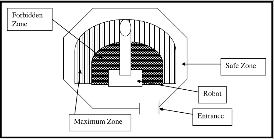
1.1 Robotic System 2
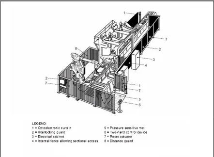
1.2 Safety Floor Marking of Robot Work Cell 3
2.1 The 6 Degree of Freedom (DOF) Robot 8
2.2 A Major Robot Components 9
2.3 A Cartesian Configuration 13
2.4 A Cylindrical Configuration 14
2.5 A Spherical Configuration 15
2.6 An Articulated / Jointed Arm Configuration 16
2.7 A Robot Work Envelope 28
2.8 Working Envelope for IRB1410 (Arc Pack) 29
2.9 Process the C++ Compiler 40
2.10 Structure of C++ Program 41
2.11 IPO Chart with a Flowchart in the Processing Column 43 2.12 Top View of Robot Workspace for 1 Robot 48 2.13 Top View of Robot Workspace for 2 Robots 49
3.1 Research Methodology 52
4.1 First Level User Interface 63
4.2 Second Level User Interface 64
4.3 Third Level User Interface 67
LIST OF TABLES
2.1 Type of ABB Robot 17
2.2 Type of FANUC Robot 19
2.3 Type of KAWASAKI Robot 21
2.4 Type of MOTOMAN Robot 23
2.5 Type of KUKA Robot 25
2.6 A Programmer Processes 33
2.7 An IPO Chart 42
LIST OF ABBREVIATIONS, SYMBOLS, SPECIALIZED
NOMENCLATURE
3D - 3 Dimensional
PSM1 - Projek Sarjana Muda 1 PSM2 - Projek Sarjana Muda 2
R.U.R - Rossum's Universal Robots DOF - Degree of Freedom
AC - Analog Current DC - Digital Current ABB - Asian Brown Boveri
ME - MOTOMAN Robotics Europe AB YEC - YASKAWA Electric Corporation OOP - Object-Oriented Programming
IDE - Integrated Development Environment OOED - Object-Oriented/Event-Driven
TOE - Task, Object, Event IPO - Input, Processing, Output CAD - Computer Aided Design
CHAPTER 1
GENERAL INTRODUCTION
1.1
IntroductionIn this world, there were about 750,000 robots working in industry worldwide [1]. The industrial robots were more advanced than before, they has increased in capability and performance through controller and the language development. Beside that, the mechanisms, sensing system and drive system also improved [1].
Figure 1.1: Robotic System
The industrial robot use in manufacturing industries makes a new challenge of safety system and robot installation. This valid is for all the people in the industries especially the worker who works in the robot working envelope. Injury rates for worker may be increased without proper safety system, robot installation software, safety workspace and safe working area. So, the need of safety system and robot installations software is important and necessary. All of these things are to ensure the hazard can be minimized and eliminated to an acceptable limit.
area. This software is expected to help the industry to set up the location of robot arm and improve the facility design and reduce hazards in the workspace.
[image:20.612.101.540.313.537.2]The 3D robot workspace and safe working area is used to avoid the accident during the operation of robot. By using this software, the safe working area of a robot can be determined. After that, draw a layout and build a fence to prevent the operator close to the robot. Beside that, it also have few arrangement for robot, the robot can arrange in a few arrangement depend the location in the factory. By using this software, we can save time, because it is faster than using calculator to get the exact distance of the safe working area. The figure 1.2 show the floor marking of the robot arm workspace
Figure 1.2: Safety Floor Marking of Robot Work Cell
Forbidden Zone : the area outside the work cell and has no restrictions on human movement.
Maximum Zone : is the area inside the work cell but out of reach of the robot arm. Safe Zone : is the area inside the robot work envelope and it cannot be
entered while the robot is in the automatic or run mode. Forbidden
Zone
Maximum Zone
Safe Zone
1.2
Objectives of the ProjectThe objectives of this project are as follows:
1. To evaluate current computer program to determine robot workspace and safe working area.
2. To design and develop 3D robot workspace and safe working area.
1.3
Scopes of the ProjectScopes of this project includes:
1. Identify and evaluate the suitable computer software to create a program to determine 3D robot workspace and safe working area.
2. Design and develop the computer software to determine 3D robot workspace and safe working area using the chosen software.
1.4
Layout of the ThesisThe general introduction about this project is provided in Chapter 1 that discusses about the problem statement carried out for this project named “Design and Develop a computer program of 3D Robot Workspace and Safe Working Area”, objectives and
scopes of this project briefly. Layout of this report is also presented in this chapter.
software. This chapter is also as a reference to implement this project. List of brand and type of industrial robot is presented in this chapter that will be used and applied in this project. Computer program and drawing software will be chosen and used to create, program and execute this project become success.
All of the method and analysis of the data used to implement this project is presented and described briefly in this chapter named Methodology chapter or Chapter 3. Flow chart of research methodology from start to end of this project is presented and explained briefly. Beside that, the sources of the data and information are described in research tool. And then project research planning for PSM1 and PSM2 that has been fixed in Gantt chart are outlined in this chapter.
The fourth chapter is on design and development of the computer program. The emphasis of this chapter is the output of this project and it also includes the analysis done during the implementation of this project and presentation of the user interface.
Chapter 5 provides a general discussion on the results of this project, stressing the significance and several implications of the findings of the project undertaken. Overall of this project will be described and concluded in the last chapter (chapter 5). Beside that, any suggestion to improve and develop this project in the future will be outlined in this chapter. All the result and finding drawn from this research will be concluded in this chapter.
1.5
Concluding RemarkCHAPTER 2
LITERATURE REVIEW
2.1 Introduction
2.2 Robot and its components
2.2.1 Robot
A robot can be defined as a reprogrammable, multifunctional manipulator which designed to move materials, parts, tools or special devices through variable programmed motions for performing a variety of tasks [6].