SUPERVISOR DECLARATION
“I hereby declare that I have read this thesis and in my opinion this thesis is sufficient in terms of scope and quality for the award of the degree of
Bachelor of Mechanical Engineering (Automotive).”
Signature: ...
AIR AND FUEL FLOW ANALYSIS OF A SINGLE CYLINDER ENGINE
NUR AMEELIA BINTI ROSLI
This report is submitted in partial
fulfillment of the requirements for the award of a
Bachelor in Mechanical Engineering (Automotive) with honours
Faculty of Mechanical Engineering Universiti Teknikal Malaysia Melaka
ii
DECLARATION
“I hereby declare that the work in this thesis is my own except for the summaries and quotations which have been duly acknowledge.”
Signature :………..
Author : NUR AMEELIA BINTI ROSLI
iii
iv
ACKNOWLEDGEMENT
I would like to express my heartfelt gratitude to my supervisor Dr. Musthafah bin Mohd. Tahir for his encouragement, patience and support to complete my project and thesis writing.
I would also like to thank my senior Mr. Abdul Muhaimin bin Mohd. Shafie who helped me a lot with the understanding of the simulation and share all the knowledge related to my research field. Also my team mates who helped me all the way from the start till the completion of this project.
v
ABSTRAK
vi
ABSTRACT
vii
TABLE OF CONTENT
CHAPTER CONTENT PAGES
DECLARATION ii
DEDICATION iii
ACKNOWLEDGEMENT iv
ABSTRAK vi
ABSTRACT iv
TABLE OF CONTENT vii
LIST OF TABLES ix
LIST OF FIGURES x
LIST OF SYMBOL xii
LIST OF APPENDIX xiv
LIST OF ABBREVIATION xiii
CHAPTER I INTRODUCTION 1
1.1 Overview 1
1.2 Problem Statement 2
1.2 Objectives 3
1.3 Scopes Of Study 3
CHAPTER II LITERATURE REVIEW 4
2.0 Overview 4
2.1 Internal Combustion Engine 4
2.2 Compressed Natural Gas 7
viii
CHAPTER CONTENT PAGES
2.4 Flow Motion In Combustion Chamber 13
2.4.1 Swirl Theories 17
CHAPTER III METHODOLOGY 18
3.1 Overview 18
3.2 Project Flow 19
3.3 Creation of 3D Engine Geometry 20
3.4 CFD Simulation Analysis 23
3.5 Geometry Modification 24
3.5.1 Meshing 26
3.5.2 Solver Setting 30
CHAPTER IV RESULTS AND DISCUSSIONS 31
CHAPTER V CONCLUSION 47
REFERENCE 48
APPENDIX 50
Appendix A 50
Appendix B 53
Appendix C 57
ix
LIST OF TABLES
NUM. CONTENT PAGE
2.1 Composition of Natural Gas in Comparison with Gasoline 8 3.1 Mass and Mole Fraction of Methane, Oxygen and Nitrogen 29
4.1 Velocity Contour on X-Y Axis Indicating Swirl 40
4.2 Velocity Vector on X-Z Axis Indicating Tumble 42
x
LIST OF FIGURES
NUM. CONTENT PAGE
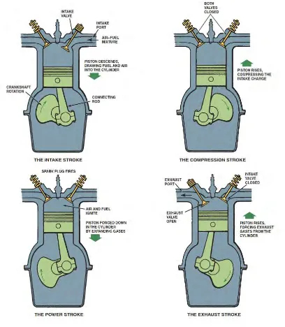
2.1 Four Stroke Engine Operating Cycle 6
2.2 Meshed Geometry of a Cylinder 11
2.3 Contour of Static Pressure 12
2.4 Contour of Static Temperature 12
2.5 Turbulence Intensity as a Function of Engine Speed 14
2.6 Swirl Motion in Engine Cylinder 15
2.7 Air Entering the Cylinder from Tangential Direction 15
2.8 Tumble Occurs Around Circumferential Axis 16
3.1 Flow Chart of Project For Psm 19
3.2 Robin EY20D Single Cylinder Engine 21
3.3 Drawing of Parts involves in Analysis 22
3.4 Assembly Drawing of a Simplified Single Cylinder Engine 23
3.5 Elements in CFD Simulation 23
3.6 Simplified Engine Model in Ansys Geometry 24
3.7 Cavity in the engine converted into solid part 25
3.8 Fuel Inlet Added to the Intake Port 26
3.9 Boundary Condition 27
3.10 The Tetrahedral Meshing of Simulation Geometry 30
4.1 Plane A,B.C And D on X-Y Axis 32
4.2 Plane 1,2 And 3 on X-Z Axis 32
4.3 Cutaway Geometry Indicating Plane on Y-Z Axis 33
xi
4.5 Flow of The Mixture in the Cylinder Taken at Plane A
(At 1.302 mm Valve Lift) 35
4.6 Flow of the Mixture in the Cylinder Taken at Plane A
(At 2.604 mm Valve Lift) 36
4.7 Flow of the Mixture in the Cylinder Taken at Plane A
(At 3.906 mm Valve Lift) 37
4.8 Flow of the Mixture in the Cylinder Taken at Plane A
(At 5.208 mm Valve Lift) 38
4.9 Flow of the Mixture in the Cylinder Taken at Plane A
(At 6.51 mm Valve Lift) 39
xii
LIST OF SYMBOL
kJ/kg kilo Joule per kilogram MJ/kg Mega Joule per kilogram Pa Pascal
m/s meter per second Flow rate
A Area
u Fluid velocity
S Stroke length
N engine speed per one revolution Ūp average piston speed
rpm revolution per minute kg/mol kilogram per mol
ω angular speed
ut swirl tangential speed Ūp average piston speed °C degree celcius NOx Nitrogen Oxide
C-H ratio Carbon-hydrogen ration
CO Carbon Oxide
xiii
LIST OF ABBREVIATION
CFD Computational Fluid Dynamic
CNG Compressed Natural Gas
LNG Liquid Natural Gas
SI Spark Ignition
ICE Internal Combustion Engine
NG Natural Gas
NGV Natural Gas Vehicle
TKE Turbulence Kinetic Energy
PSM Projek Sarjana Muda
FYP Final Year Project
bTDC before Top Dead Centre
BDC Bottom Dead Centre
TDC Top Dead Centre
2D 2-Dimension
3D 3-Dimension
SR Swirl Ratio
CAD Computer Aided Drawing
vol volume
AF Ratio Air Fuel Ratio
xiv
LIST OF APPENDIX
NUM CONTENT PAGES
A Calculation 51
B Simulation Result 54
C Drawing 58
1
CHAPTER I
INTRODUCTION
1.1 OVERVIEW
2
1.2 PROBLEM STATEMENT
Research on using Compressed Natural Gas (CNG) as a transport engine fuel has found many advantages over petrol. The advantages of CNG compared to petrol are unique combustion and suitable mixture formation due to high octane number of CNG, engine operates smoothly with high compression ratios without knocking, CNG with lean burning quality will leads to lowering exhaust emissions and fuel operating cost, CNG has a lower flame speed, engine durability is very high, the flame speed of Natural gas is lower compared to petrol (Aslam et al., 2006). Besides that, CNG is attractive for five reasons. It is the only fuel cheaper than gasoline or diesel. It has inherently lower air pollution emissions. It has lower greenhouse gas emissions. Its use extends petroleum supplies, and there are large quantities of the fuel available in the world.(Abu Bakar, 2008).
3
1.2 OBJECTIVES
There are four objectives to be fulfilled by the end of this project. The objectives are as follows;
1. To simulate flows in the engine using ANSYS Fluent for a single cylinder engine at intake stroke
2. To investigate the effect of different valve lift to the flow in the engine 3. To produce geometry drawing and analysis at intake stroke
1.3 SCOPES OF STUDY
In completion of this project, the EY20D single cylinder spark ignition engine was modeled in CATIA for further analysis. The engine dimensions was taken to produce 3D geometry drawing before using ANSYS Fluent software to analyze the air and fuel flow at intake stroke.
4
CHAPTER II
LITERATURE REVIEW
2.0 OVERVIEW
This chapter will cover the review on internal combustion engine, computational fluid dynamic and fluid motion within combustion chamber.
2.1 INTERNAL COMBUSTION ENGINE
Internal combustion engine (ICE) is a heat engine that converts chemical energy in a fuel into mechanical energy, usually made available on a rotating output shaft (Pulkrabek, 2008). The output of the engine which is the rotating crankshaft received energy from the mechanical linkage, where expansion process takes place due to high-pressure gas expand against the mechanical mechanisms of the engine.
5
the final use. Applications of this process include the propulsion of a vehicle or stationery engines to drive generators.
In the early development of internal combustion engine back in 1800s, the development of the automobile was also growing. During that time, the lack of good and consistent fuel was a major drawback in engine development (Pulkrabek, 2008). New discoveries of crude oil in Pennsylvania trigger the development of reliable fuels that could be useful for the founding of these new engines. The technologies that stimulate the internal combustion engine development are not only the development of reliable fuels but also the pneumatic rubber tire.
There is numerous classification of internal combustion engine which fall into types of ignition, basic design, numbers of cylinders, engine cycle and fuel used. Most of internal combustion engine are reciprocating engines where the pistons went back and forth in the cylinder. At closed end at each cylinder locates the combustion chamber. There can be a single cylinder or more than one cylinder which can reach more than 20 cylinders where the piston is connected to the crank shaft.
6
7
Internal combustion engine can be classified based on the fuel used. Examples of fuel used are;
i. Gasoline
ii. Diesel Oil Or Fuel Oil iii. Natural Gas
iv. Liquid Petroleum Gas v. Alcohol (Ethyl, Methyl) vi. Dual Fuel
vii. Gasohol
Natural gas is a mixture of components, consisting mainly of methane (60-98%) with small amount of other hydrocarbon fuel components. It contains various amounts of N2, CO2, He and traces of other gases (Pulkrabek, 2008). A compressible natural gas can be stored for a later used for example in vehicle. This gas is called compressed natural gas or CNG. CNG requires a much larger volume to store the same mass of natural gas and the use of very high pressure on about 200 bar or 2900 psi (Stone, 1997). Natural gas also can be stored as liquid natural gas or LNG at pressures of 70 to 210 kilo Pascal and a temperature of approximately -160°.
2.2 COMPRESSED NATURAL GAS
Natural gas is naturally occurring form of fossil energy and therefore renewable. Natural gas occurs as gas under pressure in rocks beneath the earth’s surface or often in solution with crude oil as a volatile fraction of petroleum. It is naturally hydrocarbon energy formed in the earth’s crust by millions of years of biological action on organic matter (Ramadhas, 2011). Thus, it does not require undergoing refining process as petroleum.
8
carbon dioxide. CNG has higher motor octane number making it suitable for spark ignition engine or a designed gas engine with higher compression ratio.
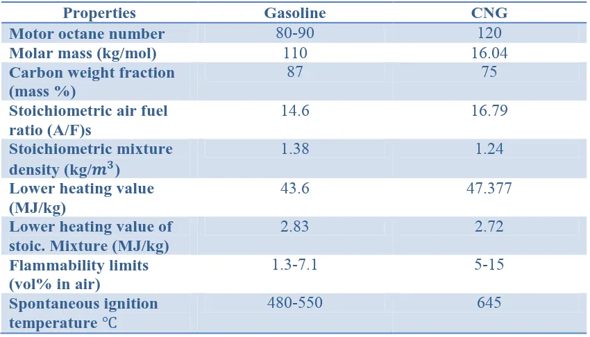
[image:23.595.107.532.286.529.2]As been said by Bhandari, K. et al (2005), the higher octane number in Compressed Natural Gas (CNG) enable the engine to operate at higher compression ratio (CR) and it may higher efficiency and higher power generated. CNG shows higher ignition temperature compared to gasoline. Besides, it is lighter than air density. Due to those properties, CNG is likely to be safer than gasoline. Composition of natural gas in comparison with gasoline is shown in Table 2.1.
Table 2.1: Composition of natural gas in comparison with gasoline
Properties Gasoline CNG
Motor octane number 80-90 120
Molar mass (kg/mol) 110 16.04
Carbon weight fraction (mass %)
87 75
Stoichiometric air fuel ratio (A/F)s
14.6 16.79
Stoichiometric mixture
density (kg/ )
1.38 1.24
Lower heating value (MJ/kg)
43.6 47.377
Lower heating value of stoic. Mixture (MJ/kg)
2.83 2.72
Flammability limits (vol% in air)
1.3-7.1 5-15
Spontaneous ignition temperature
480-550 645
Natural gas is compressed and stored to be used in automobiles. It is necessary to store it in compact form to reduce the weight of the vehicle. The storage capacity of CNG is in a range from 20 up to 100 liters. The cylinder storage must able to handle pressures of 600 bar. This is a safety measure if ever the storage cylinder is exposed to fire.
9
Ramadhas, A. S (2011) has concluded that CNG contains the following advantages; 1. Environmental: CNG vehicles produce far less of all regulated pollutants
compared to gasoline or diesel vehicles including Nox and particulate matter. Natural gas has low C-H ratio hence lower CO and HC emissions. CNG vehicles produce far less unregulated air toxics and greenhouse gases. Due to proper combustion of gas-air mixtures, reduced unburned HC emissions will reduce the environmental pollution of visible photochemical smoke.
2. Energy security: Natural gas usage reduces the consumption of gasoline and diesel fuel.
3. Operating cost: Cheaper than gasoline and diesel fuel.
4. Distribution efficiency safety: Natural gas has a higher ignition temperature than gasoline or diesel. Its density that is lighter than air makes it disperses quickly if leakage of fuel is to happen. This shows the safest and most efficient energy distribution system. The explosive limit of natural gas-air mixtures is higher than diesel-air mixtures. Natural gas requires approximately 5% of volume compared to 2% for propane and 1% for gasoline vapor for continuous flame propagation. This means natural gas is safer than other fuels.
5. Flexibility: CNG vehicles can be produces distinctively and bi-fuel versions. CNG vehicles are suitable at the area where natural gas is available. While bi-fuel vehicles can operate both natural gas and gasoline bi-fuel as they have storage tanks on board. This kind of vehicle can operate by using natural and easily switch to gasoline if the area does not provide natural gas supply. It is economical and environmentally friendly.