PROJECT COMPLETION REPORT FOR
SHORT TERM RESEARCH GRANT
Principle Researcher: Faizil Bin Wasbari Co-Researcher: 1. Ahmad Anas bin Yusof
2. Suhaimi bin Misha 3. Mohd Basri bin Ali 4. Mohd Nizam bin Sudin Project Code No.: PJP/2008/FKM(11)S418 Report Submission Date: 6 September 2012
Department of Thermal-Fluids
FACULTY OF MECHANICAL ENGINEERING UNIVERSITY TEKNIKAL MALAYSIA MELAKA
ENHANCING ECO-FRIENDLY HYDRAULIC TECHNOLOGY: THE DEVELOPMENT OF LOW PRESSURE WATER HYDRAULIC
MANIPULATOR FOR SMALL AND MEDIUM INDUSTRIES IN MALAYSIA
Special dedication to my family, my fellow co-researcher and those who helped me to finish this project.
ACKNOWLEDGEMENT
Alhamdulillah, I am most grateful and thankful to ALLAH the Almighty for His blessing, authorization and kindness that has allowed me to conduct and complete this project.
My most appreciation and grateful is to Universiti Teknikal Malaysia Melaka (UTeM) for giving me chances and funding for this research. I am also indebted to Center For Research and Innovation Management (CRIM) who has managed the procedure of conducting research from application, budgeting until the closing of this research. Unforgotten to Fakulti Kejuruteraan Mekanikal (FKM) who has providing a research platform in term of lab facilities and tools towards the successfulness of this research.
I would also like to thank all those who had contributed directly and indirectly, to make this project successful especially to Mr. Ikhmal Hisham Bin Ibrahim@Ibarahim, the technicians of Hydraulics and Pneumatic Laboratory for his help and opinion during the implementation of this project.
ABSTRACT
This thesis presents a study on development of low pressure water hydraulic system. This study mainly focuses on building a hydraulic power unit, design of control system; fabricate water hydraulic power unit and system and run testing procedures on the testing system. The purpose of this study is to test the performance of water hydraulic when low pressure is applied. Besides that other purpose of this
study is to use Programmable Logic Controller (OMRON) as the control system for
this low pressure water hydraulic system. Water hydraulic system is commonly used in industries years ago, but then water hydraulic is replaced with oil as pressure medium because of disadvantages of using water as pressure medium. This study is done to explore the limitations of using water hydraulic system and the solution to solve the occurred problems. A testing system was designed and simulated by using
Programmable Logic Controller (OMRON) which is widely used in industries
nowadays. From the simulation, the motion of cylinder is shown. This simulation can help reduces time in designing and assembling the testing system correctly. Several tests were done with the aid of the testing system for low pressure water hydraulic system. The same tests were also done on pneumatic system and hydraulic system for comparison in terms of performance. The performance of system was tested in terms of breakaway pressure, internal leakages, speed of stroke and output force. The results were recorded and analysed to verify the ability of low pressure water hydraulic system and to make comparison between pneumatic system and hydraulic system. As a result, low pressure water hydraulic system is applicable. However, improvements are needed to make sure the system is more suitable and efficient.
TABLE OF CONTENTS
ACKNOWLEDGEMENT ... 3
ABSTRACT ... 4
INTRODUCTION ... 6
LITERATURE REVIEW ... 9
METHODOLOGY ... 27
DESIGN ... 35
DEVELOPMENT OF WATER HYDRAULIC SYSTEM ... 50
RESULT ... 57
ANALYSIS ... 65
DISCUSSION ... 78
CONCLUSION AND RECOMMENDATION ... 83
REFERENCES ... 86
CHAPTER I
INTRODUCTION
1.1 OVERVIEW
Water hydraulic system is a fluid power system. Fluid power is the energy generated by using a pressurized medium to accomplish work. A development is carried to study low pressure water hydraulic system. Most hydraulic system use oils as power transmitting medium to work in high pressure, while pneumatic system use air to power actuator in low pressure. Water-based fluids are often been used in hydraulic system due to its non-toxic, non-flammable characteristic to fulfill the hygiene requirement.
This development is about using water as a medium in a low pressure fluid power system. Usually, hydraulic system is design for high pressure application. In this case, pneumatic system which is design for low pressure that works for below 10 bars will be used for testing.
1.2 OBJECTIVE
This project is about developing a low pressure water hydraulic system. The objectives are as follow:-
i) To design and fabricate low pressure water hydraulic test rig.
ii) To find test rig performance in term of manipulator velocity and power.
iii) To make comparison with the existing system.
1.3 SCOPE
The scope of the project is generally are as below:-
i) Build a water hydraulic power unit.
ii) Assemble a water hydraulic robotic system.
iii) Testing the uses of water in low pressure fluid power system.
1.4 PROBLEM STATEMENT
Both hydraulic and pneumatic systems are widely used in industries. The common materials used to transfer power in the mentioned systems are oil and air. New materials as pressure medium are developed and water is found as a suitable medium according to its characteristic of non-toxic, nonflammable and no adverse effect on the environment. Several researches and testing were done and proof that water able to be used in hydraulic system as oil can. However, for pneumatic system with low pressure, further development and testing are needed to verify the problem may occurs when water is using.
1.5 PROJECT OUTLINE
This report on “Development of Low Pressure Water Hydraulic System” is divided into 10 chapters.
Chapter 1 introduces the audience to the general background of this research, the problem statement, project objectives, as well as the project scope. Also, it offers an overall view of the project outline.
Chapter 2 is a compilation of required information and literature reviews gathered from electronic media, published journals, and books.
Chapter 3 explains about the methodology used in the study of low pressure water hydraulic system. The methodology consists of 3 main stages; building up the power unit, design the testing system and develop the testing system.
Chapter 4 will present the results of simulation of the designed testing system. This chapter will also discuss related assumptions in validating the simulations.
The development process of low pressure water hydraulic testing system will be explained in Chapter 5.
Chapter 6 will show the results of tests that have been performed.
Chapter 7 will present the results of simulation of the designed testing system.
Chapter 8 will discuss about the findings and analysis of result.
Finally, chapter 9 will present the conclusion and the recommendation for further study in low pressure hydraulic system.
CHAPTER II
LITERATURE REVIEW
This chapter presents a brief review of low pressure water hydraulic system literature which consists of several numerous studies from the past and presents. Beside that, basic theories of fluid power system will be presented in this chapter. These studies are features the theories that are explained application and phenomena of hydraulic system and low pressure fluid power system.
2.1 LITERATURE REVIEW
This section presents the studies on the related literature of Low Pressure Hydraulic System that has been published on a research area. Various journal, books and technical paper have been studied to understand the topic area of this project.
2.1.1 DEFINITION OF LOW PRESSURE
This project carries out a study about a low pressure water hydraulic system. The pressure range in fluid power application may vary a lot. To perform a task that requires small force, the pressure needed may be less than 1 bar. However, for heavy duty industries, the pressure in a fluid power system may up to hundred bars.
According to Alavudeen and Shanmugam (2007), the pressure range in fluid power application is divided into four categories, which are:-
Low pressure range : up to 10 bar
Medium pressure range : up to 15 bar
High pressure range : up to 40 bar
Ultra High pressure range : up to 400 bar
2.1.2 INTRODUCTION OF WATER HYDRAULIC SYSTEM
The two common power transmitting systems are hydraulic and pneumatic system. Ordinary, oil is used as pressure medium in hydraulic system which operating with high pressure. However, as technology improved, new materials and new design methods were developed, water become a possible pressure medium to be used in hydraulic system. The advantages of water as pressure medium compare to oil are:
Negligible cost
The cost of water is relative low compare to mineral oil. Therefore, it is cost effective to use water instead of oil in hydraulic machinery in the long term.
Non-toxic
The vapor of mineral oil is harmful to human body. The health of workers are at risk to breath in oil vapor or suffer exposure of skin and eyes to the vapor.
Nonflammable
Water is fireproof that cannot burn in any condition.
No adverse effects on environment
Water is environmentally friendly and does not give any environment hazard.
Fulfill the hygiene requirement
There is negligible product contamination in event of leakage of water hydraulic system. The water will simply evaporate without leaving residue when leaks or spills of a water hydraulic system occurred. It has been stated that “As much as 85% of all hydraulic fluid eventually leave their system through slow leaks, catastrophic line breaks or failures of fittings and seals” (Joseph, 1996)
However, there are disadvantages in water hydraulic system. The following shows the inherent disadvantage of water:-
Corrosion
According to Krutz and Chua (2004), due to the dissolved gases in the water, the piping and components of the water hydraulic system may face the problem of corrosion. Corrosion resistance materials that are move expensive and even corrosion inhibiting chemicals are needed.
Lubrication
Water lacks of the characteristic of lubrication of oil. This poor lubricant characteristic of water makes the water hydraulic system unable to offer faster automation for industrialization.
Freezing
Freezing problem occurs on the water hydraulic system that installed outside or in unheated buildings. Krutz and Chua (2004) stated that the volume of water expands by 9% as it freezes. Severe damage may happen in a water hydraulic system. This characteristic of water limits application of water hydraulic system in low temperatures unless water is heated or antifreeze solutions are added.
Space Requirement
According to Petraitis (n.d.), the size of water hydraulic components are larger than oil hydraulic components. “The larger component size along with the piping configuration requires a good deal more real estate for installation”
(Petraitis, n.d.). Although some compact model directional control sub-baseplate mounted valves are available in market now, these are limited to a few sizes.
2.1.3 WATER QUALITY
Basically, standards of water quality were determined in the research done by Hilbrecht and Danfoss. The components prescribe in this project are type of stainless steel. In order to prevent corrosion, content of chloride (Cl) must lower than 200 mg/l and water’s pH value should be between 6.5 to 8, which in neutral range. (Hilbrecht and Danfoss, 2000)
According to Hilbrecht and Danfoss, raw water is not a suitable type of water to be used in hydraulic system, unless a filter with large filterability is attached to the hydraulic system. The quality of raw water may differ for water from different places. Under a long term visual observation, raw water in Melaka has a poor quality as unknown contaminations often come with raw water.
Based on the research, water quality used in hydraulic system is recommended to be at least drinking water quality with filtration at least 10μm absolute. From the consideration of contamination content, technical water that been demineralized will be the best choice as pressure medium. However, the demineralized water has 2-3 times higher dynamic friction coefficient compare with drinking water. Due to this characteristic, customized component might be needed.
“The acceptable amount of bacteria in water depends on the application of the water hydraulic system in question.” (Hilbrecht and Danfoss, 2000)
Drinking quality will be good enough for industries application, whereas high water quality is needed for phama-industries. The germination index (number of bacteria per ml) must be control as low as possible. In order to decrease the germination index, nutritional value should be controlled. Without nutrients, bacteria are unable to live/reproduce.
In a development of modern water hydraulic system (Steel, n.d.), it is stated that soluble oil should be added into the water to help with lubrication problem that occurs in water hydraulic system.
2.1.4 CHARACTERISTICS OF HYDROSTATIC BEARING/SEAL PARTS
FOR WATER HYDRAULIC PUMPS AND MOTORS
According to Wang and Yamaguchi (2002), the two common power transmitting systems are hydraulic and pneumatic system. Ordinary, oil is used as pressure medium in hydraulic system which operating with high pressure. However, as technology improved, new materials and new design methods were developed, water become a possible pressure medium to be used in hydraulic system.
Wang and Yamaguchi (2002) presented their study of the characteristic of disk-type hydrostatic thrust bearings supporting concentric loads, simulating the major bearing/seal parts of water hydraulic pumps and motor in this journal. They evaluated characteristics from the relationships among the load-carrying capacity, pocket pressure, film thickness, and leakage flow rate.
In this experiment, a hydrostatic thrust bearing, cylindrical nozzle, oil hydraulic cylinder giving concentric loads on the test bearing, and electric motor performing rotation operation were used. They compose the thrust bearing of the upper specimen with the pocket and the lower disk specimen connected to the motor. Stainless steel and thermoplastic were used as the material of specimen in this experiment. These materials are used to avoid the occurring of rust as water is used as power medium.
The method of testing is mentioned in this paper too. First, oil cylinder generated load and act on upper specimen. The upper specimen is pressed and contact with lower specimen. Pressurized water is supplied to the hydrostatic pocket through cylindrical nozzle. The water used in this experiment is tap water that
filtered through filter with 3 μm absolute. According to Hilbrecht and Danfoss (2000) Water as Pressure Medium in Water Hydraulic System, the quality of water filled into a water hydraulic system always has minimum of drinking water quality and filtration to be better or equal to 10 μm absolute. 3 μm absolute filtration for water used is fulfilled the requirement of water quality.
The leakage flow rate across the bearing clearance is set to almost equal to zero, by adjusting the load. The temperature of leakage is under controlled, within 23-27 ºC. Sensors are turn on to measure the data of system. Gap sensors (accuracy within 1μm) with reference zero point is set on, is used to measure the film thickness. Load cell sensor is used to measure the load. A measuring cylinder is used to measure the leakage flow rate and a pressure sensor is used to measure pressure of the system. All the sensors were calibrated before this experiment to give the most accurate results.
In this case, the pressure was set to 9.0, 5.0, and 2.0 MPa. The result is given under these 3 pressures. Graphs are plotted based on the obtained result. In the graph of pocket pressure vs. balance ratio, we found that when pocket pressure increases, balanced ration increases too, for all 3 supplied pressures (9.0, 5.0 and 2.0 MPa). Besides, under each supplied pressure, a graph of pocket pressure vs. balanced ratio is constructed based on the materials.
After the experiment done, Wang and Yamaguchi (2002) conclude that material more compressible than stainless steel can improve the load carrying capacity of the hydrostatic bearing/seal parts. It is effective to design compact and light water hydraulic pumps and motors.
2.1.5 RESEARCH ON LOADING OF THE SOFT AND HARD TISSUES BASED ON WATER HYDRAULIC SYSTEM WITH FIBER BRAGG GRATING SENSING
A study on loading of the soft and hard tissues based on water hydraulic system with fiber bragg grating sensing was done by Huang et al (2006). The
designate experiment test bed, controller implementation and experiments of the water hydraulic system for soft and hard tissues via Fiber Bragg Grating (FBG) sensing measurement is carried out in this paper. FBG is used instead of conventional strain gage in this research. The system that developed in this research can be used to acquisition the loading response in between the soft and hard tissues and observe the loading condition.
Hydraulic system is widely used in industries sector. However, the output force of hydraulic system is hard to control due to the dynamics characteristics of hydraulic, mechanical stiffness of the machine and the bulk modulus of water with dissolved air. Due to the environment point of view, water hydraulics has been applied to the biomedical research.
According to the paper (Huang et al, 2006), a fiber grating is an optical fiber
device for which the refractive index in the core is perturbed to form a periodic or quasi-periodic index modulation profile. It can be roughly classified into two main categories, which is Fiber Bragg Gratings (FBGs) and Long Period Fiber Gratings (LPGs). FBG is used in this research due to electromagnetic interference immunity, light weight and small size, flexibility, high temperature and radiation tolerance, and it can be multiplexed in a series of arrays along a single fiber.
In this system, the pressured force on the tissue is controlled by the servo motor positioning and calibrated through the pressure sensor feedback signal. Therefore, a precise positioning of the cylinder movement for actuating the tissues is driven by lead screw servo motor. Signal transferring mechanism based on the dynamic response of interested tissue interface can be obtained via the developing FBG sensing apparatus.
The system contains an outer closed loop hydraulic force control, and inner loop for cylinder movement. The Water Hydraulic system used the closed-loop devices for acquiring the signal transferring mechanism of the soft and hard tissues. Silicone rubbers and tempron materials were used to represent the soft and hard tissues in the present system. In my project, the system used is relative simple. A Pick & Place robot which consists of several low pressure cylinders is used to acquiring solid objects.
In the research done (Huang et al, 2006), tap water was used as the working
fluid. The open end of the cylinder was directly connected with PVC tube segment. The displacement and velocity of the cylinder's piston were controlled by the PC Bus motion controller interfacing board. However, according to technical paper written by Hilbrecht and Danfoss (2000), the quality of tap water may be deteriorated. Therefore, drinking water will be used as the working fluid in my study.
In the research (Huang et al, 2006), pressure sensor is used to measure the
magnitude. This pressure sensor used is pressure transducer AST3100 with 5 volts output for the full scale of 533 psi loading condition. It was connected to compatible personal computer (PC) and used to integrate the acquired data from both the pressure sensor and the servo position counter and to output commend for controlling motor's positioning.
The relation between displacement and pressure was studied in this research
(Huang et al, 2006). Acquisitioned pressure force with respect to cylinder
displacement is plotted. With the aid of computer, the equation of piston displacement with respect to the pressure force is found out.
Dynamic Signal Analyzers (Model 20-42, SigLab, DSP Technology Inc.) in frequency domain is used for system identification in this research (Huang et al,
2006). The zeros and poles of the water hydraulic system are produced and experimental result of the system Bode plot is plotted. Besides, MATLAB's nonlinear control design (NCD) toolbox is used for the feedback control design of the water hydraulic system in this research.
Sensor of Fiber Bragg Grating is used to measure deformations and strain in this study (Huang et al, 2006), instead of strain gage. This is because stain gages
require electric circuit device with inevitable electronic noises and not suitable for substance with liquid environment. In this paper, the characteristic about FBG is utilized as strain sensor. Essentially, a FBG was bonding to an object and giving the return of varying stress result.
The result of this research (Huang et al, 2006) is found by using FBG
Linearity Test. Experimental result tells axial strain is almost linear to wavelength shift quantity and committed to the fiber grating's principle. Consequently experimental apparatus with FBG exhibits a high sensitive, accurate and stable strain sensor here.
In this research (Huang et al, 2006), single-rod cylinder creates actuating
movement through PVC tube via the water hydraulic force transmitted to the target of soft and hard tissues. Relation between the position of the cylinder's piston and wavelength shift quantity is depicted after the study done. Delayed system phenomena of the soft and hard tissues are obvious. In general, any dissolved air is an integral part of the fluid. Because air needs a long time to react with pressures, the total volume of the fluid in tube is dynamically changing during experiment.
2.2 THEORY AND BACKGROUND
Hydraulic system is widely used in industries area nowadays. In this section, a brief explanation of the theory and background of fluid power system is carried out. The studies about the components and formulas needed for hydraulic system is done in this section.
2.2.1 INTRODUCTION OF FLUID POWER SYSTEM
There are three types of power transmission, which are mechanical power transmission, electrical power transmission and fluid power transmission. Fluid power is the technology of generates, controls, and transmits pressurized fluids to accomplish work. It encompasses the utilization of fluid as media for the transmission of energy. In fluid power, the energy comes from the flow and the pressure, but not from the kinetic energy of the flow. Fluid power is subdivided into hydraulics and pneumatics, as the term of fluid refers either to gases or to liquids.
The word hydraulics is based on the Greek word for water. It is the study of the physical behavior of fluid at rest and in motion. The word pneumatics is a derivative of the Greek word pneuma, which means air, wind, or breath. It involve of the use of gaseous pressure and flow in transmitting energy. The main difference between hydraulic and pneumatic would be the medium used in system. Pneumatics uses an easily compressible gas such as air or a suitable pure gas, while hydraulics uses relatively incompressible liquid media such as oil or water.
A fluid power system accomplishes 2 main purposes. First, it provides substantial force to move actuators in locations some distance from the power source, where the two are connected by pipes, tubes, or hoses. This is a decided advantage over systems using gears, shaft, and chains, particularly as the location of output actuators becomes less accessible. Second, fluid power systems accomplish highly accurate and precise movement of the actuator with relative ease. This is particular important in such applications as the machine tool Industry where tolerances are often specified to one ten thousandth of an inch and must be repeated during several million cycles.
2.2.2 BASIC COMPONENTS IN FLUID POWER SYSTEM
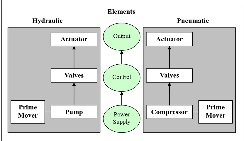
A fluid power system may consist of various components. No matter how complex a fluid power system is, the components can be group into three elements,
which are power supply, control and output. Figure 2.1 shows the elements of fluid power system.
Figure 2. 1: Element of fluid power system
2.2.2.1Power Supply
The power supply unit for hydraulic system and pneumatic system are different. For hydraulic system, hydraulic reservoir and pump are needed, while for pneumatic system, pneumatic reservoirs and air compressor is needed.
The hydraulic reservoir holds excess hydraulic fluid to accommodate volume changes when cylinder extension and contraction, temperature driven expansion and contraction, and leaks. The reservoir is also designed to aid in separation of air from the fluid and also work as a heat accumulator to cover losses in the system when peak power is used.
Pump is used supply fluid into the hydraulic system. Pressure in the system develops in reaction to the load. Pumps have a power density about ten times greater than an electric motor. They are driven by prime mover such as internal combustion engine, connected through gears, belts, or a flexible electrometric coupling to reduce vibration.
Power Supply Output
Control Elements
Pneumatic Hydraulic
Actuator
Valves
Prime
Mover Pump
Actuator
Valves
Prime Mover Compressor
There is various type of pump, which are gear pump, vane pump, axial piston pump, radial piston pump. Piston pumps are more expensive than gear or vane pumps, but provide longer life operating at higher pressure, with difficult fluids and longer continuous duty cycles. Piston pumps make up one half of a hydrostatic transmission.
2.2.2.2Control
There are three type of control valve needed in a hydraulic system, which are directional control valves, pressure valve and flow control valve.
Directional control valves route the fluid to the desired actuator. They usually consist of a spool inside a cast iron or steel housing. The spool slides to different positions in the housing, intersecting grooves and channels route the fluid based on the spool's position.
Pressure valves are divided into pressure relief valves, pressure reducing valves and sequence valves. Pressure relief valve are used to prevent overloading and hydraulic line/seal rupture. Pressure reducing valves reduce the supply pressure as needed for various circuits. Sequence valves control the sequence of hydraulic circuits by using pressure.
Flow control valves interact with pressure valves to affect the flow rate. They are used to control or regulate the speed of motion of the power components.
2.2.2.3Output
The energy output of a fluid power system refers to actuator. Actuators are
devices to convert fluid power into mechanical power. There are two forms of actuator, which are cylinder and motor. Cylinders are linear actuators that generate linear movements through the pressure on the surface of the movable piston, while motors are rotary actuators that generate rotary or swivel movements instead of linear movements.
2.2.3 FORMULA/CALCULATION
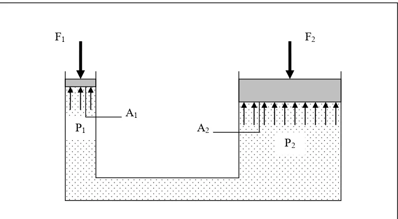
Pascal's law is the basis of hydraulic drive systems. Pascal’s law states that the pressure exerted on a confined fluid is transmitted undiminished in all direction, and acts with equal force on equal areas, and at right angles throughout the vessel or systems. (Hehn, A.H., 1993)
Pressure (P) is defined as force (F) per unit area (A). In SI standard, the unit
of force is in Newton (N), area is in square meters (m2). Therefore, the SI unit of
pressure is in N/ m2, which is also known as Pascals (Pa)
F P
A
= (2.1)
As the pressure in the system is the same, the force that the fluid gives to the surroundings is therefore equal to pressure x area. In such a way, a small piston feels a small force and a large piston feels a large force.
Figure 2. 2: Multiplication of force
Figure 2.2 shows the multiplication of force in a fluid power system. By using the formula 2.1, the pressure of both sides of system can be calculated as shown below.
1 1
1
F P
A
= and 2
2 2
F P
A
= (2.2)
From the definition of Pascal’s Law, the pressure of fluid in the system is equal.
1 2
P =P (2.3)
Thus, a new equation can be formed as shown in equation 2.4.
1 2
1 2
F F
A = A (2.4)
F1 F2
P1
P2 A1
A2
The basic formulas that use in hydraulic system are as shown below.
Fluid Pressure. P
F P
A
=
Fluid Flow, Q
Q= ×A v (2.5)
Fluid Work. W
W = ×P V (2.6)
Input Power (pump)
2 i
Power= π ×N T (2.7)
Hydraulic Power
Power= ×P Q (2.8)
Output Power (motor)
2 o
Power= π ×N T (2.9)
Output Force (cylinder)
F = ×P A (2.10)
Output Power (cylinder)
Power= ×F v (2.11)
2.2.4 FLUID POWER APPLICATIONS
Fluid power system have almost unlimited application in the production in nearly all sectors. Among them are agriculture, aerospace and aviation, construction, defense, manufacturing and machine tool, marine, material handling, mining, transportation, undersea technology, and public utilities. Hydraulics and pneumatics are similar in many ways, but there are clear reasons for using one over the other.
Cost
Pneumatics is considerably cheaper to build and operate. For one, air is used as the compressed medium. Therefore, no reservoir is needed to store fluid, nor is there any need to provide means to drain or recover fluid. With increasing working pressures, pneumatics requires larger parts than hydraulics.
Precision
Unlike liquids, gases change volume significantly when pressurized making it difficult to achieve precision.
Safety
Gases tend to want to expand at high velocities when compressed, thus pneumatics are typically limited in utilities with a working pressure up to around 10 bars.
Examples of hydraulic systems:
Production and assembly machines
Transfer lines
Hydraulic leveling dock system
Lifting and conveying devices
Power steering system
Suspension system
Hydraulic track laying machines
Presses