UNIVERSITI TEKNIKAL MALAYSIA MELAKA
DEVELOP A DENTED DEFECT DETECTION ON
CYLINDRICAL TYPE BATTERY VIA VISION
This report submitted in accordance with requirement of the Universiti Teknikal Malaysia Melaka (UTeM) for the Bachelor Degree of Electrical Engineering
Technology (Industrial Automation and Robotics) With Honours
by
VERYSON KOHIYA B071310323 910809-12-5119
UNIVERSITI TEKNIKAL MALAYSIA MELAKA
BORANG PENGESAHAN STATUS LAPORAN PROJEK SARJANA MUDA
TAJUK: DEVELOP A DENTED DEFECT DETECTION ON CYLINDRICAL TYPE BATTERY VIA VISION
SESI PENGAJIAN: 2016/17 Semester 1
Saya VERYSON KOHIYA
mengaku membenarkan Laporan PSM ini disimpan di Perpustakaan Universiti Teknikal Malaysia Melaka (UTeM) dengan syarat-syarat kegunaan seperti berikut:
1. Laporan PSM adalah hak milik Universiti Teknikal Malaysia Melaka dan penulis. 2. Perpustakaan Universiti Teknikal Malaysia Melaka dibenarkan membuat salinan
untuk tujuan pengajian sahaja dengan izin penulis.
3. Perpustakaan dibenarkan membuat salinan laporan PSM ini sebagai bahan pertukaran antara institusi pengajian tinggi.
4. **Sila tandakan ( )
SULIT
TERHAD
TIDAK TERHAD
(Mengandungi maklumat yang berdarjah keselamatan atau kepentingan Malaysia sebagaimana yang termaktub dalam AKTA RAHSIA RASMI 1972)
(Mengandungi maklumat TERHAD yang telah ditentukan oleh organisasi/badan di mana penyelidikan dijalankan)
(TANDATANGAN PENULIS)
Alamat Tetap:
Kanibongan , pitas
89100 Kota Marudu
SABAH
Tarikh: ________________________
Disahkan oleh:
(TANDATANGAN PENYELIA)
Cop Rasmi:
Tarikh: _______________________
i
DECLARATION
I hereby, declared this report entitled “DEVELOP A DENTED DEFECT DETECTION ON CYLINDRICAL TYPE BATTERY VIA VISION” is the results
of my own research except as cited in references.
Signature :………
Name : VERYSON KOHIYA
ii
APPROVAL
This report is submitted to the Faculty of Engineering Technology of UTeM as a partial fulfillment of the requirements for the degree of Bachelor of Engineering Technology (Robotic And Industrial Automation) With Honours. The member of the supervisory is as follow:
iii
ABSTRACT
iv
ABSTRAK
v
DEDICATIONS
Special dedicated to
vi
ACKNOWLEDGMENTS
I would like to take this opportunity to express my deepest gratitude to my project supervisor, En. Arman Hadi and En. Ahmad Idil Bin Abdul Rahman who has persistently and determinedly assisted me along the progress of the project. It would have been difficult to complete this first half of the project without enthusiastic support, insight and advice given by them.
My outmost thanks a lot for my family and friends who has given me support during my academic years.
vii
TABLE OF CONTENTS
Declaration i
Approval ii
Abstract iii
Dedications v
Acknowledgments vi
Table of Content vii
List of Figures x
List of Tables xii
CHAPTER 1: INTRODUCTION
1.0 Introduction 1
1.1 Background 1
1.2 Problem statement 3
1.3 Objective 3
1.4 scope 4
CHAPTER 2: LITERATURE REVIEW
2.0 Introduction 5
2.1 Machine Vision Flow Process 6
2.1.1 Take Image 7
2.1.2 Image Processing 8
2.1.2.1 Image Enhancement 9
2.1.2.2 Image Segmentation 9
2.1.2.3 Image Analysis 11
2.2 Light Source 12
viii CHAPTER 3: PROJECT METHODOLOGY
3.0 Introduction 17
3.1 Project Methodology for Overall System 17
3.1.1 Camera 18
3.1.2 Light Source 19
3.1.3 Processor 21
3.1.4 Software(MATLAB) 21
3.2 Method for the Development for Whole System 22
3.3 Process Control 23
3.4 Design of the System 23
CHAPTER 4: RESULT AND DISCUSSION
4.0 Introduction 25
4.1 Progress of The Project (FYP) 2 25
4.2 Result 25
4.2.1 Images Processing 26
4.2.1.1 Image Compression 26
4.2.1.2 Image Segmentation 28
4.2.2 Algorithms 31
4.2.3 MATLAB codes 32
4.2.4 Graphical user interface (GUI)2.3 35
4.3 Analysis 36
4.3.1 Lighting Technique Analysis 36
4.3.1.1 Ring Light 37
ix
4.3.2 Design analysis 40
4.3.2.1 Root means square (RMS) 40
4.3.3 system accuracy 43
4.3.3.1 Result 44
CHAPTER 5: CONCLUSION & RECOMMENDATION
5.0 Introduction 51
5.1 Summary of The Project 51
5.2 Achievement of Project Objective 51
5.3 Significant of Project 52
5.4 Problem Face During Project 52
5.5 Recommendation 52
5.5.1 used more sample 52
5.5.2 make system online 53
x
LIST OF FIGURES
Figure 2.0: K-charts for machine vision ... 6
Figure 2.1: Basic concept of machine vision ... 6
Figure 2.2: Field of distance... 8
Figure 2.3: Depth of field. ... 8
Figure 2.4: Image with threshold technique. ... 10
Figure 2.5: Image analysis purpose. ... 11
Figure 2.6: Example of image analysis in MATHLAB ... 11
Figure 2.7: Types of lighting. ... 12
Figure 2.8: The different between light source ... 13
Figure 2.9: Ring light basic configuration. ... 14
Figure 2.10: Spot light basic configuration ... 14
Figure 2.11: Backlight basic configuration ... 14
Figure 2.12: Darkfield light basic configuration ... 15
Figure 2.13: On-axis light basic configuration ... 15
Figure 2.14: Dome light basic configuration ... 15
Figure 3.1: Halcon Camera ... 18
Figure 3.2: Light source comparison. ... 19
Figure 3.3: Spot light lighting method ... 20
Figure 3.4: Ring light method ... 20
Figure 3.5: Flow chart of vision system. ... 22
Figure 3.6: Process control of machine vision ... 23
Figure 3.7: Software Design Flow chart ... 24
Figure 4.1: Original image before image compression ... 27
Figure 4.2: Image after image compression ... 27
Figure 4.3: Converted image into gray scale ... 29
Figure 4.4: Histogram of gray scale images... 29
Figure 4.5: 50 threshold values ... 30
Figure 4.6: 60 threshold values ... 30
Figure 4.7: 80 threshold values ... 30
xi
Figure 4.9 : Algorithm flowchart ... 32
Figure 4.10: Reference image codes ... 33
Figure 4.11: Selecting test images codes ... 33
Figure 4.12: Threshold code for test imges ... 34
Figure 4.13: Generate the average RMS values for both images codes ... 34
Figure 4.14: The decision code and the dented area calculation ... 35
Figure 4.15: Graphical user interface (GUI) ... 36
Figure 4.16: Cylindrical Battery As A Reference Without Dent. ... 37
Figure 4.17: Cylindrical Battery With Dent. ... 38
Figure 4.18: Cylindrical battery reference without dent ... 39
Figure 4.19: Dented battery taken from 10cm ... 39
Figure 4.20: Dented battery taken from 20cm. ... 39
Figure 4.21: Dented battery taken from 30cm ... 40
Figure 4.22: Good image (reference images) ... 44
Figure 4.23: System accuracy test using reference images ... 44
Figure 4.24: System accuracy test using images 2 ... 45
Figure 4.25: System accuracy test using images 3 ... 45
Figure 4.26: System accuracy test using images 4 ... 46
Figure 4.27: System accuracy test using images 5 ... 46
Figure 4.28: System accuracy test using images 6 ... 47
Figure 4.29: System accuracy test using images 7 ... 47
Figure 4.30: System accuracy test using images 8 ... 48
Figure 4.31: System accuracy test using images 9 ... 48
Figure 4.32: System accuracy test using images 10 ... 49
xii
LIST OF TABLE
1
CHAPTER 1
INTRODUCTION
1.0Introduction
This chapter discuss about the introduction of this project which include the general information of this project, background of the project, the problem statement, objective of the project and project work scope.
1.1 Background
Machine vision is the use of a device for optical non-contact sensing to automatically receive and interpret an image of a real scene in order to obtain information and control machine or processes. There are number of methods which can be applied in machine vision system. The first thing need to be consider before developing a machine vision is the purpose of the machine vision, each and every field do have different function and reason(Singh & Gautam 2015). There are four main classifications of machine vision operation measurement, identify, location and inspect. Each machine vision can perform one operation or more than one operation depends on it purpose. The basic five basic components needed to develop a machine vision which is camera, lens, light, processor and program.
2
Roots of machine vision traced back to early image analysis military applications of artificial intelligence Studies in artificial intelligence began in the post war period driven by increases in computer technology human thought more efficiently emulated through the use of modern digital computers. This concept become industrialized in 1960s/1970s, at this point, Massachusetts Institute of Technology developed an image analysis system that could control a robotic arm for applied industrial uses. In the 1980s, machine vision took off and saw great expansion on the industrial level. At this point, gray scale machine vision algorithms, single board image processors, and cameras for industrial applications became commercially available. Machine vision became a production line staple in many industries(Kirsch 2009).
In 1980s, Image Processing and Machine Vision was a field of study in their own right Stanford Research Institute (SRI) and MIT promoting adoption of machine vision with robot control, licensing technology to commercial companies Gray scale machine vision algorithms developed (8 bit) and single board image processors available Windows 1.0 released in 1985 Vision industry setback with the collapse of Machine Vision International in 1988 Cameras begin to be manufactured specifically for industrial applications and the machine vision market Mass adoption of machine vision by semiconductor manufacturers. The 1990s brought a boom of growth to the machine vision industry.
3
1.2Problem Statement
The usage of rechargeable battery is used in most all types of electronic component now days. A battery is a container that consisting of one or more cell, this battery converts chemical energy to an electrical energy that used as a source of power. A dented battery can cause connection issue and short that will affect the safety of the user. As we can see the demand of the rechargeable battery is increasing but the product that has been release into the market by the developer some of the products are already dented and this can harm the costumer that using the battery. There are some problem that occur and make the vision system required, there are:
I. Dented that occur at the surface of the battery either at the bottom or at the top of the battery most occur on the manufacturing.
II. Dented battery are not safe to used, the dented can cause connection issue and short circuit that will affect the safety of the user.
1.3Objective
We propose for developed dented defect detection on cylindrical type battery via vision. These projects have two objective needed to be achieved in order to make this project successful:
I. To create shadow effect for a dented battery surface for image capturing and inspection of dented battery surface.
II. To design a vision system based on offline method.
4
To make this project successful, there are few thing that been focus as the scope of the project or the limitation of the project, there are:
I. Ring light system used as light source for a vision system to create shadow for a dented inspection
II. Used offline method to do inspection that occurs on the bottom surface of cylindrical battery types.
5
CHAPTER 2
LITERATURE REVIEW
2.0 Introducton
This chapter discus about the inforamtion that been taken from previous research and the information about vision. In oder to complete this project an infromation or knowladge about vision are needed. In oder to peform a vision task there are three main component need to be study(SICK IVP 2006):
I. Camera.
II. Lighting source. III. Processor.
6
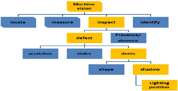
Figure 2.0 K-charts for machine vision
2.1 Machine Vision Flow Process
Machine vision can be categorize in 4 types, measure, locate, inspect and identify. All types of machine vision have same concept but can be applied in different application(SICK IVP 2006). The concept of machine vision system show in figure below:
[image:20.612.157.498.492.643.2]7
As show in figure above, the basic concept or basic operation of machine vision there are 4 step(take image, analyse image, send result and take action) need to complete and this operation will repeat continuously until we stop the operation. In this project for a vision task to detect the dented that occur on the bottom surface of the battery the take image and analyse image are used.
2.1.1 Take Image.
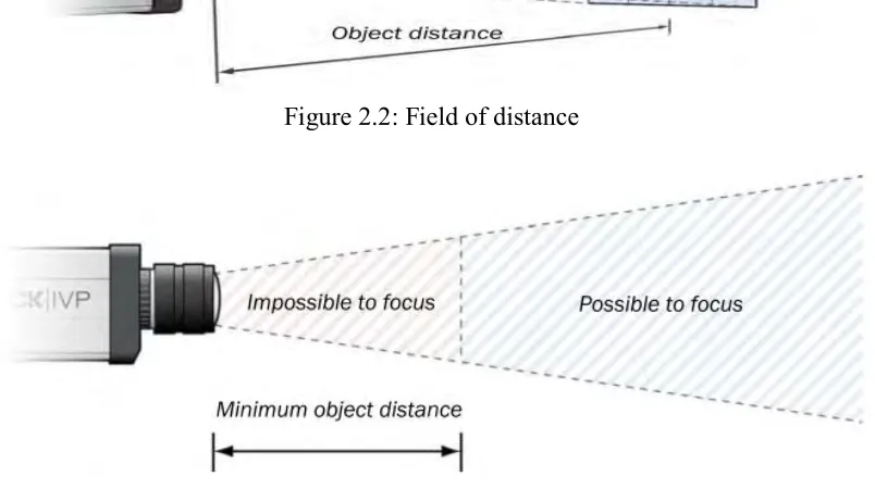
In a machine vision, the imaging is the stage where the images of the target object were created. To get the high quality of image that been capture are the goal of this stage(SICK IVP 2006). to get the best quality image of target/object there are few thing need to be consider:
I. Field of view (FOV).
II. Working distance and resolution. III. Depth of field (DOF).
8
[image:22.612.129.531.127.352.2]Figure 2.2: Field of distance
Figure 2.3: Depth of field.
2.1.2 Image Processing
9
used 2D image or 3D image to as an input to perform image processing stage which will produce an images as an output(Processing & January 2012).
In a computer graphic, there are two types of computer graphic which is raster and vector. Raster is a rectangular small grid of pixel and each pixel is assigned its position(Gonzalez & Woods 2009) and colour in the image and the more the pixel the image will be more accurate(Inglot & Technology 2012). Vector graphical are not in form of pixel like raster but the image files size are smaller than the raster(Inglot & Technology 2012).
In image processing, to analyse the input or the image a method is required to do so. There are many types of method to analyse image and in this chapter, there are few of the method were cover there are:
I. Image processing. II. Image segmentation. III. Image analysis.
2.1.2.1 Image Enhancement
The aim of image processing is to enhance the visual appearance of the image and to improve the manipulation of dataset(Luboz & Dr F Bello (Dept. of Biosurgery) 2012). The image that produce directly using camera may have some issue within the pictures taken(Processing n.d.), to provide more suitable image for future analysis. This process also includes the magnification, scaling, reduction and noise removal(Rao 2006).
2.1.2.2 Image Segmentation
10
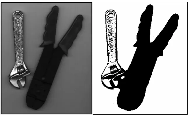
images(Luboz & Dr F Bello (Dept. of Biosurgery) 2012). Thresholding technique are use in image segmentation(Rao 2006).
[image:24.612.202.526.295.493.2]Threshold technique creates binary images from grey level one by truing all pixel below some threshold to zero and all pixel about the threshold to zero(Segmentation & The n.d.). In thresholding there are 2 types of algorithm used in thresholding the first one is local, local algorithm is a threshold surface that is function on the image domain(Kind n.d.). The other types of algorithm is global threshold, this algorithm is a single threshold for all the image pixel is used.(Unknown 2008)
Figure 2.4: Image with threshold technique.