UNIVERSITI TEKNIKAL MALAYSIA MELAKA
VEHICLE TRACKING & LOCKING SYSTEM
USING GLOBAL POSITIONING SYSTEM (GPS)
AND GLOBAL SYSTEM MOBILE (GSM)
This report is submitted in accordance with the requirement of Universiti Teknikal Malaysia Melaka (UTeM) for the Bachelor of Electronic
Engineering Technology (Industrial Electronics) with Honours
by
MOHAMAD FADHLAN BIN AHMAD LOTHFY
B071210289
900222075045
FACULTY OF ENGINEERING TECHNOLOGY
i
DECLARATION
I hereby, declare that this thesis titled “Vehicle Tracking & Locking System Using Global Positioning System (GPS) and Global System Mobile (GSM)” is the result of my own research paper except as cited in the references.
Signature : ______________________
Name : Mohd Fadhlan Bin Ahmad Lothfy
ii
APPROVAL
This report is submitted to the Faculty of Engineering Technology of UTeM as a partial fulfillment of the requirements for the degree of Bachelor of Engineering Technology (Industrial Electronics) with (Hons.). The member of the supervisory is as follow:
……… (NURULHALIM BIN HASSIM)
iii
ABSTRAK
Projek ini adalah mengenai reka bentuk dan pelaksanaan mengesan dan mematikan enjin kenderaan dengan menggunakan Global Positioning System (GPS) dan Global System Mobile (GSM). Ia terdiri daripada integrasi antara penerima GPS, mikropengawal dan modul GSM. Kombinasi teknologi-teknologi ini akan menghasilkan sistem pengesanan. Satu sistem pengesanan menggabungkan dua sistem yang diselaraskan oleh pengawal penerima GPS dan dikawal oleh pengguna menggunakan arahan melalui modul GSM sebagai pemancar dan penerima data. Projek ini juga boleh dibahagi kepada dua bahagian utama iaitu kerja tangan atau perkakasan dan perisian komputer. Pembangunan pekakasan termasuklah GPS, sambungan pendawaian mikropengawal dan integrasinya dengan modul GSM. Pembangunan perisian termasuklah membangunkan kod sumber pengawal mikro dan perintah mesej GSM. Apabila projek ini selesai, seorang pengguna boleh menggunakan pesanan ringkas (SMS) untuk menghubungi dan mengenal pasti lokasi kenderaan apabila dicuri dengan menggunakan alat terkini ini.
iv
ABSTRACT
This project is about the design and implementation of a Vehicle Tracking System using Global Positioning System (GPS) and Global System Mobile (GSM). It comprises of integration between a GPS receiver, a microcontroller and a GSM module. This combination of technologies will produce a tracking system. This tracking system integrates two systems which are the coordinates extracted from the GPS receiver and control capability using command through the GSM module. This project can be divided into two main parts which are hardware and software. The hardware includes the GPS, the microcontroller wiring connection and its integration with the GSM module. The software includes developing the microcontroller source code and GSM message command. For the end result, a user can use short messaging system (SMS) from their phone to contact and identify the location if the vehicle is stolen.
v
ACKNOWLEDGEMENT
Alhamdulillah, most grateful to Almighty ALLAH S.W.T. for blessing me with good health and providing ideas in completing this project successfully.
First of all, I would like to thank Encik Nurulhalim Bin Hassim as my supervisor during this Projek Sarjana Muda (PSM). He gave support and assistance to me, especially the exposure of the C language programming process. Without him, I was facing a lot of problem in completing this project.
I would also like to thank to my Universiti Teknikal Malaysia Melaka for providing this great opportunity and ample time for me to have my final year project completed within a year. Thanks for this precious time and helpful guidance. Honestly, it is the most valuable experience for me to explore and expose myself to the real engineering fields which demands for equal depth in knowledge and management skills.
Besides that, lots of love for my family especially my father Ahmad Lothfy Bin Mohd Idris for giving continuous supports throughout this four years. To my siblings who are always there by my side to encourage, advice and support me during this entire project.
Lastly, I would like to thank all of my colleagues for being supportive, positive minded and contributed a lot of ideas during my academic pursuits.
vi
TABLE OF CONTENTS
Declaration... i
Approval... ii
Abstrak... iii
Abstract...iv
Acknowledgement... v
Table of contents... vi
List of tables... ix
List of figures x List Abbreviations, Symbols and Nomenclatures... xiii
CHAPTER 1: INTRODUCTION...1
1.1. Project Background...1
1.2. Problem Statement...2
1.3. Objective...3
1.4. Project Scope...3
CHAPTER 2: LITERATURE REVIEW...4
2.1. Overview...4
2.2. Background of Tracking Device...4
2.3. Global Positioning System (GPS)...5
2.3.1.
GPS Background Information...52.3.2.
Longitude and Latitude Co-Ordinate System...62.3.3.
GPS Signal Structure...7vii
2.4. Global System Mobile (GSM)...10
2.4.1.
GSM Background Information...102.4.2.
GSM Standard Operation...112.4.3.
GSM Modems...12CHAPTER 3: METHODOLOGY...14
3.1. Overall Project Structure...14
3.2. Expected Result...16
3.3. Project Block Diagram...17
3.4. SKM53 GPS Starter Kit...18
3.4.1.
General Description...183.4.2.
Mechanical Specification...203.5. SKGPS-53 Module Starter Kit...21
3.5.1.
General Description...213.5.2.
Product Layout...223.6. Flowchart Process...24
3.7. GSM Modem...26
3.8. MAX232...26
CAPTER 4: RESULT AND DISCUSSION...28
4.1. Discussion...28
4.2. Hardware...29
4.2.1 Circuit Diagram...29
4.2.2 Single Relay Module...33
4.2.3 Single Relay Module...35
4.3. Software...37
4.4. Analysis...38
4.5. Flowchart GSM Coding...43
viii
CHAPTER 5: CONCLUSION AND FUTURE
RECOMMENDATION...46
5.1. Conclusion...46
5.2. Future Recommendation...47
REFERENCE...48
APPENDIX...49
ix
LIST OF TABLES
2.1 GSM Bands information by country 12
3.1 Antenna specification in SKM53 module 18
3.2 SKM53 pin description 19
3.3 The description of component in SKGPS-53 23
4.1 Technical specs Arduino Uno 31
x
LIST OF FIGURES
2.1 The Earth Divided into Longitude and Latitude 6
2.2 Biphase Modulation of GPS signal 8
2.3 Three Segments of GPS 9
2.4 GSM World Coverage Map and GSM Country 11
3.1 The progress from the beginning of the thesis 15
3.2 The block diagram for the Arduino Uno 17
3.3 Actual view of SKM GPS starter kit 18
3.4 SKM53 pin package 19
3.5 Top View of SKM53 20
3.6 Vertical view of SKM53 20
3.7 Horizontal view of SKM53 20
3.8 Actual view of SKGPS-53 module starter kit 21
3.9 SKGPS-53 layout 22
3.10 The process flow of the Tracking Device to the user 25
3.11 GSM module 26
xi
LIST OF ABBREVIATIONS, SYMBOLS
AND NOMENCLATURE
BPSK - Bi-Phase Shift Keying
CDMA - Code Division Multiple Access
CEPT - European Conference of Postal and Telecommunication Administrations
DOD - Department of Defense EFR - Enhanced Full Rate
FOC - Full Operational Capability GPS - Global Positioning System GSM - Global System Mobile IOC - Initial Operational Capability LPC - Linear Predictive Coding
ME - Mobile Equipment
PCB - Printed Circuit Board
SPAD - Suruhanjaya Pengangkutan Awan Darat SIM - Subscriber Identity Module
SMS - Short Message Service
UMTS - Universal Mobile Telecommunication System USB - Universal Serial Bus
1
CHAPTER 1
INTRODUCTION
1.1 Project Background
A vehicle tracking and locking system consists of an electronic device installed on a vehicle so that it can be tracked by its owner or a third-party for its position. Most of the vehicle tracking system uses Global Positioning System (GPS) to get an accurate reading of the vehicle position. Communication components such as cellular Global System Mobile (GSM) and satellite transmitter will be combined to transmit the vehicle’s position to the remote user. Vehicle’s location information can also be sent to the user’s mobile phone.
Vehicle tracking and locking systems are commonly used by fleet operators for fleet management functions such as routing, dispatching, on-board information display and security. Other applications include monitoring driving behavior, such as an employer monitoring an employee, or a parent monitoring a teenaged driver. Vehicle tracking systems are also popular in consumer vehicles as a theft prevention and retrieval device. The police can simply follow the signal emitted by the tracking system and locate the stolen vehicle. When used as a security system, a Vehicle Tracking System may serve as either an addition to or replacement for a traditional Car alarm. The existence of vehicle tracking device can then be used to reduce the insurance cost, because the loss-risk of the vehicle installed with this system drops significantly.
2
closely monitor movement and operating status. Users can also know where their vehicle is when other user or thief are using their vehicle.
1.2 Problem Statement
The main reason for the proposal of this project is to find a cost-effective, reliable and accurate vehicle tracking device. When vehicles were spread out all over, the user often found it difficult to keep track of what was happening. They require some type of system to determine where each vehicle was at any given time and for how long it has travelled. There is also the need for tracking when an owner is trying to locate a lost vehicle.
GSM and GPS based tracking system will provide effective, real time vehicle location reporting. A GPS- GSM based tracking system will inform where the vehicle is and where it has been, and for how long it has been at that location. The system uses geographic position and time information from the Global Positioning Satellites. The On-Board vehicle module consists of a GPS receiver and a GSM modem.
During vehicle motion, its real-time parameters such as location are reported by SMS message. The system takes advantage of wireless technology in providing powerful transportation management. The use of GSM and GPS technologies allows the system to track the vehicle and to provide the most up to date information about the location of the vehicle.
We can also use it to lock the engine and stop the vehicle. As an example, this system also can also be used to stop the vehicle when the user inserted a wrong password into this system. It could also be used as a valuable tool to detect vehicle location within a short period of time.
3
1.3 Objective
The objective of this project is to design and develop a Vehicle Tracking System using GPS and GSM Technologies. This can be divided into 3 areas:
I. To study and investigate the basic operation of the GPS module and GSM module. II. To design a vehicle tracking and vehicle locking system.
III.To develop the hardware and software for a vehicle tracking and locking system.
1.4 Project Scope
The tracking device consists of the GPS, the GSM modem and the microcontroller. Location name GPS coordinate values are stored in the microcontroller. As soon as the GSM modem receives SMS request for location, the microcontroller checks the GPS ready and sent it to the user as an SMS text using GSM modem. Furthe service enhancements like breakdown alert can be integrated into the proposed system in a cost effective manner.
4
CHAPTER 2
LITERATURE REVIEW
2.1 Overview
This thesis relies heavily on the use of both GPS and GSM. This chapter will begin with an overview of the Global Positioning System explaining about the structure of GPS and the characteristics of GPS. Furthermore, details about the longitude and latitude and how to understand about the location tracking device will be explored.
2.2 Background of Tracking Device
For a long time in history, people has been searching for accurate navigation and positioning methods to determine their location and destinations. The Global Positioning System (GPS) is the best achievement in this search for precise positioning. Though originally intended for military use, GPS has been found to be useful in many civilian applications including surveying and navigation, thus exceeding its original intended purpose. The United States Department of Defence runs this freely available and highly accurate positioning system. This section will provide an overview of GPS and the longitude/latitude co-ordinate system used in this thesis.
5
2.3 Global Positioning System (GPS)
2.3.1 GPS Background Information
The GPS System was created and realized by the American Department of Defense (DOD) and was originally based on and run with 24 satellites (21 satellites being required and 3 satellites as replacement). Nowadays, about 30 active satellites orbit the earth at a distance of 20200 km (Hoffman-Wellenhof, B, H. Lichtenegger and J. Collins (2001).
GPS satellites transmit signals which enables a GPS receiver to extract its location, if it is positioned on the surface of the earth, in the earth atmosphere or in a low orbit. GPS is being used in aviation, nautical navigation and for determing the orientation of shore. The GPS signal can be used without a fee by any person in possession of a GPS receiver. Furthermore, it is used in land surveying and other applications where the determination of the exact position is required. At first only 18 satellites were in operation. In 1988 the number of satellites is raised to 24, as the functionality is not satisfactory with only 18 satellites (Thuong Le-Tien, Vietnam in 2010).
The first Block I satellite carried sensors to detect atomic explosions. This satellite is meant to control the abidance of the agreement of 1963 between the USA and the Soviet Union to refrain from any nuclear tests on the earth, submarine or in space. When a civilian airplane of the Korean Airline (Flight 007) was shot down after it had gone lost over Soviet territory, it was decided to allow the civilian use of the GPS system. In 1986, the accident of the space shuttle "Challenger" meant a drawback for the GPS program, as the space shuttles were supposed to transport Block II GPS satellites to their orbit. Finally the operators of the program reverted to the Delta rockets which were intended for the satellite deployment in the first place.
6
in 1993 (Thor Hogan, Vic Villhard 2004, p. 12). In the same year it was decided to authorize the world wide free of charge usage for civilian.
The last Block II satellite completed the satellite constellation in 1994. Full Operational Capability (FOC) was announced the following year. In the year 2000, final deactivation of the selective availability was done and therefore improving the accuracy for civilian users from about 100 m to 20 m resolution.
2.3.2 Longitude and Latitude Co-Ordinate System
[image:18.612.116.558.465.687.2]The location of any point on a planar surface can be fully described by both a horizontal and a vertical co-ordinate. Had the earth been truly flat and rectangular as it had been perceived in the past, a simple equally spaced grid system could be used to describe any location on earth. However, the earth is neither flat nor rectangular. It is not even a perfect sphere. The fact of the matter is the earth is an oblate ellipsoid, a slightly egg shaped sphere. A grid-like system of latitudes and longitudes was devised to describe precise locations on earth. Both latitude and longitude are measured in terms of degrees, (°). Figure 2.1 shows a map of the earth including basic longitude and latitude information.
Figure 2.1: The earth divided into Longitude and Latitude.
7
Latitudes can be described as lines that circle the earth parallel to the equator, the line that equally divides the earth into a Northern and Southern hemisphere. Degrees of latitude are numbered from 0° to 90° North and South. Zero degrees in latitude is the location of the equator. Ninety degrees North and South is the location of the North and South poles respectively. Each degree of latitude is approximately equal to 111 km, this variation is cause by the ellipsoid shape of the earth.
Longitudes can be best described as lines that circle the earth and converge at both the North and South poles. Degrees of longitude are numbered from 0° to 180° East and West. Zero degrees in longitude is located at Greenwich, England. The East and West degrees meet at 180°, and define the International Date Line. At the equator, a degree of longitude is approximately equal to 111 km. As the latitude increases, longitudinal degrees decrease in distance until they converge at one of the earth's poles.
2.3.3 GPS Signal Structure
8
[image:20.612.117.544.97.282.2]
Figure 2.2: Biphase Modulation of GPS signal.
Since the CDMA signals of a system use the same carrier frequency, there is a greater probability of interference among the signals. This effect is especially significant when strong and weak signals are mixed together. Sometimes during the acquisition process, a cross-correlation peak of a strong signal may be stronger than the desired peak of a weak signal.
2.3.4 Three Segments of GPS
The three segments of GPS are the space, control, and user.
• Space Segment — Satellites orbiting the earth
The space segment consists of 29 satellites circling the earth every 12 hours at 12,000 miles in altitude. This high altitude allows the signals to cover a greater area. The satellites are arranged in their orbits so a GPS receiver on earth can receive a signal from at least four satellites at any given time. Each satellite contains several atomic clocks. The satellites transmit low radio signals with a unique code on different frequencies, allowing the GPS receiver to identify the signals. The main purpose of these coded signals is to allow the GPS receiver to calculate travel time of the radio
9
signal from the satellite to the receiver. The travel time multiplied by the speed of light equals the distance from the satellite to the GPS receiver.
• Control Segment — The control and monitoring stations
The control segment tracks the satellites and then provides them with corrected orbital and time information. The control segment consists of five unmanned monitor stations and one Master Control Station. The five unmanned stations monitor GPS satellite signals and then send that information to the Master Control Station where anomalies are corrected and sent back to the GPS satellites through ground antennas.
• User Segment — The GPS receivers owned by civilians and military The user segment consists of the users and their GPS receivers. The number of simultaneous users is limitless.
[image:21.612.154.439.356.529.2]
10
2.4 Global System Mobile (GSM)
2.4.1 GSM Background Information
The specification of the Global System for Mobile (GSM) communication began in 1982 with the formation of the Groupe Special Mobile (GSM) by the European Conference of Postal and Telecommunication Administrations (CEPT). In 1989 GSM became Technical Committee of ETSI, the newly founded European Telecommunication Standards Institute. This allowed the industry to take a more active role in the standardisation process though “direct” participation. They are also responsible for the Universal Mobile Telecommunication System (UMTS).
GSM offers the user the possibility to roam across networks and national boundaries. A roaming agreement between the two operators is the only real prerequisite. Though the implications of roaming for network management and billing procedures are manifold, one could, from a security point of view, think of the foreign network as a remote part of the subscriber home network. The data needed for checking the authenticity of a user are generated by the (visited) network. It is then handled locally by the Visitor Location Register (VLR) where the (roaming) subscriber is temporarily resisted (Springer-Verlag Berlin Heidelberg, 1998).
11
2.4.2 GSM Standard Operation
[image:23.612.114.575.259.483.2]GSM is a cellular network, which means that mobile phones connect to it by searching for cells in the immediate vicinity. GSM networks operate in four different frequency ranges. Most GSM networks operate in the 900 MHz or 1800 MHz bands. Some countries in the Americas (including Canada and the United States) use the 850 MHz and 1900 MHz bands because the 900 and 1800 MHz frequency bands were already allocated (World Time Zone, GSM World Coverage Map, 1999).
Figure 2.4: GSM World Coverage Map and GSM Country.
GSM has used a variety of voice codecs to squeeze 3.1 kHz audio into between 5.6 and 13 kbit/s. Originally, two codecs, named after the types of data channel they were allocated, were used, called Half Rate (5.6 kbit/s) and Full Rate (13 kbit/s). These used a system based on linear predictive coding (LPC). In addition to being efficient with bitrates, these codecs also made it easier to identify more important parts of the audio, allowing the air interface layer to prioritize and better protect these parts of the signal. GSM was further enhanced in 1997 with the Enhanced Full Rate (EFR) codec, a 12.2 kbit/s codec that uses a full rate channel.
12
Finally, with the development of UMTS, EFR was refactored into a variable-rate codec called AMR Narrow band, which is high quality and stable against interference when used on full rate channels, and less stable but still relatively high quality when used in good radio conditions on half-rate channels.
[image:24.612.113.544.209.374.2]
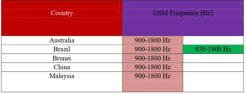
Table 2.1: GSM Bands information by country (May 10, 2014)
Country GSM Frequency (Hz)
Australia 900-1800 Hz
Brazil 900-1800 Hz 850-1900 Hz
Brunei 900-1800 Hz
China 900-1800 Hz
Malaysia 900-1800 Hz
2.4.3 GSM Modems
Global System for Mobile Communications (GSM) modems are specialized types of modems that operate over subscription based wireless networks, similar to a mobile phone. A GSM modem accepts a Subscriber Identity Module (SIM) card, and basically acts like a mobile phone for a computer. Such a modem can even be a dedicated mobile phone that the computer uses for GSM network capabilities.
Traditional modems are attached to computers to allow dial-up connections to other computer systems. A GSM modem operates in a similar fashion, except that it sends and receives data through radio waves rather than a telephone line. This type of modem may be an external device connected via Universal Serial Bus (USB) cable or a serial cable. More commonly, however, it is a small device that plugs directly into the USB port or card slot on a computer or laptop.