UNIVERSITI TEKNIKAL MALAYSIA MELAKA
EXPERIMENTAL EVALUATION OF MULTIFUNCTIONAL
VARIABLE REFRIGERANT FLOW (VRF) SYSTEM IN AN
APPLICATION LABORATORY
This report is submitted in accordance with the requirement of the Universiti Teknikal Malaysia Melaka (UTeM) for the Bachelor of Mechanical Engineering
Technology (Heating, Ventilation and Air Conditioning) with Honours.
by
KOH JIAN YANG
B071410215
940313085085
i
DECLARATION
I hereby, declare that this entitled “Experimental evaluation of multifunctional variable refrigerant flow (VRF) system in an applicational laboratory” is the result of my own research except as cited in reference.
Signature : ...
Name : ………...
ii
APPROVAL
This report is submitted to the Faculty of Engineering Technology of UTeM as one of the requirement for the award of Bachelor’s Degree of Mechanical Engineering Technology (Heating, Ventilation and Air Conditioning) with Honours. The following are the members of supervisory committee:
iii
ABSTRACT
iv
ABSTRAK
v
DEDICATION
vi
ACKNOWLEDGEMENT
First, I would like to express my utmost gratitude and appreciation to my supervisor, Mr. Mohd Faez bin Zainol, who has guided and encouraged me along these two semesters. The supervision and supports from him had help me a lot for the progression of my project.
vii
TABLE OF CONTENT
Contents
DECLARATION ... i
APPROVAL ... ii
ABSTRACT ... iii
ABSTRAK ... iv
DEDICATION ... v
ACKNOWLEDGEMENT ... vi
TABLE OF CONTENT ... vii
LIST OF TABLE ... ix
LIST OF FIGURES ... x
LIST OF ABBREVIATIONS, SYMBOLS AND NOMENCLATURE ... xi
CHAPTER 1 INTRODUCTION ... 1
1.1. Problem Statement and Objective... 1
1.2. Background ... 1
1.3. Equipment ... 3
1.4. Scope ... 3
CHAPTER 2 LITERATURE REVIEW ... 4
2.1. Definition of HVAC ... 4
2.2. VRF SYSTEM ... 5
2.2.1. Operation of VRF system ... 6
2.2.2. Application ... 9
2.3. Cost ... 10
2.4. Design VRF system ... 11
2.5. Case study ... 12
2.6. The advantage of VRF system ... 15
2.7. Coefficient of Performance (COP) ... 15
2.8. Psychrometric chart ... 16
CHAPTER 3 METHODOLOGY ... 18
3.1. Project Planning ... 18
viii
3.2. Research Methodology ... 22
3.2.1. Problem identification ... 22
3.2.2. Objective and scope ... 22
3.2.3. Literature Review ... 22
3.3. Testing method ... 23
3.3.1. Enthalpy potential method ... 23
3.3.2. Testing Requirement ... 24
3.3.2.1. Required Temperature and Airflow rate ... 24
3.3.2.2. Operation Requirement ... 24
3.4. Measurement ... 25
3.4.1. Measurement for indoor unit ... 25
3.5. Purchase of measuring device... 29
3.6. Experiment procedure ... 29
3.7. Data Sheet for Experiment ... 31
CHAPTER 4 RESULT & DISCUSSION ... 34
4.1. Introduction ... 34
4.2. Preparation of experiment ... 34
4.3. Experiment 1: Investigate the excessive cooling capacity... 35
4.4. Experiment 3 with only switch on unit 1 ... 41
4.5. Application and installation of the VRF system in laboratory ... 42
CHAPTER 5 CONCLUSION AND RECOMMENDATION ... 43
5.1. Introduction ... 43
5.2. Summary of research ... 43
5.3. Achievement of objectives... 44
5.4. Limitation of the project ... 44
5.5. Recommendation ... 45
REFERENCE ... 46
ix
LIST OF TABLE
Table 1: Gantt Chart ... 20
Table 2: Parameter for full load test ... 31
Table 3: Parameter for intermediate partial load test ... 32
Table 4: Parameter for lowest partial load test... 32
Table 5: Table for record current reading ... 33
Table 6: The measured value of the first experiment ... 36
Table 7: The density of air at different temperature ... 37
Table 8: The calculated used cooling capacity ... 37
Table 9: The new total cooling capacity used after correction ... 39
Table 10: The cooling capacity used when switch on 3 units only ... 40
x
LIST OF FIGURES
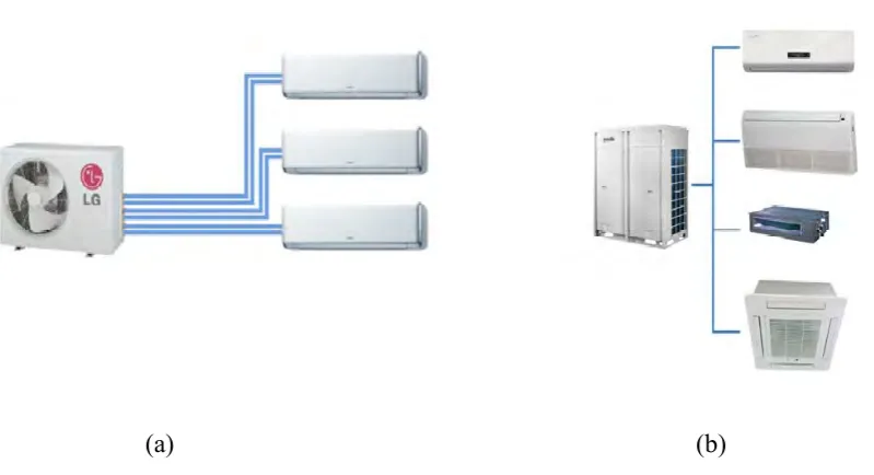
Figure 1: Piping system of conventional multi-split (a) and VRF multi-split (b) ... 7
Figure 2: VRF System with multiple indoor evaporator units. (A. Alahmer, S. Alsaqoor) ... 8
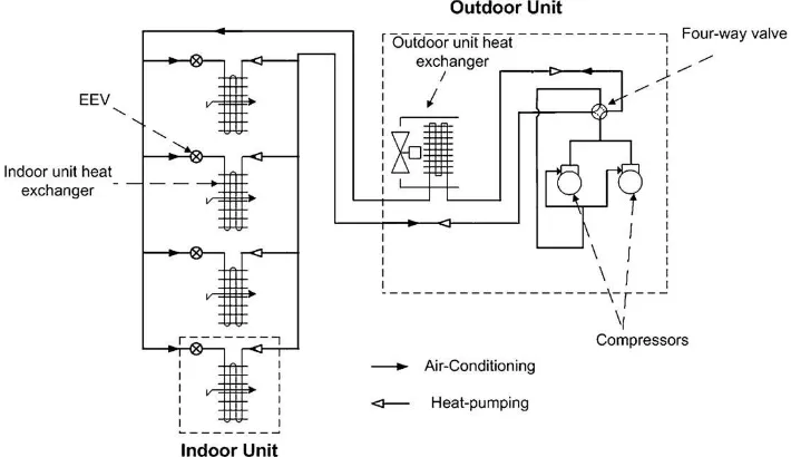
Figure 3: Schematic diagram of a multi-split VRF system having four indoor units. (Tolga N.Aynur) ... 8
Figure 4: The formula for COP (LearnThermo.com) ... 16
Figure 5: Psychrometric chart shows temperature vs. humidity, and can be used to express human thermal comfort, design strategies, and energy requirements for those strategies. (Autodesk) ... 17
Figure 6: Flowchart of the project ... 19
Figure 7: Anemometer (a), Measuring Tape (b), Thermocouple (c) ... 25
Figure 8: Ceiling Concealed type indoor unit (a)and side view (b) ... 26
Figure 9: Ceiling cassette unit ... 26
Figure 10: Ceiling convertible type (a) and its side view (b) and the position to take reading(c) ... 27
Figure 11: Ceiling convertible type (a) and its side view (b) ... 28
Figure 12: Clamp ammeter ... 29
Figure 13: Clamp meter to measure current (left) and thermocouple to measure temperature (right) ... 34
Figure 14: Connect the wire to plug (left) and cut the thermocouple wire to desire length ... 35
Figure 15: Test room and system that used for this project ... 36
Figure 16: The rated cooling capacity of outdoor unit ... 38
Figure 17: The comparison of cooling capacity for each unit in clean and dirty condition ... 39
xi
LIST OF ABBREVIATIONS, SYMBOLS AND NOMENCLATURE
AHRI The Air Conditioning, Heating, and Refrigeration Institute
AHU Air Handler Unit
ASHRAE American Society of Heating, Refrigerating and Air-Conditioning Engineers.
Btu/h British Thermal Unit per hour
COP Coefficient of Performance
COPHP Coefficient of Performance for Heat Pump
COPR Coefficient of Performance for Refrigeration
DC Direct Current
DX Direct Expansion
EEV Electronic expansion valve
HVAC&R Heating, Ventilating, Air Conditioning and Refrigerating
PCM Phase Change Materials
PLR Partial Load ration
SEER Seasonal Energy Efficiency Ratio
SI units International System of Units
STA Separation Tube Assemblies
TES Thermal Energy Storage
VRF Variable Refrigerant Flow
VRV Variable Refrigerant Volume
YDS York Digital Scroll Compressor
ha1 enthalpy of return air
ha2 enthalpy of outlet air
xii
QCi cooling capacity of indoor unit
QCO cooling capacity of the outdoor unit.
Qf air flow rate
QH heat supplied to the cold reservoir.
Ti Initial Temperature
Tf Final Temperature
Va Air Flow Velocity
Vn specific volume of moist air
W Watt
1
CHAPTER 1
INTRODUCTION
1.1.Problem Statement and Objective
The Variable Refrigerant Flow system installed in the laboratory application always facing a problem which is the system is not fully utilized according to its capacity. Thus, the objective of this project is to investigate the effects of excessive cooling capacity on the daily performance usage and total energy consumption was experimentally investigate in the field performance tests. After determine the excessive cooling capacity, the number of indoor unit that able to be added to the system is estimated base on the excessive cooling capacity. The initial cost of the VRF system is normally 20% higher than other system in the same amount capacity. [1] Thus, utilize the VRF system is importance to make the money spend become valuable.
1.2.Background
Air conditioning is a combined process that performs many functions simultaneously. It conditions the air, transports it, and introduces it to the conditioned space. It can provide heating and cooling from its central plant or rooftop units. It also controls and maintains the indoor air quality, sound level, and pressure of the conditioned space to provide good thermal comfort to the occupant of the conditioned space. Air conditioning also used for product processing too to provide clean condition. For example, the manufacturing plant of automotive which using carbon fibre need to have a no-dust working condition.
2 multiple indoor fan coil units which capable of individual zone temperature control by zone temperature control devices and common communications network. [2]
VRF is first introduced in Japan by Daikin in 1982. VRV, variable refrigerant volume is the trademark for Daikin Industries, Ltd for variable refrigerant flow technology. The reason for Daikin to develop VRF is to provide individual control for each zone. Then, this technology had gradually become more popular and reach Euro in 1987. In Japan, VRF system take approximately 50% market share for medium size commercial building’s air conditioning system and one third of the large commercial building. [1]
VRF system is differentiate into two type which are VRF Multi-split system and VRF Heat Recovery Multi-split system. The VRF system used in this project is VRF multi-slit system. A multi-split VRF system is a refrigerant system that has variable refrigerant flow rate with the help of the variable speed compressor and electronic expansion valve located in each indoor unit to match with the cooling load of each indoor unit in order to maintain the temperature and humidity with the set value of each zone. [3] The multi-split VRF system has two types of pipe configuration which are two pipes and three pips and usually two pipe is used for VRF multi-split system and three pipe is for VRF heat recovery system. For two pipe configuration piping system, there is one pipe for high pressure(supply) and other one pipe for low pressure(return). [4]
In other words, VRF system is the larger capacity, more complex version of the ductless multi-split system. Besides that, VRF has can connect to ducted style fan coil units too. VRF technology able to control the amount of refrigerant flow into each indoor unit based on its load. Thus, individual zone control and simultaneous heating and cooling in different zone is easy to achieve in VRF system. [1]
3
1.3.Equipment
The VRF system in the laboratory application is manufacture by YORK and its model number is YDS120B5. YDS means York Digital Scroll Compressor and 120 means the 12 horsepower of input power. This VRF system has 2 compressors, one is fix speed and other one is variable speed compressor and 6 horsepower for each. The refrigerant used is R410a. It is manufactured in 2013. The system is using 2 pipes system to connected to indoor units, one for supply and one for return. The system has variable speed condenser fan too to adjust the fan speed base on requirement. The system has been connected to 5 indoor units with different cooling load.
1.4.Scope
4
CHAPTER 2
LITERATURE REVIEW
This chapter is discussed about evaluative report of information found in the literature which related to my selected area of study. Some definition from several sources, operation of VRF, application and the case study from the other authors about the VRF. Besides, the sources from Internet or library will be used to describe, summarize, evaluate and clarify the method to test the VRF system.
2.1.Definition of HVAC
The term HVAC&R defined as heating, ventilating, air conditioning, and refrigerating. HVAC design system is a sub discipline of mechanical engineering, based on the principle of thermodynamics, fluid mechanic and heat transfer. Air conditioner is a type of HVAC product. The main purpose of air conditioning had invented is to control the indoor air quality to provide good thermal comfort to the occupant in the conditioned space. Air conditioning system is used for the product processing too to provide a clean air that needed for the process.
Based on the working fluid used in the thermal distribution system, HVAC systems can be classified as [5]
a. All air system b. All water system c. Air-water system
d. Unitary refrigerant based system
5 For example, window unit, fan coil unit, split unit, packaged unit, central air conditioner dual duct system and variable refrigerant flow system. [1] The main factors for consideration are climate, client and building configuration. For climate, the 4 seasons country need to use the HVAC system for cooling in summer and heating in winter but heating is unnecessary for country in equator like Malaysia. Client is also a main factor because they control the budget. Building configuration is important because some existing old building might not have enough space to place the chiller plant and ducting system. With the awakening of people on energy saving, producer and researcher have to make great efforts to study and develop various kind of air conditioning system to fulfil the market, and one of the most interesting developed product is the variable refrigerant flow (VRF) system with the variable speed compressor and the electronic expansion valve because of its high demand of energy saving. [9]
2.2.VRF SYSTEM
VRF system is classified into unitary refrigerant based system with direct expansion (DX). [5] This system was first introduced in 1982 by Daikin, which is a Japanese company. [3] In Japan, VRF system take approximately 50% market share for medium size commercial building’s air conditioning system and one third of the large commercial building. [1] The ASHRAE Standard 62 defined a VRF system as ‘‘to ability of HVAC system to regulate and control the amount of refrigerant flow to each of the indoor units/evaporators, then enable to use multiple evaporators of differing capacities and configurations, individualized comfort control, simultaneous heating and cooling in different zones with heat recovery from one zone to another”. [1]
6 The most important moment in development of VRF came in 1990 when Daikin introduced inverter control into its heat pump VRV and its number of supported indoor units increased from four to eight. Inverter capacity control increased system flexibility and efficiency by controlled the compressor speed based on the cooling load and using a more energy efficient direct current(DC) motor. In the next year, a further development was come with the introduction of heat-recovery, extended the following year by fresh-air supply and computerized system management. By 1994, Daikin’s VRV can operate up to 16 indoor units from one outdoor unit. Commercial air-conditioning technology move big step forward in 2003 with Daikin introduce the VRVII — the first VRF system using R410a and available in both pump and heat-recovery formats and many new features. The advantage of R410a is more environmental friendly compare to R22. R410a has lower ozone depletion factor and global warming potential than R22. VRVII represented a considerable advance over earlier systems. The use of a purpose-built inverter-controlled scroll compressor for example, raised COPs to a new level, whilst its DC motor promoted high energy efficiency, particularly in the most frequently used low to mid settings, reducing energy consumption and costs. In 2000, the first VRF system with water-cooled condenser was introduced which help to extended its application. Before that, VRF system only has air-cooled condenser. The water-cooled VRF system suited to both new and existing high-rise commercial buildings or projects lacking roof space or external space for outdoor units or where stringent noise regulations apply. The layout of a water-cooled system allows operation independent of ambient conditions. [10]
2.2.1. Operation of VRF system
7 (a) (b)
8 Figure 2: VRF System with multiple indoor evaporator units. (A. Alahmer, S.
Alsaqoor)
Figure 3: Schematic diagram of a multi-split VRF system having four indoor units. (Tolga N.Aynur)
In the cooling mode, the refrigerant discharged from the compressors enters the outdoor unit heat exchanger which act as condenser to remove heat from refrigerant to the environment for reduce its temperature. Then, the high pressure, low temperature refrigerant is expanded to low pressure by the EEV and enters the indoor unit heat exchanger which act as evaporator to absorb heat from the conditioned air. Then, the low pressure superheated refrigerant returns to the compressors, and finishes the cycle. [13]
[image:21.595.141.496.318.523.2]9 to the indoor air to provide warm air to the conditioned space. Then, the high pressure, low temperature refrigerant is expanded to a low pressure by the EEV. The low pressure, low temperature refrigerant enters the outdoor unit heat exchanger (used as an evaporator). The low pressure superheated refrigerant returns to the compressors, and repeat the cycle again and again. [13]
Generally, the multi-split VRF systems have either two-pipe or three-pipe configurations and they are worked with or without ice thermal storage tanks. The two-pipe (a high-pressure gas two-pipe, a low-pressure liquid two-pipe) multi-split VRF systems are the general ones that can be used for cooling or heating depending on the season. That means it cannot provide heating and cooling at the same time. In the other hand, the three-pipe (a high- pressure gas pipe, a low-pressure gas pipe, and a low pressure liquid pipe) VRF systems has the best efficiency and can provide heating and cooling at the same time with the same outdoor unit. This generally occurs in the winter season in medium-sized to large sized commercial buildings with a substantial core such as computer rooms [4].
VRF system connect multiple indoor units to a common liquid and suction line by using separation tube assemblies (STA) and EEV. STA diverts the common flow of refrigerant to individual evaporator and the amount of refrigerant flow into the indoor unit is controlled by the EEV on each indoor unit. The advantage of this kind of piping are [5]
a. Pipe length of VRF system can up to 150 meters. b. Less copper used
c. Eliminates most duct work d. Quick installation
e. Use less space
2.2.2. Application
10 systems can also be used in luxury single-family homes as well as in condos and multi-family residential buildings [4]. In addition, the historical buildings have benefited from the minimum alterations needed for the addition of a multi-split VRF system because the building layout of the old building is not ready for the ducting system. Retrofit situations can also be good applications for the ductless systems since additional ductwork can be minimized with the multi-split VRF systems compared to ducted systems [4].
In 21st century, high rise building become the main character in a city or town
because in the limited amount of space need to take lots of people. Thus, when design a HVAC system for a high-rise building, use the minimum of space, low maintenance cost, availability of individual control, high flexibility and reliability is very important. VRF system can satisfy almost all of the requirements. Most of the VRF system is working in ductless eliminate the needs of the water pipe to transfer the chilled water through the building. It only need refrigerant pipe which is very small in size compare to the water pipe to supply chilled water. After that, VRF multi-split system also can provide individual zone control which is difficult to do in chilled water system. The using of VRF system in high rise building can help reduce the use of space for HVAC system means save cost because the price of land is very expensive. VRF system predicted to save nearly 50% of energy compare to average HVAC system in the same amount of life time. [14]
The other application of the VRF system is combined VRF system with thermal energy storage system (TES) to reduce the power consumption. [15] Basically, the TES system can be operated during the on peak thermal load conditions for conserving the average energy consumed by the cooling unit on a per day basis. Of the different types of TES systems available, the latent thermal energy storage system using phase change materials (PCMs) has proven its performance over two decades. [16]
2.3.Cost
multi-11 split system. [1,4] The total costs of the multi-split VRF system were likely to be about 5% to 20% higher than the chilled water systems with comparable capacity and about 30% to 50% more than equivalent capacity single package ducted system with seasonal energy efficiency ratio (SEER) of 13 to 14. The total cost of VRF system is two times more than the packaged unit too. [4] Cassidy and Sweet compared the whole-life costs of four common air conditioning systems (variable air volume with perimeter heating, four-pipe fan-coil units, multi-split VRF, chilled ceilings and passive beams with radiant panel perimeter heating) used in a new modern three-storey commercial office building with a gross internal floor area of 6500 m2 for a 25-year operating period. The
whole-life cost analysis showed that, the cheapest to operate is the chilled ceiling, follow by four-pipe fan-coil units and variable air volume system. The most expensive is the VRF system which is 111% more expensive than the chilled ceiling unit. [17] Besides, the multi-split VRF systems do not have any ventilation capability, that’s why additional ventilation systems are necessary, which also increases the cost. [1]
2.4. Design VRF system