by
ANTHONY JOHN THOMPSON FINNEY B.Sc.(Hons.)
submitted in fulfilment of the requirements for the Degree of
Doctor of Philosophy
UNIVERSITY OF TASMANIA HOBART
Frontispiece (reproduced as Plate 6 - 1, Chapter 1) - two
views of a large single crystal of KI 3 .H 20. The dimensions
the best of my knowledge and belief, this thesis contains no copy or paraphrase of material previously published or written by another person, except where reference is made in the text of this thesis.
page
Abstract (iv)
Acknowledgements
(vii) Chapter 1 - The Structure and Stability of Simple 1
Tri-iodides
Chapter 2 - The Theoretical Basis of X-Ray Structural 32 Analysis
Chapter 3 - The Crystallographic Program Suite 50
Chapter 4 - The Refinement of the Structure of NH
4I3 94 Chapter 5 - The Solution of the Structure of RbI
3 115
Chapter 6 - The Solution of the Structure of KI 3 .112 0 135
Chapter 7 Discussion of the Inter-relation of 201 Structure and Stability
Bibliography 255
Appendix A - Programming Details 267
Appendix B - Density Determinations 286
Appendix C - Derivation of the Unit Cell Constants of 292 KI
3.H20
Appendix D - I -3 force constant Calculation 299
THE STRUCTURE AND STABILITY OF SIMPLE TRI-IODIDES
Abstract
In this work the simple tri-iodides are regarded as being those in which the crystal lattice contains only cations, tri-iodide anions and possibly solvate molecules. The alkali metal tri-iodides CsI
3
and KI3.H20 exemplify compounds of this type; polyiodides like the penta-iodide (CH3)4NI5 or the hepta-iodide (C
2H5)4I7' in which it is
' known that the anionic group is made up of I -3 units accompanied by iodine molecules, are not encompassed by this study. In the solid state the simple tri-iodides exhibit a wide range of stability, and the probable causes underlying this range in behaviour are reviewed against existing knowledge concerning the crystalline structure and current models of the anion bonding of these compounds. The presence of solvate molecules in the lattice has a profound effect upon the stability of the simple tri-iodides; also among the unsolvated species there is a range in stability which can be attributed to
differences in the electrostatic environment experienced by the anion. This sensitivity to electrostatic environment is reflected in small differences in the geometric configuration of the anion among the unsolvated tri-iodides as revealed by crystal structure analysis.
As the number of accurately known simple tri-iodide structures is small, the structure of
NH4I3 was refined and the structure of RbI3
and the hydrated species, KI3.H20, were determined by the X-ray cryst- • allographic method. A preliminary to this work, made necessary by the
unusual features.of the only available computing facilities, was the development of a complete integrated suite of crystallographic programs. Using the single crystal X-ray diffraction technique in conjunction with
- this program suite the accuracy with which the geometry of the 1
in
NH4I3 is known was significantly improved. The structural analysis of RbI 3 proved that this compound was isostructural with CsI 3 , as had been anticipated on the basis of the known isomorphism of these two tri-iodides. In the case of KI 3 .H20, the structure differs from that of the unsolvated simple tri-iodides (which all crystallize with unit cells having centrosymmetric orthorhombic symmetry) in that this compound possesses a noncentrosymmetric monoclinic cell. However, both K1
3•H20 and the unsolvated tri-iodides share the same planar structural motif defined by the relative arrangement of cations and anions in the cell.
On the basis of the extended body of structural data made available by the examination of these compounds, it was shown that the stability of the simple tri-iodides can be qualitatively and quantitatively
related to two effects. The first of these is the stabilizing influence of electronic interactions between neighbouring 1
3 groups within the planar structure motif. The second is the destabilizing influence of any asymmetry in the electrostatic field experienced by the terminal atoms of the anion. The stability of the unsolvated species is determined by the balance struck between these two effects. It is suggested that in the case of the solvated simple tri-iodides, the presence of solvate molecules leads to a reduction in the de-stabilizing effect due to crystal field asymmetry, and that for this class of compounds their stability is largely conditioned by the strength of cation-solvate and solvate-solvate interactions.
Acknowledgements
It is a pleasure to acknowledge my indebtedness to my
supervisor, Dr. G.H. Cheesman; firstly, for introducing me to the problems of polyhalogen chemistry, and secondly for his sustained encouragement, advice and valued criticism throughout the extended period occupied by this work. Thanks are also due to my colleague, Mr. W.F. Donovan, for many useful discussions concerning the
development of the crystallographic program suite in particular, and the art of X-ray structural analysis in general. At the same time I would like to acknowledge helpful discussions held with past and present members of the staff of the Chemistry Department of the University of Tasmania, and also to thank Professor H. Bloom for making it possible for this project to be undertaken in this Department.
I am also indebted to the staff of the Hydro-University Computing Centre; in particular to its Director, Mr. J. Boothroyd, for his deep interest in the special problems of crystallographic computer programming. In this connection I would like to acknowledge the hospitality and assistance given to me by Dr. B. Gatehouse and the members of the crystallographic group at the Department of Chemistry, Monash University.
Lastly, I gratefully acknowledge the understanding support given
throughout this project by my wife and children; this work is
• respectfully dedicated to them in recognition of a display of
tolerance beyond the call of family duty.
Chapter 1 - The Structure and Stability of Simple Tri-iodides
page
1 - 1 Introduction and Historical Perspective 2
1 - 2 Polyiodide Stability
1 - 3 Stability and Solvation 8
1 - 4 Polyiodide Structural Data 15
1 - 4 - 1 CsI
3 15
1 - 4 - 2 NH 4I3
15 1 - 4 - 3 (C
2H5)4NI3 15
1 - 4 - 4 (C
6H5)4AsI3
16 1 - 4 - 5 (C
5H5)2FeI3
17 1 - 4 - 6 CsI
4 17
1 - 4 - 7 (CH
3)4NI5
18 1 - 4 - 8 (C
2H5)4NI7
18 1 - 4 - 9 (CH
3)4NI9
20 1 - 4 - 10 K
2I4.6(CH3CONHCH3)
22 1 - 4 11 HI
3.2(C6H5CONH2)
22 1 - 4 - 12 HI
5.2(C10H1302N)
23
1 - 5 Polyiodide Bonding in relation to Stability and 24 Structure
would interact with halides to form a complex species were made from the beginnings of modern chemistry. In 1814 Gay-Lussac made the following comment -
"Att
06the hydADiodates
(iodides in modern terminology)have
The ptopeAty
o6 dissotving iodine abundantty, thekeby becoming
At/tong/4 cotouted teddizh-btown. But
they
onty
netain
the
iodine
with
yeAy
ieebte 6o)tce; 6o/t. they giye it up
on boiting
ot
evaponation in
ait; moteovet,
the
iodine doeo
not change the
neuttatity o6 the hydtoiodates
(iodides)and
the teddi.sh-bitown
cotomation o the tiquid,
simitak to that
o6 othet
401 .&0n4 06
iodine, a new
p.'wo o
the Oebteness o the
combination'
(Gay-Lussac [18141).
In 1819 Pelletier and Caventou [1819] described a new compound, which they named 'hydroiodure iodure', formed by the addition of iodine to strychnine. This compound was in all probability strychnine polyiodide, C 2 0 230 2 N 2 I 3 . Their work, published in
Annates
de
chimie et
de
physique,
has some significance as it is the first report of a polyhalogen complex in the literature. The first account of a polyhalogen complex of an inorganic cation was published in 1839 in a series of four papers by Filhol [1839a, 1839b, 1839c, 1839d] in which he described the preparation and reactions of the compound potassium tetrachloroiodate, KIC1 4 . In 1860 Baudrimontobserved that the solubility of iodine increased with increasing strength of the potassium iodide solution, and conversely that free iodine was precipitated when such strong solutions were diluted. They regarded
this as proof that true compound formation did not take place.
Tilden [1850] and Jorgensen [1856a] subsequently reported a number of new solid alkaloid tri-iodides; and Jorgensen [1856b], in seeking an
explanation for the enhanced solubility of iodine in solutions of potassium iodide, advanced the hypothesis that this behaviour (and the results of the extraction experiments) could be explained by assuming partial dissociation of the complex in solution. As a consequence, any
removal of iodine from the solution would result in a shift of the
equilibrium, leading to the eventual complete dissociation of the compound.
The reservations held concerning the existence of the tri-iodide species were at least partially removed by Johnson's report in 1877 of the preparation of crystalline potassium tri-iodide by the slow evapora-tion of an iodine saturated soluevapora-tion of potassium iodide, and his further description in 1878 (Johnson [1878]) of the preparation by the same
technique of ammonium tri-iodide. • The determination of the freezing point depression of potassium iodide solutions by iodine made in 1890 by Noyes and Le Blanc [1890] showed that in solution the complex carried only one negative charge, but did not allow the exact formula of the anionic species to be determined. The two lines of evidence for the existence of the I
-3 complex, the solution studies on the one hand and the preparative work on the other, were finally drawn together by Jakowkin
of compounds is now voluminous, and a number of reviews in this field have been published (Grinell-Jones [1930], Cremer and Duncan [1931a, 1931b, 1932, 1933], Gmelin [1933], Sidgwick [1950], Wiebenga
et
aii
[1961], Rundle [1963], Stepinet atii
[1965]and most recently Popov [1967]).The generalized formula
XpVqZA. may be used to represent poly-halogen ions, X, V and Z denoting either identical or different poly-halogen atoms. The sum
p+q+k
is in most cases an odd number equal to or less than nine (the 'odd-number rule'). The majority of polyhalogen ions known are anionic, and in the past these have been described as addition products resulting from the action of a halide ion acting as a Lewis base upon a halogen or interhalogen molecule or molecules behaving as Lewis acids. However, cationic polyhalogen species have recently been reported, and these cannot be accommodated in this simple scheme. The cationic polyhalogens have been reviewed in detail elsewhere (Gillespie and Morton [1971], and as they stand outside the scope of this work, they will not be considered further.With the possible exception of the polyastatides (Appelman [19601), the polyiodides - with which this study is primarily concerned - are the most stable representatives of the class of polyhalide complexes. It is interesting to note that apart from the polybromide Mr6.1.5 H20
(Harris [1932]), all the examples of the breakdown of the 'odd-number rule' are found among the polyiodides. The first of these to be reported,
CsI4' was accepted with considerable reluctance. This was
only completely dispelled when an X-ray structural determination
(Havinga
et
aii
[1954]) demonstrated that the compound should be more properly formulated as the dimerCs2I8' the 18 anion being interpreted
- . as a loose assemblage of 1
3 ions and iodine molecules. That this
[1942] that
Cs2I8 is diamagnetic. By analogy, the diamagnetic polyiodide LiI
4.4H20 reported by Cheesman and Nunn [1964] may perhaps be expected to have the formula [Li(H 2 0) 4 ] 2 I 8 . In the case of the hydrated sodium polyiodides NaI
4.2H20 and NaI2.3H20 (Cheesman
et
a(i
[1940]), these may equally well be regarded as double salts(NaI
3. .NaI5 .4H2 0 and NaI.NaI3.6H20). However it must be noted that .
Briggs
et
atii
[1941] have raised doubts concerning the precise formu-lation of these species, and these may not be resolved until structural determinations have been tarried out. In any event, the 'odd-number- rule' must evidently be treated with caution, as polyiodide formation exhibits a variety of phenomena which require something more than simple valence considerations for their explanation.1 - 2 Polyiodide Stability
All polyiodides dissociate on exposure to the atmosphere to the iodide and iodine (plus solvent, if solvated) under normal conditions of temperature and pressure. For some, like KI
3.H20 for example, this process is very rapid, going to completion in a matter of minutes. For others, of which (CH3)4NI3 affords an example, decomposition is very slow and can only be detected after the passage of some weeks. The compounds can be stored indefinitely at equilibrium with their dissoc-iation products in sealed containers.
A measure of the stability of the Polyiodides can be gained from the data of Ephraim [1917], who measured the temperature at which the dissociation pressure of iodine over the polyiodides of caesium and
rubidium reached one atmosphere. He found this temperature to be 250 ° C and 192 ° C respectively. His dissociation pressure/temperature data for these two compounds is represented as a ln
p
vousuz
1/T°K
plot inCD (V
CD CN
CD
01
CD
rt-
Figure 1 - 1, in
p
VeluSUA1/T°K
for CsI 3 , RbI 3Another and perhaps more precise measure of the relative stability of the polyiodides was devised by Cremer and Duncan [1931b]. Poly- halide salts were suspended in carbon tetrachloride, in which solvent both the parent halide and the derived polyhalogen compound are insol-uble. The determination of free halogen in solution after equilibra-tion gave an indicaequilibra-tion of the stability of the polyhalide in quesequilibra-tion. In Table 1 - 2 their results for the tri-iodide species are presented.
Table 1 - 1
Concentration of halogen in equilibrated polyhalide salt - CC14 System
Cation Concentration (eq/litre)
Cs 0.00075
Rb 0.0059
NH
4 0.0120
The results presented in Table 1 - 1 indicate the instability of the polyiodides under normal conditions of temperature and pressure. They also show that the size of the cation has a pronounced effect on the stability of the tri-iodide species, and Cremer and Duncan [1931b] have shown that a parallel trend is exhibited by the mixed trihalides IBr2' IC1
2 and IBrC1 . It appears that this characteristic reflects
both the weakness of the bonding within the anionic polyiodide group and its sensitivity to its immediate environment. For example; caesium tri-iodide,
CsI3' is easily prepared from aqueous solution as
chemical measurements for the reaction:
MI (4 ) + 1
2 (4 ) = MI3 (4 )
In Figure 1 - 2 the values of AG° and AH° determined by Topol [1967] at 25°C for this reaction for caesium, rubidium and ammonium have been plotted against r
+, the cation radius. Here r+ is taken (Cotton and Wilkinson [1972]) as 0.97, 1.33, 1.43, 1.48, and 1.68A ° for Na+,
+ NH
4' Rb
+
and Cs+ respectively. From the trend of the points plotted in this Figure, it can be seen that the thermodynamic data are in
complete accordance with the results of the vapour pressure and solution studies. Extrapolation of the trend indicates that in the case of sodium it is highly probable that both AG° and AH° are positive, while in the potassium system the values are probably close to zero. Such a conclusion is not at variance with the observation that unsolvated potassium and sodium polyiodides are not formed at 25°C. As the same
study reports AG° to be only slightly dependent on temperature in these systems, it is not likely that unsolvated forms would be stable at reduced temperatures.
The effect of cation size on polyiodide Stability is also reflected in the behaviour of the larger polyiodide ions; for example, the large anion I; does not form a solid unsolvated compound with the caesium cation. However, it can form stable unsolvated crystalline compounds
• with, large singly-charged organic cations; as for example With the
tetramethylammonium and trimethylphenylammonium cations.
1 - 3 Stability and Solvation
c■
t0 •
0 •
+
PHN-0
c18-4
e:-
EN-4
1
CD
tp
CD CD
N--
d ,-.:. < 74 c
■
i . .4
rn
1 I
M y
<1
Figure 1 - 2, AG ° and AH ° versus r+ for CsI 3 , Rb1 and NH4 I 3 3
compounds. The contrasting histories of ammonium and potassium tri-iodide are illustrative of the problems which have been encountered in this field. Both these compounds were first described by Johnson [1877, 1878]. The existence of ammonium tri-iodide was generally accepted, but the potassium polyiodide became, for more than half a century, the
subject of much controversy and some acrimonious debate (Bancroft
et atii
[1931]). In 1931 the question of this compound's existence was finally resolved by Grace [1931]. He recognized the possibility of hydration, and by a careful phase study of the system KI-1 2 -H 20 at 0 ° C clearly demonstrated the formation of the hydrate KI 3 .H 2 0 at this temperature. In this work Grace made a key contribution to the understanding of poly-halide chemistry, as he showed that many of the anomalous and previously puzzling properties of polyhalides could be understood if the hypothesis of solvation were accepted (Grace [1933]). In view of the long period which elapsed between the initial description and final confirmation of the existence of a tri-iodide of potassium, in contrast to the ammonium compound, it is perhaps ironic that as a result of a subsequent detailed study of the NH 4 1-1 2 -H 20 system, Briggs
et atii
[1940] demonstrated the existence of a previously unsuspected ammonium tri-iodide trihydrate. This hydrated compound melted incongruently at 7 ° C to give the unsolvated form discovered by Johnson [1878].Water is not the only molecule which is known to stabilize poly- iodide structures. In fact', a considerable range of organic molecules . are known which will also perform this function. It includes benzene,
TABLE 1 - 2
Polyiodides crystallizing with organic solvate molecules
Compound Reference
2CsI
9 .3(benzene)
HI
3.4(benzonitrile)
LiI
3.4(benzonitrile)
NaI
3.2(benzonitrile)
KI
3.2(benzonitrile)
K
2I4.6(N-methylacetamide)
HI
3.2(benzamide)
NaI
3.3(benzamide)
NaI
5.4(diethyloxalate)
KI
3.2(diethylmethylorthoformate)
CaI
6.6H20.6(succinimide)
Foote & Bradley (1933)
Martin (1932)
Toman, Honzl & Jecny (1965)
Moore & Thomas (1914)
Reddy, Knox & Robin (1963)
Skrabal & Flach (1919)
It
Snook (1967)
HI
5.2(phenacetin) Emery (1926)
.2(trephenin).
HI
3.2(methacetin)
2HI
5 .3(antipyrine) .
HI
4.1(pyramidone)
On the basis of these data it is possible to make the following generalization: within the family of polyiodide compounds the require-ment for some solvate molecule to stabilize the polyiodide anion suffi-ciently to allow the formation of solid crystalline compounds under normal laboratory conditions becomes apparent when the cation is small or when the anion is large. The numerous solvated polyiodides of H+,
.4-
Li , Na , and K+ cited above furnish examples of the first situation, and the benzene solvated caesium ennea-iodide is an example of the second. In the case of the doubly solvated calcium hexa-iodide it is possible that both conditions are present. The question that then
arises concerns the nature of the role, or roles other than simple cation solvation, performed by these solvate molecules which makes it possible for solid crystalline polyiodide compounds to be formed when one or other or both of these circumstances prevail.
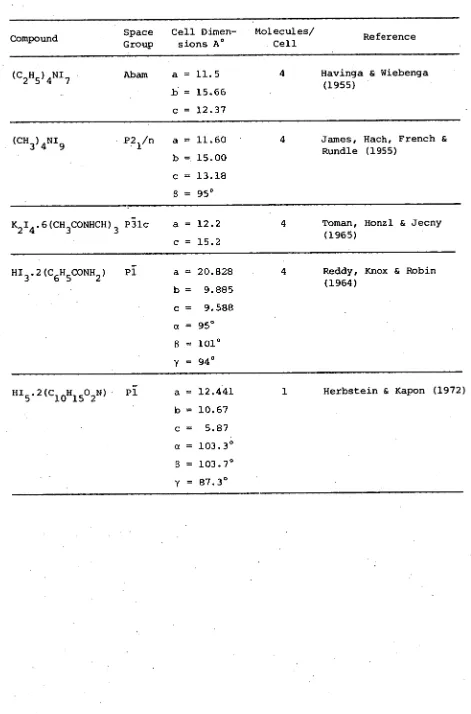
TABLE 1-4
Structural Data for Polyiodides
Compound Space Cell Dimen- Molecules/
Group sions A ° Cell Reference CsI
3 Pnma a = 11.09 4 Bozorth & Pauling (1925) b = 6.86 Tasman & Boswijk (1955) c = 9.98 Runsink, Swen-Walstra &
Migchelsen (1972) NH I
4 3 Pnma a = 10.819 4 Mooney (1935)
b = 6.640 Cheesman & Finney (1970) c= 9.662
-(I) Cmca a = 14.207 Migchelsen & Vos (1967) b = 15.220
c = 14.061 (C
2H5)4NI3- (II) Pnma a = 14.522 Migchelsen & Vos (1967) b = 13.893
c = 15.156 (C
6H5)4AsI3 P2/n a = 15.34 2 Mooney-Slater (1958) b = 7.63 Runsink, Swen-Walstra &
Migchelsen (1972) c = 10.63
a
=
93•4 °FeI
3 R5m a = 8.522 c = 17.05
Bernstein & Herbstein (1968)
CsI4 P2
1 /a a = 11.19 4 Havinga, Boswijk & b = 9.00 Wiebenga (1954) c = 10.23
=l14°
(CH 3 ) 4 N1 5 C2/c a = 13.34 4 Hach & Rundle (1951) = 13.59 Brockema, Havinga &
Wiebenga (1957) c = 8.90
TABLE 1-4 cont.
Compound Space Group
Cell Dimen- sions A °
Molecules/
Cell Reference
(CH)NI Abam a.= 11.5 4 Havinga & Wiebenga
2547 (1955)
b = 15.66 c = 12.37
(CH 3 ) 4 N1
9 P2/n 1 a = 11.60 4 James, Hach, French & Rundle (1955)
b = 15.00 C = 13.18 6 = 950
KI.6(CHCONHCH) P51c a = 12.2 4 Toman, Honzl & Jecny
243 3
(1965) c = 15.2
HI
3.2(C6H5CONH2) PI a = 20.828 4 Reddy, Knox & Robin
b = 9.885 (1964)
c= 9.588
= 101 °
y = 94 °
HI
5.2(C10H1502N) Pi a = 12.441 1 Herbstein & Kapon (1972) b = 10.67
c= 5.87 a = 103.3 °
3
Preliminary investigation by R.M. Bozorth & L. Pauling (1925) Structural determination by H.A. Tasman & K.H. Boswijk (1955) Refinement by J. Runsink
et
atii
(1972)This compound crystallizes in space group
Pnma
with cell dimensionsa
o
=
11.09,b
o
=
6.86, Co = 9.98 A°. Individual tri-iodide ions can bediscerned lying in layers which also contain the caesium cation. These 1 3
layers are at right angles to the
b-axis
and cut it at y=17 and y=4. The tri-iodide group is asymmetric with interbond distances of 2.82 and 3.10 A°; the interbond angle is 176°. The average non-bonded inter-iodine distance is 4.34 A°.1 - 4 - 2 Ammonium tri-iodide, NH
4I-3.
Initial determination by R.C.L. Mooney (1935) Refinement by the author (1969) (see Chapter 4)
This.compound is isomorphous and isostructural with CsI 3, but has
a slightly smallercell:
ao
=
10.819, 60 = 6.640, Co = 9.662 A°. Theasymmetric tri-iodide group has interiodine distances of 2.791 and 3.113 A°. The anion is linear to within 0.1°, and there is one tri- iodide. - nitrogen distance significantly shorter than the others, which may be evidence for a form of hydrogen bonding with the possibility of
rotation or torsion of the ammonium group about the N-H...I axis.
1 - 4 - 3 Tetraethylammonium tri-iodide, (C 2 H ) NI3
Structural determination by T. Migchelsen and A. Vos (1967)
I belongs to space group CmCa with cell dimensions
ao
=
14.207,b
o = 15.220 and Co = 14.061 A ° ; and modification II belongs to Prima. with dimensions a
o = 14.522, bo = 13.893 and co = 15.156 A ° . Both forms have two crystallographically independent tri-iodide groups and in both cases these are situated on mirror planes. The arrangement of the tri-iodide anions within these planes or layers in both compounds is similar, but the stacking of the layers is different. In modifica- tion II the layers are almost exactly superimposed, but in I the
successive layers suffer a shift of half a cell translation in the
y
direction. In both modifications the cations lie in holes formed by the eight I -3 groups.In modification I the special position occupied by the tri-iodide ion has 2/m symmetry and the ion is thus linear and symmetric. The interiodine distance in the two independent 1 3 groups is 2.928 and 2.943 A ° respectively, but the authors do not regard the difference in length to be significant. In the case of modification II the two independent tri-iodide ions are asymmetric and non-linear with inter-iodine distances of 2.912, 2.961 A ° and 2.892, 2.981 A ° , and interbond angles of 177.7 ° and 179.5 ° respectively. In this case the dimensional differences are judged to be significant.
1 - 4 - 4 Tetraphenylarsonium tri-iodide, (C H ) AsI Structural determination by R.C.L. Mooney-Slater (1958) Refinement by Runsink
et
atii
(1972)This compound crystallizes in the monoclinic space group
P2/n
with two molecules in the cell of dimensionsa
o
=
15.34, bo = 7.63, Canion contacts across the unpopulated space between the layers than within these layers, which probably accounts for the pronounced
cleavage exhibited by the crystals of this compound. The tri-iodide units are well separated with an average interionic distance of 5.79 A ° . The tri-iodide anion is symmetric with an interiodine distance of
2.90 A ° , but is bent with an interbond angle of 176 ° . The average carbon-iodine distance agrees well with that observed in tetraphenyl-arsonium iodide.
1 - 4 - 5 Ferricinium tri-iodide, (C 5 H 5 ) 2 FeI 3
Structural determination by T. Bernstein & F.H. Herbstein (1968)
This interesting compound crystallizes in the rhombohedral space group
R3M,
with cell dimensions (referred to hexagonal axes) ofa
o
=
8.522, Co = 17.05 A ° . In the cell, each tri-iodide anion is surrounded by a rhombohedral cage of eight ferricinium cations. The anion is assumed to be linear and symmetric, with an interiodine distance of 2.93 A ° , but there is some indication from the thermal parameters of the iodine atoms that the structure could well be built up from a disordered arrangement of slightly bent asymmetric tri-iodide ions. There is clear evidence that the cyclopentadiene rings are rotationally disordered, but it is not possible on the X-ray evidence to distinguish between intramolecular 'free' rotation of the rings or a disordered arrangement of rigid ions.
1 - 4 - 6 Caesium tetraiodide, CsI
Structural Determination by E.E. Havinga
et atii
(1954)This compound crystallizes in the monoclinic space group Pya with four molecules of CsI
4 in the cell which has dimensions
a.
11.19,b
2-
loose assemblage of 1 3 ions and iodine molecules to form 1 8 ; this 2-
[image:28.554.47.497.55.569.2]requires the compound to be formulated as Cs 2 I 8 . The 1 8 group is very nearly planar and roughly Z-shaped; the important interiodine distances and bond angles are shown in Figure 1 - 3. From this figure it can be seen that the tri-iodide units are asymmetric and bent, and that the I - I distance in the iodine molecule does not differ greatly from the value of 2.70 A ° observed for solid iodine
(Townes and Dailey [1952]). The shortest interionic distance is
3.9 A ° and the minimum cation-anion distance agrees with the sum of the ionic radii of Cs+ and I.
1 - 4 - 7 Tetramethylammonium pentaiodide, (01 3 ) 4 NI 5
Structural determination by R.J. Hach & R.E. Rundle (1951) Refined by B.J. Broekema
et atii
(1957)Tetramethylammonium pentaiodide crystallizes in the monoclinic system, space group
C2/c,
with unit cell dimensionsao
=
13.34,b
o
= 13.59, Co = 8.90 A ° , o = 107 ° . The iodine atoms form planar V-shaped I i5 ons arranged in almost square nets. These nets are approximately parallel to 001 and are separated by 4.3 A ° . The cation nitrogen lies in the same plane as the net at the intersection of the net diagonals. The I
5 group is planar to within 0.2 A ° and the arms of the V are linear to within 4 ° ; the angle between the arms is 95 ° . The two independent interiodine distances within the ionic group are 2.81 and 3.17 A ° . The shortest non-bonded interiodine distance is 3.55 A ° .
1 - 4 - 8 Tetraethylammonium hepta-iodide, (C
2H5)4NI7
Structural determination by E.E. Havinga & E.H. Wiebenga (1955).
Figure 1 - 3, Interiodine distances and angles.for 2-
the I
cell of dimensions a
o = 11.5, bo = 15.66, co = 12.37 A°. The -
structure consists of 1
3 ions and iodine molecules, with the tetra- • ethylammonium cation occupying holes in the structure. The authors
consider that as the shortest distance between the iodine molecules and the tri-iodide groups is 3.47 A°, there is no evidence for the existence of the I; group in this compound and that it consequently should be described by the formula (C
2H5)4NI3.2I2. The interiodine distance in the iodine molecules is 2.76 A°; whichever space group is the correct one, the tri-iodide unit must be symmetric with an inter- iodine distance of 2.91 A°. Space group Abam imposes the constraint that the tri-iodide group must be linear.
1 - 4 - 9 Tetramethylammonium ennea-iodide, (CH 3 ) 4 N1 9 Structural.determination by W.J. James et
aai
(1955)This polyiodide crystallizes in the monoclinic system, space group
P2 1 /n.
Four molecules are accommodated in the cell of dimensionsa
o = 11.60, bo = 15.0, Co = 13.18 A° ,
s o =
950•
The arrangement of iodine atoms in the structure is reminiscent of that in (CH 3 ) 4 NI 5 , in that five-ninths of the iodine atoms occur in layers, within which they
- are grouped into V-shaped 1
5 units. These sheets are separated by a distance of 9..1 A° and between these sheets are found the tetramethyl-ammonium cation and the six iodine molecules which surround the cation with their molecular axes perpendicular to the layers of 1
5 units. The interiodine distance in the molecular groups between the layers is 2.67 A° , and the separation between the molecular group and the iodine atoms at one end of the arm of the V-shaped 1
5 group is either 3.24 or 3.43 A°. The I-
Figure 1 - 4, The 1 5 group of (CH
Figure).
1 - 4 - 10 Dipotassium tetra-iodide hexa-(N-methylacetamide),, K I
2-4---3 .6(CH CONHCH3) -
Structural determination by K. Toman
et
atii
(1964).The crystals of this solvated polyiodide are trigonal, space group P31c with a unit cell (referred to hexagonal axes) with dimensions
a
o
=
12.2, Cb = 15.2 A ° . The cell contains two stoichiometric units with 13 ions and I ions alternating in arrays parallel to the C-axis. The planar N-methylacetamide molecules are so arranged that each iodide ion is in the centre of a trigonal cage of six -NH groups, and each potassium cation is similarly caged by six carbonyl oxygens. There is evidence that the tri-iodide ion is avoided by the -NH groups as the iodide ion to nitrogen separation is 3.74 A ° , while the distance between the nitrogen and the terminal iodine of the tri-iodide group is 4.01 A ° . The symmetry of the space group requires the tri-iodide anion to be both symmetric and linear. However, as in the case of ferricinium and tri- iodide, an examination of the thermal parameters of the I -3 iodines indicates that the structure may be partially disordered. The authors consider that a bent and possibly asymmetric tri-iodide ion may statis-tically satisfy the symmetry requirements of the space group by random rotation about the trigonal axis or by end-for-end orientation disorder, or both. The interiodine distance, assuming a linear and symmetric unit, is 2.945 A ° ; the distance between 1
3 and I - ions in the axial direction is 4.64 A ° .
1 - 4 - 11 Hydrogen tri-iodide di7(benzamide), HI
3.2(C6H5CONH2) Structural determination by T.M. Reddy
et atii
(1964)cell a
o = 20.828, bo = 9.885, co = 9.588 A° , ao = 95° , 0o = 101
0,
y
o = 94°. The structure consists of arrays of dimerized benzamide molecules which form long channels in which the tri-iodide ions are . aligned as two parallel chains 4.6 A° apart. The two crystallo- graphically distinct tri-iodide ions in the unit cell are both bent, with a bond angle of 177°, and are both slightly asymmetric. Bond lengths in both cases are 2.921 and 2.943 A°. . The distance between neighbouring tri-iodide ions in the chains is 3.8 A °, suggesting at least a partial polymerization of these groups, a suggestion which may be supported by the fact that the chains are linear to within 16 ° .
The position of the hydrogen cation was not determined in this analysis, and the possibility that the cationic group may in fact be H 30 does not seem to have been explored - such an hypothesis has the merit of providing this compound with a cation of reasonable size and does not do violence to the available analytic data for this compound.
1 - 4 - 12 Hydrogen penta-iodide di-(phenacetin) HI .2(C H 0 N) 5----10 13-2-- Structural determination by F.H. Herbstein & M. Kapon (1972)
As is the case with the previously described solvated hydrogen polyiodide, this compound crystallizes in the triclinic system, space • group P7 with one molecule in the cell with dimensions ao = 12.441,
b = 10.67, C
o = 5.87 A°, ao = 103.3° , 00 = 103.7°, yo = 87.3°.
The structure is composed of parallel sheets of organic molecules and • polyiodide ions. The latter contain zigzag chains of alternate
iodine molecules and symmetric 1
3 ions. The bond length of the
tri-iodide ion is 2.907 A°, and that of the iodine molecule is 2.748 A°. The distance between the terminal atoms of the tri-iodide ion and the iodine molecule is 3.550 A°, commensurate with the spacing (3.50 A°) found in crystalline iodine.
iodide sheet. The acidic protons are assumed to be associated with the neutral organic molecules, linking neighbours by symmetrical hydrogen bonds between symmetry related carbonyl groups. This . interpretation is supported by the carbonyl oxygen-carbonyl oxygen
separation across the symmetry centre of 2.44 A°, which is less than the van der Waal's diameter of oxygen (2.80 A°).
In the absence of analytic data, it is not possible to determine whether the assignment of the acidic protons to the phenacatin molecules
is the correct interpretation, or rather that, as in the case of HI
3.2(CH5CONH2), the compound contains the H30
+
cation. In either case the possibility cannot be rejected on the basis of the published informa-tion; the implications of this hypothesis are discussed further in Chapter 7, Section 7 - 5.
- 5 Polyiodide Bonding in Relation to Stability and Structure
From this body of structural data the following generalizations can be made concerning polyiodide anions in the solid state. First, the anions are catenated assemblages of iodine atoms which are either linear - as in the case of the tri-iodide ion - or involve bond angles
2- close to ninety degrees - as in the case of the I i
8 on. Second, the bond distances are always some 5 to 15% greater than twice the covalent radius of iodine (1.33 A°) (Cotton and Wilkinson [1973]). Third, together with the iodine molecule, both the I-3 and the I- ions act to
5
some extent as 'building blocks' out of which the more complex anions are assembled. Fourth, a common feature of the structures so far determined is the disposition of the polyiodide anions in layers or rows within the unit cell. This, and the mutual orientation of the
- tri-iodide ion in the structures containing the 1
3 entity, is reminis- cent of the structure of solid iodine (Townes and Dailey [1952]).
static point of view have been made (van Arkel and de Boer [1928], Havinga [1957]), but they fail to explain satisfactorily the observed anion geometries. • _ The 1
3 ion bonding was discussed from the stand- point of molecular orbital theory by Pauling [1940], and a molecular orbital model for this anion involving 5d and 6s orbitals was advanced by Kimball [1940]. This model was criticised by Pimentel [1951]; he pointed out that the energy required to promote an electron from a halogen d-orbital is considerable, and that this is compensated by the energy of hybridization is an assumption of questionable validity. His alternative model, also proposed independently by Hach and Rundle [1951], treats the bonding as arising from the delocalization of the valency p-electrons to form a simple sigma bond between halogen centres.
This pa-bonding model was later extended in a simple one-electron LCAO-MO form by Havinga and Wiebenga [1959] to all polyhalides and interhalogens. Their treatment satisfactorily predicts all observed bond-angles and configurations with the exception of the interhalogen compound IF
7. Subsequent more elaborate SCF-MO calculations have been carried out on a number of polyhalogen species and all demonstrate the adequacy, of this model to account for the observed properties of these compounds subject to the limitations of such treatments when applied to atomic systems involving a large number of electrons. In view of the very large number of electrons involved in the polyiodide cases, the results of such treatments are remarkably good.
In 1959 Mooney-Slater observed that, regardless of the nature of the bonding of the tri-iodide ion, the configuration of the 1
3 species was sensitive to its crystallographic environment, the anion being long and markedly asymmetric in the relatively unstable ammonium tri-iodide and short and symmetric in the more stable tetraphenylarsonium tri-iodide. With the crystallographic data available at that time (which included those structures already described in which I
- - iated with iodine molecules to form 1 2 , I
7 , etc.) she showed that • 8
there appeared to be a systematic relationship between the overall length of the I; anion and the degree of asymmetry in the bond lengths. This systematic relationship was compared to the behaviour of the H
3 molecule-ion system by Slater [1959], who attributed the dependence of configuration of the anion upon its surroundings to 'environmental
- pressure', ascribing the symmetry of 1
3 in (C6H5)4As13 to the crowding of the anion by the bulky tetraphenylarsonium cation.
This interpretation was later challenged by Rundle [1961] who related the observed configurations of the 1 3 ion to the balance struck in parti-cular crystalline environments between the tendency of coulombic inter-actions between the cation and the anion to favour an asymmetric form and the opposing tendency of bonding interactions to favour a symmetric
arrangement of iodine atoms. Rundle observed that the trend towards greater stability and more symmetric anion geometry which accompanies an increase in cation size runs in the expected direction, as the coulombic
influence would decrease as the cationic radius increased.
This latter interpretation can be accommodated within the framework of the p-sigma model of polyiodide bonding. The valency electrons of
iodine are well screened from the nuclear charge by the large number of electrons in orbitals of lower principal quantum number. Consequently, when a polyiodide anion is formed, the valency p-electrons readily
delocalize, creating a weakly sigma-bonded entity. The other conse- quence of the screening effect is the ease with which external fields can distort or polarize the valency electron distribution over the anion. Any such distortion is accompanied by a change in the equilibrium config-uration, and as this change is expressed as a lengthening of one or other of the I - I bonds, it is accompanied by a decrease in the stability of • the complex. Thus in a crystalline environment a polyiodide anion can
severe electrostatic disruption. This effect has been examined in some detail by Brown and Nunn [1966] who, by a series of SCF-MO one electron calculations, showed that the free tri-iodide ion should be linear and symmetric, but that in the CsI 3 lattice the crystal field distorts the electron distribution so that the anion configuration of minimum energy is an asymmetric one with calculated bond lengths close to those determined for the CsI
3 structure.
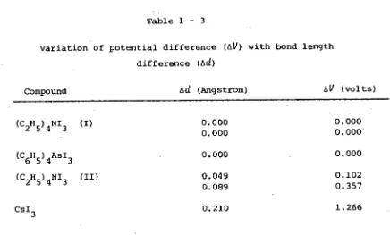
The inference that the asymmetry of the tri-iodide ion in a given structure reflects the asymmetry of the electrostatic environment rather than the size of the cation has been elegantly substantiated by the study made by Migchelsen and Vos [1967] of the two modifications of
(C
2H5)4NI3 (see Section 1 - 4 - 3). In the case of the two crystallo- graphic modifications of this compound the effects of change in cation size cannot arise; however, modification I of this compound exhibits two independent and symmetric tri-iodide ions which differ in total length, in contrast to modification II which possesses two independent asymmetric anions with the same total length. Migchelsen and Vos also carried out calculations similar to those performed by Brown and Nunn; these showed that in the case of modification I there was no potential difference due to external charges between the terminal iodines of the symmetric anions. However, in modification II potential differences of the order of 0.1 - 0.35 volt existed between the terminal iodines of the two asymmetric anions present in this form of (C 2 H 5 ) 4 NI 3 . The variation of AV, the potential difference relative to the central iodine, with Ad, the difference in bond length, for a number of structures
Table 1 - 3
Variation of potential difference (AV) with bond length difference (Ad)
Compound Ad (Angstrom) AV (volts)
(C
2H5)4NI3 (I)
(C
6H5)4AsI3 (C
2H5)4NI3 (II)
0.000 0.000 0.000
0.049 0.089
0.000 0.000 0.000
0.102 0.357 CsI
3 0.210 1.266
These data indicate that there is a systematic relationship between the asymmetry of the electric field experienced by the tri-iodide ion and the asymmetry of the equilibrium configuration adopted by the ion under this field.
1 - 6 The Aim of this Work
The stability of solid unsolvated tri-iodides would appear, from the evidence assembled above, to be a function of the asymmetry of the electrostatic environment experienced by the anion in the crystalline lattice. Insofar as this asymmetry is determined by the size of the cation, the stability trend of the unsolvated tri-iodides of singly charged cations can be understood. It is also reasonable to expect the same principle to govern the stability of the more complex poly- iodide anions (I
CsI
3
e
1•25
1•0
Av
0.7
0.5
Et
4
NI
3
-46
0.25-
Et NI3-1I
‘113
cih
r4
4
AsI3,Et4NI3-I
03 •10 -20
Ad
(Angstrom)
The major objective of this-work was to examine this hypothesis critically in the light of the known deficiencies of simple crystal field theory as applied in the field of transition metal chemistry, and to test it by comparing the structure of a solvated alkali tri-iodide with that of the unsolvated tri-tri-iodides. The solvated tri- iodide chosen for this comparative study was the potassium compound, KI
3.H20. This choice was made for a number of reasons: perhaps the most important being that KI 3 .H 20 is the most stable of the hydrated ,polyiodides. Further, this compound is presumed to be a tri-iodide
on the basis of both analytic data and phase studies; in this
respect it stands in sharp contrast to the hydrated sodium and lithium tri-iodides. The presence of tri-iodide anions within the structure would simplify the comparison of this crystalline environment with that of the unsolvated tri-iodides which are already known to contain discrete 1 3 units. Also, the solvate molecule is water, and there is in existence a considerable body of information concerning the roles performed by water molecules in other crystalline compounds which could be drawn on for comparison.
The solution of the structure of KI
3.H20 occupies a central place in this study, but in addition an attempt has been made to extend the number of accurately known unsolvated tri-iodide structures by the refinement of the structure of NI-I
43 and the solution of the structure of RbI
3' Further, it was hoped that as a result of this examination a simple model which would represent the response of the 1
3 ion to its crystallographic environment could be developed, and that in the light Of this model a better understanding of the systematic structural chemistry of both the solvated and unsolvated tri-iodides could be gained.
Chapter 2 - The Theoretical Basis of X-Ray Structural Analysis
page
2 - 1 Diffraction of X-rays by Crystals 33
2 - 2 X-ray Scattering by Atoms 35
2 - 3 The Structure Factor 36
2 - 4 The Electron Density Distribution 38
2 - 5 The Phase Problem 39
2 - 6 The Patterson Method 41
2 - 1 Diffraction of X-rays by Crystals
The theory of the interaction of X-radiation with matter in the crystalline state has been exhaustively reviewed elsewhere (James
[1948]); for this reason the discussion given here concentrates on the application of X-ray diffraction to the determination of crystal struc-tures.
In 1912 von Laue suggested that if in fact X-radiation possessed wave-like properties, then the interatomic spacing of crystalline substances should be of the right order of magnitude for a crystal to act as a diffraction grating for X-rays. The first observation of X-ray diffraction was made in the same year by Friedrich and Knipping when they irradiated a single crystal of copper sulphate pentahydrate with an X-ray beam. This observation gave the first clear proof of the wave character of X-rays, and von Laue showed that the results of the diffraction experiment could be described in terms of diffraction from a three-dimensional diffraction grating (Laue, Friedrich and
Knipping (1912]). As a result of these experiments W.L. Bragg developed a treatment of X-ray diffraction in terms of reflection of the incident X-ray beam by the lattice planes of the crystal (Bragg [1912]) and he derived the simple reflection law
2d cos 0 (0 = 90 - 0)
which now bears his name, and where d is the interplanar spacing, 0 the angle of incidence, A the X-ray wavelength and
n
an integer specifying the order of reflection.derivation is, however, valid as it can be shown that scattering from electron density which does not occupy a rational lattice plane may be treated to yield a resultant as if the scattering took place in that plane. The nature of the electron density distribution in the unit cell volume controls the magnitude of these resultants, and gives rise to the differing intensities of reflection observed for different lattice planes.
If Bragg's Law is recast in the form
sin 0
= nA/2d
it can be seen that sin 0 is proportional to the reciprocal of the inter-planar spacing,
d.
This was the point of departure for the development by Ewald [1921] of the concept of theAecipucat tattice.
This concept was further developed and applied by Bernal [1926] to the problem ofinterpreting X-ray diffraction patterns, and now provides one of the most convenient tools available for the study of the diffraction of X-rays by crystals. The most significant property which adapts it to this purpose is that in the reciprocal lattice distances are measured in reciprocal units,
d*
(=1/d), these quantities having the advantage of being directly proportional to sin 6. Thussin 6 =
A
d*
The reciprocal lattice, which may be considered to exist in a cont-inuum
(tecipucat
oace)
defined by its coordinate system, is described by the edgesa*, b*, c*
and interaxial angles a *,a*,
y * of the reciprocal cell. These bear the same relationship to the reciprocal lattice as do the unit cell elements db, c,
a,a,
y to the lattice of the real crystal. Conventionally, reciprocal quantities are designated by starred symbols to distinguish them from the analogous real ordinect
quantities. Therelationship between the direct and reciprocal cell elements can be compactly expressed in vector notation for the general (triclinic) case
a* = (b) x (c)/(a.b x c)
b* = (c)
x (a)/(a.b x c)c * = (a) x (b)/(a.b x c)
As the reciprocal space metric is directly proportional to sin 0,
the direction of a reflection from the crystal plane with Miller indices
hkt
can be vectorially specified by the reciprocal lattice pointh
reciprocal cell units in the a * -axial direction,
k
units in the b * -axialdirection and t units in the e-direction. Thus all reflections from
the crystal planes can be associated with their corresponding reciprocal
lattice points, and further, the reciprocal lattice possesses the entire
symmetry of the direct lattice to which it is related; these two
proper-ties make possible the convenient discussion and treatment of reflection
data in reciprocal lattice notation.
2 - 2 X-ray scattering by Atoms
It was implicit in the discussion in Section 2 - 1 that X-rays are
scattered by the extranuclear electrons of the atoms which make up the
crystal. For convenience, in describing the scattering behaviour of
crystals, the unit of amplitude is taken to be the amplitude of the X-ray
wavelet scattered by a single electron.. On this basis, for a 'reflection'
from a given lattice plane, the amplitude of the wave scattered by a single
cell of the crystal (the
6tAuctuke iactwo
will be the sum of theapprop-riately phased amplitudes of the wavelets scattered by each electron in the
cell. This form of the structure factor is not very useful in view of the
large number of electrons usually involved and the limitations which exist
regarding a precise knowledge of their position, even when the details of
the structure are known. A more useful approach is to make use of the
knowledge gained from atomic structure theory (Hartree [1927], [19571)
associated with each atom, and to group together the components of the structure factor so that each group is associated with one atom in the cell.
Using this approach, a detailed knowledge of electron position is not necessary. All that is required is a good description of the aver-age spatial distribution of the electron cloud with respect to the atomic centre. Each group of terms in the structure factor then re-presents the appropriately phased contribution made by the electrons of each atom to the amplitude of the wave scattered by the cell. The scattering power of an atom, usually designated
6,
is measured in the same units as the structure factor, namely, the scattering power of a single electron. The maximum value that can therefore be attained by 6 for a given atom is equal to the atomic number Z. If the scattering electrons were concentrated at the atomic core - a 'point atom' - there would be no variation of 6 with scattering angle (normally expressed in terms of (sin 6)/X). However, as atoms have an extended electronic structure,6
decreases from an initial value of Z with increasing(sin 6)/X, due to the destructive interference of the wave fronts scattered by each electron in the electron cloud. The detailed behav-iour of
6
as a function of (sin 6)/X, derived from atomic structure calculations, is available in the literature (Thomas and Umedu [1957], Henry and Lonsdale [1965]) for most elements in a number of valency states.2 - 3 The structure factor
where
6.
is the scattering power at (sin )/X of the jth atom in the cell, and (1)j is the phase of the structure factor. This can also be written as the explicit function
F
hkt
=
E 6. c
iln(hx
j
+
ky. + tz.)
j
J
where X.,
y.,
z. are the fractional coordinates of the jth atom. SomeJ J J
computational convenience is gained by expressing the structure factor as the sum of real and imaginary components:
F
hta
=
E6. cos (1). +
E6.
sin 4).Again, this can be written as an explicit function of the fractional coordinates:
F
=
E6. cos
27(hx. ky. +
£z)
hkt.
.
J 1 1
1
+ E & sin 2ff(hX. +
lay. +
j
J
J
In those cases where the crystal possesses a centre of symmetry, that is, every atom at
x,y,z
is accompanied by another in the cell at-x,-y,-z,
the expression for the structure factor may be simplified toF
h
=
2 E6
J
• cos
2 (hx • +
lay. + £.
z1 )
1
due to the cancellation of the imaginary component from symmetry related atoms. In this centrosymmetric case, as the atoms occur in pairs
(except for an atom occupying the centre of symmetry, in which case it is its own . centrosymmetric mate and must be treated specially) the summa-tion need only be carried out over half the contents of the unit cell. In general, the presence of
symmetry elements
will simplify the general expression forfactor expression for each of the 230 space groups is contained in Volume I of the
Intermational
Tabte4 X-tay
CAystaitoguphy
(Henry and Lonsdale [1965]).2 - 4 The Electron Density Distribution
Any periodic function 6(X) of unit periodcan be written as
6(x)
= F(h)e-2Trihx
h=--
where
h
is integral andF(h)
are the coefficients of the Fourier series for the function6(X).
The electron density distribution in thecrystal is periodic in three dimensions as a consequence of the crystal being built up by the three-dimensional repetition of identical struc- tural units. A Fourier series for the electron density distribution, p(Xyz), over the unit period specified by the unit cell can be written
in a manner entirely analogous to that for the one-dimensional example given above. The Fourier coefficients in this case are the structure
factors,
F
at
,
so thatp(xyz)
=
1
T
e-27i(hx+ky+tz) .
L
k t
choice, once made, must be maintained. In this work the convention adopted by the
Intexnationat Tabte4 X-Aay
CAlotattognaphy (Henry and Lonsdale [1965]) has been followed in which the negative sign is associated with the Fourier transformation from reciprocal to direct space.By noting that the structure factor is a complex quantity which may be splitinto phase and magnitude components,
Fhkt =
Fhkel
e2ff'illhkt
the three dimensional Fourier series for the electron distribution in the unit cell can be given the alternative form where 2Tria at is the phase angle of the structure factor under consideration. The electron density expression can then be written as
1 e-Zni(hx+ky+tz)
P(xyz) = v EEEIF Lu le 2nia hke
h
k t
'
which can be simplified to
p(xyz)
=rIF Lizt ie
-2ffilhx+ky+tz-ah kt)
h k t
'
2 - 5 The Phase Problem
As shown in the previous section, an expression can be written for the electron density distribution in the unit cell in terms of the phase and magnitude of the structure factors
Fut .
The fundamental difficulty of the technique of structure solution by diffraction methods is thepha4e
pubtem,
namely, that the diffraction process using incoherentthe structure factors are known the electron density distribution in the unit cell may be computed directly. At present the phase problem must be solved before the distribution of electron density can be determined by computation.
• A solution of the phase problem will consist of a set of predicted phases - ideally, one for each observed structure factor magnitude. For
such a solution to be accepted as the correct one, the electron density distribution calculated from it must meet a number of criteria:-
(a) The electron density must be real, positive and continuous everywhere in the unit cell.
(b) It must be concentrated in approximately spherical regions (atoms).
(c) Once the atoms have been identified, the structure so revealed must be consistent with the existing body of knowledge concerning the structures of chemical compounds, with interatomic distances and angles variable only within limits established by previous experience. (Naturally the exercise of this criterion involves an element of judgement,
otherwise novel structures would never be discovered).
taken together are very restrictive, and the probability of arriving at a solution to the phase problem which conforms to all three and which generates an incorrect electron distribution is judged to be . vanishingly small.
The first stage in the solution of the phase problem is the generation of a
phasing model..
This is a model of the electron density distribution which yields phases sufficiently correct for a convergent process of model improvement to be initiated. This process will normally consist of a cyclic alternation of structure factorcalculations and Fourier syntheses, in the course of which the positions of all the atoms in the unit cell are discovered. When this stage is complete, a semi-automatic process of least-squares refinement of all atomic parameters may be commenced.
A number of techniques useful for the development of a phasing model are available to the crystallographer. These include
trial-and-error methods, the anomalous dispersion technique, the method of iso-morphous replacement, the heavy-atom and Patterson techniques, and the more recently developed 'direct' methods. Each technique has its own
strengths and weaknesses, and consequently its own area of special
utility. In the field of inorganic structure determination, the method involving the interpretation of the Patterson function is usually employed. However, the applicability of direct methods has also been investigated as a result of their successful use for the solution of organic struc-tures. In the following sections these two methods are outlined.
2 - 6 The Patterson Method
In 1935, Patterson (Patterson [1934, 1935a, 1935b]) showed that the Fourier synthesis prepared by using the squared moduli of the structure
1
observed diffraction intensities, no preliminary assumptions concerning the structure need be made. The maxima in the Patterson function
P(uvw)
correspond to vectors between all possible pairs of atoms in the crystal structure, with all vectors referred to a common origin. Thus, if atoms are located in the crystal at positionsxi , yi ,
zi and Xi, Z., the Patterson function will display a peak at ut, v4, GOA. , such thata
4 k
zi
The height of any such peak will be roughly proportional to the product of the number of electrons in the two atoms inter-related by the vector in question.
For a compound having
n
atoms in the unit cell, the Patterson syn-thesis will haven
2
peaks, each representing one of then
vectors from each of then
atoms in the cell. Asn
of these vectors are of zero length, representing the vector from each atom to itself, these are concentrated as a large peak at the origin. The remainingn
2
- n
non-zero vectors are represented by peaks distributed throughout the cell volume, with heights proportional to the product of the peak heights of the inter-related atoms.It was first shown by Langmuir and Wrinch (Langmuir and Wrinch [1938]) that in principle it is possible to recover the atomic distri-bution from the vector set represented by the Patterson function. Even though both real and hypothetical examples of different atomic distri-butions which give rise to the same vector set are known, (Pauling and Shappell [1930], Minzer [1949], Gurrido [1951], Hoseman and Bagchi
not from the possibility of homometric structure ambiguities, but rather from the overlap of peaks in Patterson space as a consequence of their finite size. The Patterson synthesis for a compound containing a moderate number of atoms will display
n
2
-n
non-origin peaks in the volume of the unit cell, and these in most cases will overlap to give some featureless regions of vector density. The severity of this problem can be reduced by modifying the coefficients of the synthesis,so that the scattering behaviour of the atoms approximates to that of point atoms. The 'sharpened' Patterson function so produced will contain approximations to point-vector peaks, with a consequent reduc-tion in overlap.
A fundamental limitation is imposed on this sharpening procedure by the fact that the set of coefficients is finite in number. A point object can only be perfectly represented by a Fourier series with an
infinite number of terms. The use of a finite data set for the computa-tion of a sharpened Patterson funccomputa-tion introduces around each peak a sequence'of secondary ripples which may, by their own overlap, nullify any improvement in resolution afforded by the sharpening procedure.
The wide range of techniques which have been devised for the inter-pretation of Patterson functions has been described elsewhere (Buerger
[1959]). A brief description of only two of these methods is given below, namely, the use of Harker sections and image-seeking methods.
Although those symmetry elements with translational components
(glides .and screws) of the crystal appear in the symmetry of the Patterson function as the corresponding non-translational• elements (mirrors and rotation axes), it was shown by Harker that the symmetry elements of the space group of the atomic distribution were reflected in linear and planar concentrations of. vector density in the Patterson function. In
compound from an analysis of the disposition of the Harker lines and planes in the Patterson function. In conjunction with a knowledge of the distribution of atoms over the equipoints in the cell, the analysis of Harker lines and sections can be useful in developing a trial structure for use as a phasing model. However, like all other Patterson techniques, its application is complicated by fortuitous overlap of vector peaks.
The image-seeking method and related superposition techniques represent a development by Buerger [1950a, 1950b, 1959] and others
(Lindquist [1952], Bezjak [1953]) of the basic ideas of Wrinch [1938, 1939a, 1939b, 1950]. An essential early stage in all these methods is the identification of Patterson peaks which correspond to a single atomic interaction, or an interaction of known magnitude. This identification is often assisted by predictions of vector lengths, made from a knowledge of bond lengths or substructure configurations derived from related structures and other chemical data. Once such an
identification has been made, the origin of a copy of the Patterson function is shifted to the peak position, and to positions related to it by the symmetry operations of the cell. Coincidences in peak
positions in the shifted functions are then sought. By repeating this process as many times as is necessary, the atomic distribution can, in principle, be recovered. In practice, the success of the technique relies on the correct identification of the initial vector, and such identification may be precluded by peak overlap.
this work provide a case in point. Also, the Patterson function provides a convenient check on the validity of a model, in that the vector set derived from the model must be in agreement with the distribution of peaks in the Patterson function (see Chapter 6, Section 6 - 6).
2 - 7 The Direct Methods
In the previous section, it was stated that the Patterson function affords a means whereby a trial structure can be derived for use as a preliminary phasing model. As the Patterson function is the Fourier transform of the intensity data, it should be possible to derive a trial structure from the intensity data directly. Many attempts
(Bannerjee [1933], Hughes [1949]) have been made to devise methods of an algebraic or statistical nature for the direct solution of crystal structures using only the intensity data, the unit cell dimensions and symmetry, and the chemical composition of the crystalline species.
Some of these attempts have concentrated on direct solutions in crystal space for the atomic positional co-ordinates, but the most successful attempts have involved reciprocal space solutions for the phases of the structure factors. This is a rapidly developing area in the field of structure determination by diffraction methods, and so far the most
progress has been made in the solution of organic structures. Currently, such structures involving as many as 100 atomic parameters have been solved in both centrosymmetric.and noncentrosymmetric space groups by the routine application of direct methods of solution.
methods includes other physically reasonable assumptions which limit the distribution of the magnitudes and phases of the structure factors. These commonly include the assumptions that the electron density
distributions can be successfully approximated by the superposition of spherically symmetric atomic electron distributions, that these atomic distributions are identical, and that they are randomly distributed in the volume of the unit cell. As a first approximation, it appears that the applicability of the direct methods to a given structural problem depends upon the degree to which the structure departs from these assumptions.
Historically, the first practical application of direct methods was that of Harker and Kasper in 1948 in their work on the structure of decaborane (Harker and Kasper [1948]). Their approach involved the use of inequality relations which allowed the signs of a sufficient number of the structure factors to be determined for the structure to be solved.
Another approach was developed by Sayre [1952], who showed that the structure factors for a structure containing equally resolved atoms could be related by equations of the form
F(h) = (0(h)[E (h') (h-h91/V hl
where F(h) is the structure factor with diffraction order specified by the vector
h, cp(h)
is a function of s, the length of the vectorh
in reciprocal space. The same relationship was also derived at the same time by Zachariesen [1952] and Cochran [1952]. Using this relationship in conjunction with the approach of Harker and Kasper [1948] it may be shown for structure factors of large magnitude thatsign(h)sign(h9sign(h+h9 = +1