OPTIMIZING THE 3D MILLING MACHINE PARAMETER TO IMPROVE THE CUTTING ACCURACY
NUR ADILAH BINTI SAWARI
OPTIMIZING THE 3D MILLING MACHINE PARAMETER TO IMPROVE THE CUTTING ACCURACY
NUR ADILAH BINTI SAWARI
This report is submitted
in fulfilment of the requirement for degree of
Bachelor of Mechanical Engineering (Design and Innovation)
Faculty of Mechanical Engineering
UNIVERSITI TEKNIKAL MALAYSIA MELAKA
ii DECLARATION
I declare that this project report entitle “Optimizing the 3D milling machine parameter to improve the cutting accuracy” is the result of my own work except as cited in the references.
Signature :………..………
Name :.……….……….…...
iii APPROVAL
I hereby declare that I have read this project report and in my opinion this report is sufficient in term of scope and quality for the award of the degree of Bachelor of Mechanical Engineering (Design and Innovation).
Signature :………..……
Name of Supervisor :……….………….……
iv DEDICATION
v ABSTRACT
vi ABSTRAK
vii
ACKNOWLEDGEMENT
I would like to express my deepest appreciation to all those who provided me the possibility to complete this report. A special gratitude I give to my final year project supervisor, Dr Faiz Redza bin Ramli and my second examiner, Ir Dr Mohd Rizal bin Alkahari who assisted and guided me with suggestions, encouragements and consultations in conducting this final year project especially in writing this final year project report. Furthermore, I would like to acknowledge with much appreciation the crucial role of post graduated students in Innovation Laboratory, who give the permission to use the requirement equipment and necessary materials to complete my experimentation on the 3D NXT milling machine.
A special thanks to my family who help me in fabricating and assembling parts and gave a lot of suggestion regarding to this project where I found it is difficult for me to solve. A special thanks also to my classmate and teammate who help me on giving some suggestion and encourage me in completing this final year project.
Last but not least, I would like to express my gratitude to any individual or group whom I have not mention that has gave me support and advices in order to complete this project especially to Design and Innovation’s students and lecturers.
viii
TABLE OF CONTENT
CHAPTER CONTENT PAGE
DECLARATION ii
APPROVAL iii
DEDICATION iv
ABSTRACT v
ABSTRAK vi
ACKNOWLEDGEMENT vii
TABLE OF CONTENT viii
LIST OF TABLES x
LIST OF FIGURES xi
LIST OF ABBREVIATIONS xiii
LIST OF SYMBOLS xiv
CHAPTER 1 INTRODUCTION
1.1 Background 1
1.2 Problem Statement 4
1.3 Objectives 4
1.4 Scope 5
CHAPTER 2 LITERATURE REVIEW
2.1 Machine tools for removal process 6
2.2 The milling machine structure 7
2.2.1 Types of milling machine 7
2.3 Milling cutter 9
2.4 Sources of error in machine tools 10
2.4.1 Machine tool error 10
ix
2.5 Lego Mindstorms NXT programming environment 11
2.5.1 NXT servo motor 13
2.6 MATLAB/Simulink toolbox 14
2.7 Method for optimization 15
CHAPTER 3 METHODOLOGY
3.1 Introduction 18
3.2 Operation of existing 3D milling machine using Lego Mindstorms NXT
20
3.3 Movement of 3D milling machine using Simulink 24 3.4 Machine parameters that influence cutting tool
movement
25
3.4.1 Equation for milling machine 26 3.5 Method to optimize 3D milling machine 27
3.5.1 Response surface 28
CHAPTER 4 RESULT AND DISCUSSION
4.1 Introduction 30
4.2 Simulink support package for Lego Mindstorms NXT hardware block
30
4.2.1 Designing the model for servo motor movement
32
4.2.2 Run model to the NXT I-Brick 35
4.3 Experimental set up 36
4.4 Experimental data for milling machine 38 4.5 Optimization the response using Minitab 42 4.5.1 Result for the response surface 43 4.5.2 Result for the response optimiser 47
4.6 Testing on 3D Milling Machine 52
CHAPTER 5 CONCLUSION AND RECOMMENDATION
5.1 Conclusion 53
5.2 Recommendation 54
x LIST OF TABLES
TABLE TITLE PAGE
2.1 Basic orthogonal array 17
3.1 Common function that been used in Lego Mindstorms NXT’s software 22 3.2 Experimental layout using an orthogonal array 28
4.1 Function for Lego Simulink Library 31
4.2 Common block that been used in this study 32
4.3 Experimental value for each parameter 37
xi LIST OF FIGURES
FIGURE TITLE PAGE
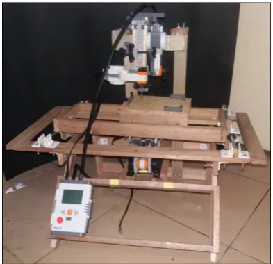
1.1 3D NXT milling machine in UTeM 1
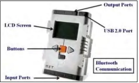
1.2 NXT Intelligent Brick (I-Brick) 2
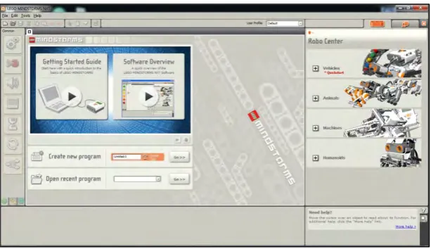
1.3 Lego Mindstorms NXT’s software 3
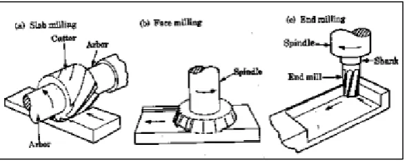
2.1 Type of milling operation 8
2.2 Machining process at different milling mode 9
2.3 Several types of end milling cutter 10
2.4 Standard education kit for Lego Mindstorms NXT hardware
(five sensors; light, sound, ultrasonic, two touch sensors), three servo motors and programmable NXT Brick
12
2.5 Lego Mindstorms NXT platform architecture 12
2.6 Internal view of NXT servo motor 13
3.1 Flow chart for this project 19
3.2 Ports to plug the output and input wire 20
3.3 Program of Lego Mindstorms NXT software 21
3.4 Simulink on NXT 25
3.5 Cutting tool movement 26
4.1 Simulink Library Browser 32
4.2 Model for rotating servo motor 33
4.3 Model for rotating servo motor by rotating another servo motor 33 4.4 Value of Port B motor displayed at the NXT I-Brick 34
4.5 Lego NXT setting before deploy to hardware 34
4.6 Result of the cutting foam 35
4.7 Servo motor in the y-axis of the machine 36
4.8 Platform of z-axis to rotate and move 37
xii
4.10 Working environment of the MINITAB 16 42
4.11 Surface plot of motor voltage vs speed vs diameter error for diameter of 3 mm
44
4.12 Surface plot of motor voltage vs speed vs length error for diameter of 3 mm
44
4.13 Surface plot of motor voltage vs speed vs diameter error for diameter of 4 mm
45
4.14 Surface plot of motor voltage vs speed vs length error for diameter of 4 mm
45
4.15 Surface plot of motor voltage vs speed vs diameter error for diameter of 5 mm
46
4.16 Surface plot of motor voltage vs speed vs length error for diameter of 5 mm
46
4.17 Response optimiser for optimal speed and motor voltage for zero percentage of diameter (3 mm)
47
4.18 Response optimiser for optimal speed and motor voltage for zero percentage of length (3 mm)
48
4.19 Response optimiser for optimal speed and motor voltage for zero percentage of diameter (4 mm)
48
4.20 Response optimiser for optimal speed and motor voltage for zero percentage of length (4 mm)
49
4.21 Response optimiser for optimal speed and motor voltage for zero percentage of diameter (5 mm)
49
4.22 Response optimiser for optimal speed and motor voltage for zero percentage of length (5 mm)
50
xiii
LIST OF ABBREVIATIONS
3D Three Dimensional
BMCD Bachelor in Mechanical Engineering (Design & Innovation) DOE Design of experiment
I-Brick Intelligent Brick MATLAB Matrix Laboratory
PID Proportional Integral Derivative USB Universal Serial Bus
xiv LIST OF SYMBOL
L Number of level
P Number of parameter Pi (3.14)
n Number of experiment/observation
Overall means response
Main effects for each factors Quadratic effect for the ith factors
V Cutting speed
S Spindle speed
F feed
f Feed per tooth
N Number of rotation
1 CHAPTER 1
INTRODUCTION
1.1 BACKGROUND
[image:16.595.224.421.509.699.2]Milling is a machinery process that use rotary cutter to remove or cut the material from work pieces. The 3-dimension (3D) milling machine means that it can cut the work piece using three Cartesian coordinates or axes which are x-coordinate, y-coordinate and z-y-coordinate. Technologies nowadays help us on controlling the milling machine by using various type of software available now such as Lego Mindstorms NXT and Simulink. This software is used to create a programmable control of the milling machine.
2
[image:17.595.204.443.464.606.2]The existing 3D milling machine in UTeM is using the NXT intelligent brick (I-Brick). I-Brick is a programmable brick of NXT. The NXT is the brain of a Mindstorms robot. There are two type of communication that are used to download the programs which is by using Universal Serial Bus (USB) 2.0 port or by a wireless communication using Bluetooth function. A dot matrix display that supports 100x64 pixels can be found on the front of I-Brick. It can connect up to 3 different motor using different output port and can connect various types of Lego sensors devices at 4 different input ports. The basic NXT educational set usually came with 4 different type of sensor such as touch sensor, sound sensor, light sensor and ultrasonic sensor. The NXT servo motor can be control by adjust the direction of rotation between the range of power and degree of rotation. Each motor can be controlled separately. In order to move it to the right, the motor on the right side will turn in clockwise direction while the other motor will rotate counter clockwise. It also can synchronize the motor to move forward and backward. (Kim & Jeon, 2007). The Lego Mindstorms NXT’s software is use to optimize the control and motion of the NXT. Before using the software, the code and symbols need to be understood first so it is easier to implant or determine which symbols or code should be used.
3
Figure 1.3: Lego Mindstorms NXT’s software
Simulink is a graphical programming environment that are used for creating model, simulate and analyse the multi-domain of the dynamic systems which been integrated with MATLAB. It is basically a graphical block diagram tool and can be customised using the block libraries. (The Mathworks Inc, 2016)
4 1.2 PROBLEM STATEMENT
There are some of problem occurs regarding to existing 3D milling machine which lead to inaccuracy and poor result to the work pieces. This problem occurs due to a few factors such as calibration of the machine, motor voltage and others. It is important to perform the calibrations on the prototype to obtain a better performance and reduce maintenance. The calibrations need to be done in the program and prototype itself so some improvement can be made and the precaution can be established.
Calibrations not only limits on changing the values of the code of the block diagram but also addition of other code such as loop into the block diagram to make a better program. Changing any dimension such as adding more height on the axes also means calibrating and known as physical calibrations.
1.3 OBJECTIVES
The objectives for this project are:
1.3.1 To design the 3D milling machine movement using MATLAB/SIMULINK software.
1.3.2 To analyse three machine parameters that influenced the cutting tool movement namely motor voltage, cutting speed and tool bit diameter.
5 1.4 SCOPE
The scopes of this project include:
1.4.1 The concept of the milling machine will only covers on the basic milling machine that is the vertical milling machine and will be implemented on the design.
6 CHAPTER 2
LITERATURE REVIEW
2.1 MACHINE TOOLS IN REMOVAL PROCESS
According to encyclopaedia Britannica (Lopez et al, 2009), the description for machine tools is given as any stationary power driven machine that is used to shape or form parts made by metal or other materials. The shaping is accomplished in four general ways which are by cutting excess material in the form of chips from part, by shearing the material, by squeezing metallic parts to desired shape and by applying electricity, ultrasound or corrosive chemicals to materials. (Lopez et al, 2009)
The basic function of a machine tool for removal process is to move the cutting tool along a more or less complex trajectory with sufficient precision, withstanding the forces from the removal material process. This can be done to reach the precision and or material removal rate.
7
The most importance aspect that needs to be follow while designing a machine is precision. There are two different concepts that involves which is accuracy and repeatability. Accuracy is the capability of being on target with specification and desired result. Repeatability is the ability to reach the same value. Therefore, a machine may be repeatedly inaccurate in one extreme case or imprecise yet very accurate at the other extreme. So, in order to achieve a determined grade or accuracy, there are few guidelines that need to be considered such as the effect of assembly in machine components on tool position, the structure deformations under the action of cutting and inertial forces and dynamic behaviour of the system under certain cutting forces. (Lopez et al, 2009)
2.2 THE MILLING STRUCTURE OF MACHINE
The principle of machine structure is the machine tools must support all components in machine. At the same time, it also must bear up the forces that produce from the process and upholding sufficient toughness in order to preserve the essential precision. There are two main types of features which included in the structures which are the frame, bed and the structural components. The frame is categorized as the main body of the structure constitutes the machine frame while bed is where all the other components rest. The important components are the part where the mechanism being linked with relative motion between them. (Lopez et al, 2009)
2.2.1 TYPES OF MILLING MACHINE
8
Another type of milling machine is face milling where the cutter was attached on the spindle which the axis of rotation is perpendicular to the workpiece surface. The result of the milled surface located on the periphery and face of the cutter.
[image:23.595.194.491.257.378.2]End milling usually rotate the cutter on an axis perpendicular to the workpiece. It can be slanted to machine tapered surface and the cutting tooth is located on both end of pace and periphery of cutter body. (Manufacturing Education, n.d.)
Figure 2.1: Type of milling operation
9
[image:24.595.86.528.71.234.2]a) Convectional (up) milling b) Climb (down) milling Figure 2.2: Machining process for different milling mode
2.3 MILLING CUTTER
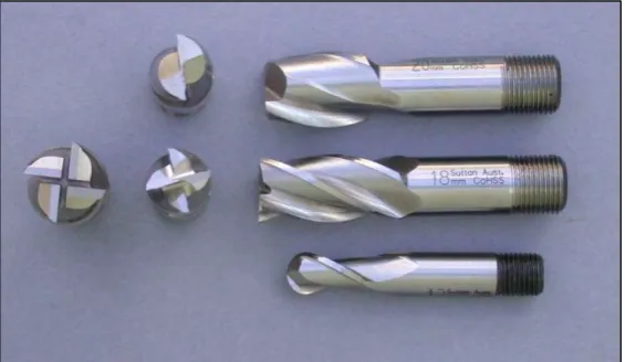
The end milling cutters need to have teeth on the end and periphery. A larger end milling end cutter is mounted on arbor while the smaller ones have a shank for chuck or direct spindle mounting. The end milling cutter is used to creation of keyways, slots and recessed. It also can used to mill angles, edges and shoulders of work piece. (Milling machine operation, n.d). There are several types of end milling cutter are shown in Figure 2.3 above.
[image:24.595.182.465.508.672.2]