UNIVERSITI TEKNIKAL MALAYSIA MELAKA
DESIGN OPTIMIZATION OF CAR JACK USING FINITE
ELEMENT ANALYSIS
This report submitted in accordance with requirement of the Universiti Teknikal Malaysia Melaka (UTeM) for the Bachelor Degree of Manufacturing Engineering
(Manufacturing Design) with Honours
by
NURIN AIFAA BINTI ZAMRI B051210018
930605-14-5124
UNIVERSITI TEKNIKAL MALAYSIA MELAKA
BORANG PENGESAHAN STATUS LAPORAN PROJEK SARJANA MUDA
TAJUK: Design Optimization of Car Jack using Finite Element Analysis
SESI PENGAJIAN: 2015/16 Semester 2
Saya NURIN AIFAA BINTI ZAMRI
mengaku membenarkan Laporan PSM ini disimpan di Perpustakaan Universiti Teknikal Malaysia Melaka (UTeM) dengan syarat-syarat kegunaan seperti berikut:
1. Laporan PSM adalah hak milik Universiti Teknikal Malaysia Melaka dan penulis. 2. Perpustakaan Universiti Teknikal Malaysia Melaka dibenarkan membuat salinan
untuk tujuan pengajian sahaja dengan izin penulis.
3. Perpustakaan dibenarkan membuat salinan laporan PSM ini sebagai bahan pertukaran antara institusi pengajian tinggi.
4. **Sila tandakan (/)
SULIT
TERHAD
TIDAK TERHAD
(Mengandungi maklumat yang berdarjah keselamatan atau kepentingan Malaysiasebagaimana yang termaktub dalam AKTA RAHSIA RASMI 1972)
(Mengandungi maklumat TERHAD yang telah ditentukan oleh organisasi/badan di mana penyelidikan dijalankan)
Alamat Tetap:
No. 32, Jalan Suasana 4/2B Bandar Tun Hussein Onn 43200 Cheras, Selangor
Tarikh: _________________________
Disahkan oleh:
Cop Rasmi:
Tarikh: _______________________
Tarikh: _______________________
** Jika Laporan PSM ini SULIT atau TERHAD, sila lampirkan surat daripada pihak berkuasa/organisasi berkenaan dengan menyatakan sekali sebab dan tempoh laporan PSM ini perlu dikelaskan sebagai SULIT atau TERHAD.
DECLARATION
I hereby, declared this report entitled “Design Optimization of Car Jack using Finite Element Analysis” is the results of my own research except as cited in
references.
Signature : ………
Author’s Name : Nurin Aifaa binti Zamri
APPROVAL
This report is submitted to the Faculty of Manufacturing Engineering of UTeM as a partial fulfillment of the requirements for the degree of Bachelor of Manufacturing Engineering (Manufacturing Design) with Honours. The member of the supervisory is as follow:
………
i
ABSTRAK
ii
ABSTRACT
iii
DEDICATION
iv
ACKNOWLEDGEMENT
v
TABLE OF CONTENT
Abstrak i
Abstract ii
Dedication iii
Acknowledgement iv
Table of Content v
List of Tables viii
List of Figures ix
List of Abbreviations, Symbols and Nomenclatures xi
CHAPTER 1: INTRODUCTION 1
1.1 Background 1
1.2 Problem Statement 4
1.3 Objectives 5
1.4 Scope of Project 5
CHAPTER 2: LITERATURE REVIEW 7
2.1 Introduction 7
2.2 Car Jack 7
2.2.1 Mechanical Jack 8
2.2.1.1 Scissor Jack 8
2.2.1.2 Screw Jack 9
2.2.2 Hydraulic Jack 10
2.2.3 Pneumatic Jack 12
2.3 Material of Car Jack 13
2.3.1 Factors in Material Selection 13
2.3.1.1 Strength 14
2.3.1.2 Weight 14
2.3.1.3 Ease of Manufacturing 14
2.3.1.4 Cost and Availability 14
vi
2.3.2.1 Steel 15
2.3.2.2 Aluminium 17
2.4 Compact Cars 18
2.4.1 Perodua Myvi 18
2.5 Computer Aided Design (CAD) 19
2.5.1 Element of CAD System 20
2.5.2 CAD Software 21
2.5.2.1 SolidWorks 21
2.5.3 Advantages of CAD 23
2.6 Finite Element Analysis (FEA) 24
2.6.1 History of FEA 26
2.6.2 Procedures of FEA 27
2.6.2.1 Pre-processing 27
2.6.2.2 Solution 28
2.6.2.3 Post-processing 28
2.6.3 Advantages of FEA 29
CHAPTER 3: METHODOLOGY 30
3.1 Introduction 30
3.2 Project Flow Chart 30
3.3 Phase of Methodology 33
3.3.1 Planning Phase 33
3.3.2 Design Phase 33
3.3.3 Analyse Phase 33
3.3.4 Optimize and Analyse Phase 34
3.3.5 Presentation and Report Writing 34
3.4 Existing Designs 34
3.4.1 Design 1 35
3.4.2 Design 2 35
3.4.3 Design 3 36
3.4.4 Design 4 36
3.4.5 Design 5 37
vii
CHAPTER 4: RESULT AND DISCUSSION 38
4.1 Introduction 38
4.2 Failure Analysis of Scissor Jack 38
4.3 Detail Design of Scissor Jack 39
4.4 Force Analysis of Scissor Jack 41
4.4.1 Critical Component of Scissor Jack 41
4.5 Finite Element Analysis of Existing Designs 43
4.5.1 Analysis of Design 1 43
4.5.2 Analysis of Design 2 45
4.5.3 Analysis of Design 3 46
4.5.4 Analysis of Design 4 47
4.5.5 Analysis of Design 5 49
4.5.6 Analysis of Design 6 50
4.5.7 Data Analysis of Existing Designs 51
4.6 Optimized Design of Scissor Jack 53
4.6.1 Force Analysis of Optimized Design 54
4.6.2 Finite Element Analysis of Optimized Design 54 4.7 Comparison between Benchmark and Optimized Design 56
4.8 Sustainability Element 58
CHAPTER 5: CONCLUSION AND RECOMMENDATION 59
5.1 Conclusion 59
5.2 Recommendations 60
REFERENCES 62
APPENDICES A Gantt Chart
viii
LIST OF TABLES
2.1 Properties of Low-Alloy Steel 16
2.2 Properties of Cast Aluminium Alloy 17
4.1 Properties of Carbon Steel 40
4.2 Analysis data of Design 1 44
4.3 Analysis data of Design 2 45
4.4 Analysis data of Design 3 47
4.5 Analysis data of Design 4 48
4.6 Analysis data of Design 5 50
4.7 Analysis data of Design 6 51
4.8 Von Mises stress values of the existing designs 52 4.9 Resultant displacement values of the existing designs 52 4.10 Benchmark data analyses of the existing designs 53
4.11 Analysis data of optimized design 55
4.12 Comparison of the analyses’ result between the benchmark and the
optimized design of car jack 56
4.13 Maximum resultant displacement of designs that has only one arm on
ix
LIST OF FIGURES
1.1 Spare tyre in the trunk of a Volvo XC60 2
1.2 Notch underneath the car to fit the car jack 2
2.1 Scissor Jack 8
2.2 Assembly drawing of scissor jack 9
2.3 Cut away illustration of screw jack 10
2.4 Screw Jack 10
2.5 Hydraulic Jack 11
2.6 Mechanism of Hydraulic Jack 11
2.7 Pneumatic Jack 13
2.8 Perodua Myvi 1.3 Standard G 19
2.9 Collaboration in 1979 20
2.10 FEA analysis on a bridge structure 25
3.1 Project Flow Chart 32
3.2 Isometric view of Design 1 35
3.3 Isometric view of Design 2 35
3.4 Isometric view of Design 3 36
3.5 Isometric view of Design 4 36
3.6 Isometric view of Design 5 37
3.7 Isometric view of Design 6 37
4.1 Arm Failure 39
4.2 Bending of the arms 39
4.3 Three tyres are in contact with ground when scissor jack is used on
another one tyre 40
4.4 Forces in Scissor Jack 41
4.5 Free body diagram of the top section of Scissor Jack 42
4.6 Fixtures and force on the arm of Scissor Jack 43
x
4.8 Displacement distribution of Design 1 44
4.9 Stress distribution of Design 2 45
4.10 Displacement distribution of Design 2 45
4.11 Stress distribution of Design 3 46
4.12 Displacement distribution of Design 3 47
4.13 Stress distribution of Design 4 48
4.14 Displacement distribution of Design 4 48
4.15 Stress distribution of Design 5 49
4.16 Displacement distribution of Design 5 49
4.17 Stress distribution of Design 6 50
4.18 Displacement distribution of Design 6 51
4.19 Optimized design of scissor jack 53
4.20 Free body diagram of the top section of the optimized design 54
4.21 Stress distribution of optimized design 55
xi
LIST OF ABBREVIATIONS, SYMBOLS AND
NOMENCLATURES
FEA - Finite Element Analysis
CAD - Computer Aided Design
CAE - Computer Aided Engineering
2D - 2 Dimensional
3D - 3 Dimensional
ANSI - American National Standards Institute
ISO - International Organization for Standardization
DIN - Deutsches Institut für Normung (German Institute for Standardization)
GOST - Gosudarstvennyy Standart (State Standard) JIS - Japanese Industrial Standards
BSI - British Standards Institution
SAC - Standardization Administration of China NASTRAN - NASA Structure Analysis
FE - Finite Element
PSM - Projek Sarjana Muda
kg - Kilogram
mm - Millimetre
m - Metre
s - Second
N - Newton
MPa - Mega Pascal
GPa - Giga Pascal
AISI - American Iron and Steel Institute
F - Force
Min. - Minimum
1
CHAPTER 1
INTRODUCTION
This chapter introduces the background of the project, the problem statement, the objective and also the scope of the project.
1.1 Background
In the repair and maintenance of automobiles, a raise of the vehicle is often necessary in order to get underneath the vehicle or simply to change a tyre. A tool that is used to perform the task is the vehicle jack. Basically, the jack is used in lifting a vehicle above the ground, just enough to enable vehicle maintenances or breakdown repairs. Although the vehicle jack does not play a part in the smooth running of a vehicle engine, yet its presence is important during tyre deflation. Without a jack, a vehicle owner will experience loss in time, money and energy (Dare & Oke, 2008).
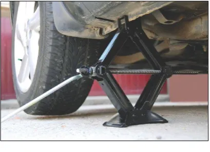
2 A mechanical jack is usually found in the trunk of the car with the spare tyre, as shown in Figure 1.1. Both the scissor jack and the screw jack use an arm for the car owner to raise the car. Oghenekome et al (2014) describes that in order to lift up the car by using scissor jack, the jack is first notched into a hard point on the car's undercarriage. Figure 1.2 shows the notch underneath the car. The lug nuts are then loosened and the arm is turned in a clockwise motion to raise the car. As the arm is turned, a large screw pushes the car up by shortening the distance between the end points of the jack. The mechanism moves along the screw thread which consequently lifts the car up with relatively little effort.
Figure 1.1: Spare tyre in the trunk of a Volvo XC60
(Source:
<http://www.team-bhp.com/forum/official-new-car-reviews/95361-volvo-xc60-test-drive-review.html> 12/09/15)
Figure 1.2: Notch underneath the car to fit the car jack
[image:17.595.217.422.506.654.2]3 The car comes down by reversing the process. The screw is turned counter clockwise and the lug nuts are tightened after the car's tyre has minimal weight on the surface. The jack is then lowered the rest of the way. The scissor jack is called as it is because of the structure of the jack that consists of diagonal metal components that expand and contract in the same way as a pair of scissors. When using a vehicle jack, it must be placed on a flat surface so that the jack does not toppling over, and making the car fell down unexpectedly. Furthermore, the user must ensure that no one is sitting in the car as the car is being lifted up. This is because there is a lot of weight that is supported by the jack with the car itself.
Nowadays, a vehicle jack is an important tool to have in the vehicle due to unknown upcoming incident such as flat tyre in the journey. A flat tyre usually comes at the least unexpected moments, like when going on a long journey, in the highway or in the middle of the woods for instance. As the car is unable to keep moving, the driver has to replace the inflated tyre with the spare tyre. This is a waste of time and energy and even will endanger the driver if he are jacking and changing the tyre in hurry. Working near a vehicle that is supported by a car jack can be fatal, as one does not know when the jack will lose its function and fails.
Therefore, a study on the load that can be lifted by the car jack is crucial to ensure that the specified capacity of the car jack is accurate and dependable so that the user will not experience the unfortunate event of a failed car jack. In order to verify the figure, an analysis called as Finite Element Analysis (FEA) is conducted on the car jack. FEA is a computerized method of simulating and predicting the behaviour of a product that is affected by variety of conditions, such as stresses, vibration, motion, heat, fluid flow, and other physical effects, hence showing whether the product will break or work the way it is supposed to function.
4 result of the analysis is then compared with the analysis from the existing designs of scissor jacks. The optimization is done based on the existing car jacks’ designs in order to improve the quality and hence, the safety features of the car jack.
1.2 Problem Statement
These days, most of the cars were equipped with a scissor jack, as it is smaller and easier to store compared to other jacks. Although the car jack is an important device for the changing of tyre, the use of it may lead to accident and sometimes fatal. According to Iskandar (2008), a serious number of accidents that involve car jacks have been reported all over the world with an average of 160 injuries each year. Injuries varied from amputation to fractures and crush injuries. The major factor that caused the injuries is the insufficient safety features of the car jacks.
Rankine (2007) stated in a news release that a jack is expected to withstand up to 1000 kilograms, but the Consumer Affairs of Government of South Australia has done several tests which showed that the jack fails to work after lifting 250 kilograms. In addition, the tests revealed that when the jack has a lifting weight close to its 1000 kilograms capacity, it may physically break. The tests also proved that the jack has the tendency to deform under the weight it is supposed to hold, thus it does not comply with the requirements of the Australian Standard for vehicle jacks.
In order to encourage improvements in automotive lift technology especially in the area of safety, an organization called as Automotive Lift Institute (ALI) was established. Before, up until late 1990s, car jack manufacturers were permitted to claim that their products were safe although they did not meet any set standard. However after ALI has been established, they cooperate with the American National Standards Institute (ANSI) to ensure that all jacks and lifts satisfy a set number of performance standards in order to be ALI/ANSI certified.
5 current car jacks do not have a lock to secure the position of the jack, or extra beam to withstand the heavy load of the car. Therefore, it can be seen that the improvement in automotive car jack is really needed to make the tool more efficient, reliable, high quality and most importantly high safety features. Hence, this report is prepared to analyse the design of the existing car jacks and then optimize the design so that it is safer to be operated.
1.3 Objectives
The aim of this project is to perform structural analysis on car jack design to determine the best design optimization for the car jack.
This can be accomplish by following these objectives:
To redesign the existing car jacks using SolidWorks software.
To analyse the car jack designs using Finite Element Analysis.
To optimize the car jack design.
1.4 Scope of Project
This project comprises the design, analysis and optimization of car jack.The type of car jack that will be used in this project is scissor jack as it is more common to vehicle users. The capacity of the scissor jack is 500 kg and the jack is targeted to be used with compact cars such as Perodua Myvi which weighs about 970 kg. Perodua MyVi is selected to be the target object as it is used by many people and has been the best-selling car in Malaysia from 2005 to 2010.
6 maximum Von Mises stress and maximum resultant displacement will be chosen as a benchmark.
7
CHAPTER 2
LITERATURE REVIEW
2.1 Introduction
A literature review is a discussion on published materials like books, journals, thesis, articles, reports and conference proceedings. The main purpose of this literature review is to obtain information about the project from the previous researches. This chapter will describe the topics that are related to car jack, car group, Computer Aided Design (CAD) and Finite Element Analysis (FEA).
2.2 Car Jack
A car jack is a device that functions to easily lift all or part of a car above the ground in order to gain access to area underneath the car or to change the tyre. Car jacks normally take advantage of mechanical force to enable an individual to raise a vehicle by manual force (Noor et al., 2008). At present, a variety of car jacks have been produced to lift a vehicle from a ground surface. Iskandar (2008) stated that there are three major types of car jack that have been commercialized for vehicle users, which are the mechanical type, hydraulic type and pneumatic type.
8 2.2.1 Mechanical Jack
Most car jacks that are included as a tyre repair kit in cars are the mechanical type. This is because they are smaller and hence, easier to store compared to other types. Scissor jack and screw jack are two common kinds of mechanical jack (Dare & Oke, 2008).
2.2.1.1 Scissor Jack
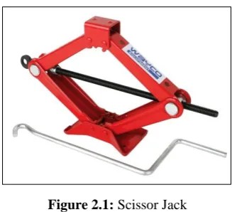
[image:23.595.236.400.440.589.2]Babu (2015) claimed that scissor jacks have been in use since 1930s. A scissor jack is a tool that was designed with a cross-hatch mechanism, just like a scissor, to raise a vehicle off the ground for repairs and maintenance, as shown in Figure 2.1. The jack typically works in a vertical manner as to lift up the vehicle. It opens and folds, exerting pressure to the support beams that make the crossed patterns, thus making the jack to move. Scissor jacks are simple mechanisms that are used to operate on large loads over short distances.
Figure 2.1: Scissor Jack
(Source: <http://www.wayco.co.nz/w1013.htm> 16/09/15)
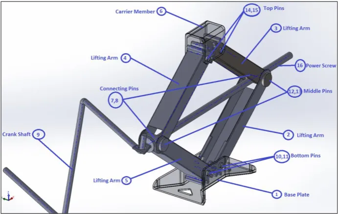
9 According to Bariskan (2014), most scissor jacks are designed in a similar concept that consists of four lifting arms, a base plate, a carrier member, eight connection pins, a power screw and a crank shaft. Figure 2.2 shows the assembly drawing of a scissor jack with the name of the parts.When the crank is rotated, the screw turns, and consequently raises the jack. The screw functions like a gear mechanism. The screw thread, which acts like teeth of a gear, turns and moves the four arms, producing a linear motion. The four arms are all linked at the end with a bolt that allows the corners to fold.
Figure 2.2: Assembly drawing of scissor jack (Bariskan, 2014)
2.2.1.2 Screw Jack