This is a repository copy of
Performance of Fixed-Parameter Control Algorithms on
High-Rise Steel Structures Equipped with Smart Tuned Mass Dampers
.
White Rose Research Online URL for this paper:
http://eprints.whiterose.ac.uk/83768/
Version: Accepted Version
Proceedings Paper:
Demetriou, D, Nikitas, N and Tsavdaridis, KD (2015) Performance of Fixed-Parameter
Control Algorithms on High-Rise Steel Structures Equipped with Smart Tuned Mass
Dampers. In: UNSPECIFIED The 8th STESSA Conference on Behaviour of Steel
Structural in Seismic Areas, 01-03 Jul 2015, Shanghai, China. .
[email protected]
https://eprints.whiterose.ac.uk/
Reuse
Unless indicated otherwise, fulltext items are protected by copyright with all rights reserved. The copyright
exception in section 29 of the Copyright, Designs and Patents Act 1988 allows the making of a single copy
solely for the purpose of non-commercial research or private study within the limits of fair dealing. The
publisher or other rights-holder may allow further reproduction and re-use of this version - refer to the White
Rose Research Online record for this item. Where records identify the publisher as the copyright holder,
users can verify any specific terms of use on the publisher’s website.
Takedown
If you consider content in White Rose Research Online to be in breach of UK law, please notify us by
PERFORMANCE OF FIXED-PARAMETER CONTROL ALGORITHMS ON
HIGH-RISE STRUCTURES EQUIPPED WITH SEMI-ACTIVE TUNED MASS
DAMPERS
Demetris Demetrioua*, Nikolaos Nikitasa and Konstantinos Daniel Tsavdaridisa
a
University of Leeds, School of Civil Engineering, United Kingdom
[email protected], [email protected], [email protected]
Keywords: semi-active dampers, vibration control algorithms, wind excitation, high-rise buildings
Abstract. The present study investigates the performance of fixed parameter control (direct output and
full state feedback) algorithms on wind excited high-rise structures equipped with semi-active tuned mass dampers (STMD) of variable damping. It has been demonstrated that when the same auxiliary semi-active device is used, the algorithms that increase significantly the performance of the controlled structure do so at the expense of damper strokes. On the contrary, when the maximum damper strokes are capped to a certain limit, there may be a case where what was found to be the more conservative algorithms may allow for similar performance gains while at the same time minimising the required number/size of the devices and force demands.
1 INTRODUCTION
Since the introduction of the tuned mass damper (TMD) to the engineering community by Frahm in 1911 [1], a large number of studies have been published validating the applicability and effectiveness of TMDs on high-rise structures. In an attempt to improve further the effectiveness and flexibility of the device, researchers across the world have successfully altered the original design by incorporating sophisticated passive, semi-active and active elements. While the approach of upgrading the performance of the TMD using passive elements is reasonable from a technological, practical and cost perspective [2], this is not true when it comes to semi-active and active control elements. As a matter of fact, semi-active components available for use in structures comprising of variable damping semi-active tuned mass dampers (STMDs), are mostly limited to magnetorheological (MR) and electrorheological (ER) elements, the cost of which is prohibitive especially when considering the size and number required. Due to these limitations, an attempt has been made to improve the performance of a semi-actively controlled system via the selection of an appropriate control algorithm. Amongst the most popular control algorithms developed for the case of the STMDs, groundhook control [3-6], clipped optimal control [7, 8], and bang-bang control [9, 10] have been selectively used in literature. In an attempt to quantify the performance of these algorithms, the authors of [4, 6, 11] conducted comparative studies on structures equipped with STMD at different fixed parameter algorithm configurations. Although these studies agree on the performance gains arising from the different algorithms, it is realized that either due to the nature of the external perturbation (white noise or earthquake) or either due to the system’s geometric and dynamic properties (low-rise and high-frequency structures), the authors did not take into account one main performance limiting factor, the stroke of the damper, thus their results might not be transferable to the case of wind excited high-rise structural systems.
D. Demetriou, N. Nikitas, and K.D. Tsavdaridis
2 MODELING THE STMD CONTROLLED SYSTEM
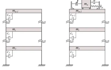
A single TMD’s operational principle can be explained by considering a simple n -DOF sway frame as the one depicted in Fig.1. The dynamic behaviour of such a system when subjected to an arbitrary disturbance is fully captured by its matrix equation of motion:
Mx(t)Cx(t)Kx(t)Bu(t)Dd(t) (1)
where M , C and K are the n n mass, damping, and stiffness structural matrices respectively; x(t) and d(t) are in order the displacement, and external force n 1 column vectors; u(t) is the single scalar control force and B and D are the n n influence matrices assigning the control and external force contributions respectively to the individual DOFs. For each DOF being the displacement of the ith mass, M trivially becomes diagonal, while for the pure viscous damping considered (and connections as in Fig. 1) the damping matrix C attains a form identical to the symmetric stiffness matrix K . Without any loss of
generality the mass damper device is attached to the (n 1) th DOF and its motion constitutes
[image:3.454.145.327.251.367.2]then DOF. th
Fig. 1. Sway n-storey sway frame with and without the semi-active TMD device
The matrix Eq. (1) could describe a system equipped with any type of dynamic control device. The difference between passive, active and semi-active schemes would exclusively be captured by the nature of the control force u(t) . It would be probably more appropriate for this case to term u(t) as interaction force, yet for presentation ease the term control is used throughout. To facilitate the derivation of a semi-active control force, it would be beneficial to first consider the case of a purely passive TMD. When the TMD is attached to the system of interest, the u(t) , takes the form of a purely passive action, u (t)p resulting solely from the motion of the absorber’s mass. This passive force which couples the
damper to the rest of the system can be mathematically expressed as:
r r
u (t)p cpx (t)kpx (t) (2)
In the above equation, c is the constant scalar damping coefficient and p k is the constant scalar p
spring stiffness of the TMD, whilex (t) andr x (t) are respectively the relative velocity and displacement r
between the n and th (n 1) thDOFs. It should be also noted that the n-element B becomes
0... 1 1
T.When an active control system is considered, the control force takes the form of a desired action, u (t)a determined via a control algorithm. For an active mass damper (AMD), the desired force is the
remain unaltered and the desired interaction force, u (t)a has already been calculated by the control algorithm, the required actuation force, f (t)a can be readily determined by:
r r
u (t)a cpx (t)kpx (t)f (t)a (3)
The final step of the derivation of the semi-active control force involves the calculation of a force that can be physically realized by the semi-active device. For the case herein where a system able to only
“consume” energy is considered the semi-active control force, u (t)sa is calculated by [7]:
r 1 sgn[f (t)x (t)] u (t) f (t)
2
a
sa a (4)
1 for q 0sgn(q )
q 1 for 0
a (5)
where qais the power product f (t)x (t)a r . When a variable damping (VD) STMD is considered, the way of achieving optimum performance is by timely adjusting its damping coefficient within bands for the required control force to be reached. By referring back to the system presented in Fig. 1, one can express the semi-active damping force contribution asc (t)x (t)sa r , with c (t)sa 0. Updating Eq. (3), the overall control force provided at each time instant can be expressed mathematically as
r r
u (t)a ( c (t)sa cp)x (t)kpx (t) (6)
In Eq. (6) the time varying semi-active damping coefficient, c (t)sa is the only unknown, which makes its variation calculation straightforward.
3 CONTROL METHODS ENSEMBLE
In feedback-controlled systems, the behaviour of the control device is determined using algorithms. Both classical and modern feedback algorithms are classified into two broad categories: 1) fixed parameter and 2) adaptive parameter. The former category, as the name suggests, refers to fixed control parameters and gains, while the latter allows for some adaptation or training during control. Fixed parameter controllers are further divided into two subcategories, namely: 1) direct output feedback (DOFB) and 2) full state feedback (FSF) controllers. The main difference of the two is that the first calculates control gains from direct measurements of the system’s output while the latter calculates control gains based on the assumption of full state knowledge. This study concentrates solely on the most popular fixed parameter control algorithms namely: Groundhook, PID, LQR, and bang-bang control.
3.1 Direct output feedback control
According to modern control theory, the vibration mitigation capacity in controlled systems is upgraded using full state feedback, which requires the availability of all the structural system states. Because of the large number of DOFs in high-rise structures, and the subsequent impracticality of measuring the displacements and velocities corresponding to all degrees of freedom, DOFB controllers which make use of limited measurements became necessary [12]. Here, the common problem of limited-state feedback is dealt without the requirement of limited-state reconstruction that complicates operations.
3.1.1 On / off control
D. Demetriou, N. Nikitas, and K.D. Tsavdaridis
and a minimum value. The determination of whether a high or low value is required depends exclusively on the partial knowledge of the states of the system. A great example of such an on/off control is found in the famous skyhook control scheme. It is noteworthy that algorithms developed upon the skyhook control are mostly practised in automotive engineering (e.g. active suspension systems) in an attempt to control the sprung mass (i.e. the mass supported by the active damper). On the contrary, in civil engineering structures, the main aim is to control the unsprung mass (i.e. the mass supporting the active damper) as shown in Fig. 1, making the skyhook option unattractive. The algorithm developed based on the modification of the skyhook control for controlling the unsprung mass is known as groundhook control.
In a groundhook control scheme, the directionality condition of the forces needs to be examined in order to determine whether high or low damping is required. Depending on the motion of the mass of the damper and the structure and without the loss of generality, four cases are identified and damper forces are calculated in accordance to Table 1 [13]:
Table 1. Groundhook Control Logic Sign
Conventions
Damper Conditions
Desired Damping State Extension Off Compression On
Extension On Compression Off
In summary, this velocity based groundhook (VBG) control logic is mathematically captured by:
xn 1 rx 0 max, xn 1 rx 0 min (7)
Alternatively, it is possible to replace the unsprung mass velocity by a primary system displacement term, resulting to displacement based (DBG) control, mathematically expressed as:
n 1 r
x x 0 max, xn 1 rx 0 min (8)
3.1.2 PID control
A PID controller works by calculating appropriate control actions based on a feedback error e(t) . For a negative feedback system, the error e(t) is defined as the difference between the output signal, y(t) to a desired reference signal r(t) . Using the textbook version of the PID controller, the desired control inputs that minimize the feedback error are calculated by [14]:
tf
0
de(t) u (t) Ge(t) G e(t)dt G
dx
a in d (9)
The objective is to tune the gains G,G ,Gin dsuch as given a feedback error at any time within the
control time tf the generated inputs will result into enhanced closed-loop system behaviour.
3.2 Full state feedback control
Full state feedback also referred to as pole assignment methods are abundant in modern control theory [15]. Such algorithms perform on the simple basis of altering the eigenvalues of the system in such a way that either its damping capacity is increased or its frequencies move out of the resonant range. The first step into achieving desired performance is to make an estimation of all the states of the system using techniques such as Kalman filter or dynamic observer (i.e. Luenberger’s observer). With the states in-hand the idea is to determine a gain matrix G that generates a control feedback according to:
u(t) GX (10)
n 1 r
x 0, x 0
n 1 r
x 0, x 0
n 1 r
x 0, x 0
n 1 r
3.2.1 Optimal control
Optimal controllers minimize a quadratic performance index through manipulation and optimization of the control vector u(t) . The performance index used in structural control applications when working with the state space formulation is defined as [16]:
tf
T T
0
J
[x (t)Qx(t)u (t)Ru(t)]dt (11)where Q and R are weighting matrices relating to the trade-off between effectiveness and energy consumption. Manipulating Q and R , better disturbance rejection can be achieved at the expense of control effort and vice versa. Once the weighting matrices have been obtained, the gain is calculated by:
1 T 1 K R B P
2
(12)
where P is a matrix found after the algebraic Riccati equation.
3.2.1 Optimal and suboptimal/Lyapunov bang-bang control
The objective of bang-bang control is to also minimise a quadratic performance index (for more see [9]). It is worth noting, that the optimal control action is of bang-bang/on-off nature, i.e. it moves from a maximum to a minimum value at a certain condition. It is easy to realise that obtaining the control actions, one needs to solve online a differential equation, which will evidently increase the delays in the system and potentially degrade the overall performance. Alternatively, the control actions can be obtained by the so-called suboptimal bang-bang control. Where no on-line solution of differential equations is required. The reader is referred to [9, 10] for the complete derivation of the optimal and suboptimal bang-bang law that is followed in this paper.
4 NUMERICAL INVESTIGATION
4.1 Structural configuration
To illustrate the effectiveness of the different algorithms at alleviating structural response, the 76-storey benchmark wind-prone structure proposed by Yang et al. [17] was considered. The structure is excited by across wind loading for a duration of 900s, enough to establish stationary response. In this study, two vibration mitigation alternatives are practised, namely: passive (TMD) and semi-active (STMD) controlled structures were used to demonstrate the performance gains of the variation in the control algorithm.
D. Demetriou, N. Nikitas, and K.D. Tsavdaridis
Fig. 2. Indicative response results for the TMD and for the variously controlled STMD equipped structure
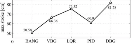
Fig. 3. Damper strokes for the different algorithms studied in Fig. 2
4.2 Evaluation criteria
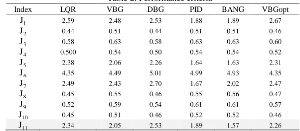
The comparison of the different control algorithms was based on the stationary response properties of the different control structures. From the response time histories, the rms and peak accelerations and displacements at different storeys were obtained. From the obtained values, eleven performance criteria were identified. The reader is referred to [17] for more details on these performance indices. From the defined criteria,J , J ,.., J the smaller the index, the better the performance. 1 2 11
5 SIMULATION RESULTS AND CONCLUSIONS
The two structural configurations consisting of passive, previously evaluated against the uncontrolled scenario [17], and semi-active control devices were scrutinised and five different control algorithms for the semi-active component were compared. Fig. 2 summarizes the peak and rms (displacement and acceleration) responses at every floor; alongside the relevant maximum damper stroke is given in Fig. 3. It is evident that for given control device configurations (i.e. same min/max damping coefficients) not every algorithm managed to retain the structure’s acceleration response below a predefined limit of 15cm/s2. However, it is also evident that the performance of the STMD device is strongly linked to its stroke. As a matter of fact, the larger the allowable stroke of the damper, the better the vibration attenuation capacity of the system. In Table 2, the performance index J is indicative of the effect of the 11
algorithms on the damper’s stroke; the lower the J , the more conservative an algorithm and the more 11 there is margin for increasing the stroke and hence the system’s performance.
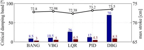
[image:7.454.125.340.235.308.2](i.e. 10%); denoted as VBGopt in Table 2. As a matter of fact, not only the performance of the VBG is closer to the DBG but also the maximum stroke of the VBG controlled device remains considerably lower than the DBG device (73 cm compared to 82 cm). Similarly, altering the maximum damping coefficient for the PID and LQR controlled STMD from 20% to 10% identical performance gains can be observed. The interplay of stroke and damping ranges is shown in Figs. 4, 5, which repeats the comparison of Figs. 2, 3 for when the allowable stroke is capped. Recapitulating, given fixed auxiliary device parameters (max/min damping coefficients) the algorithm with the higher J11 performance index would always be the least conservative algorithm since its performance merit arises from a substantial increase in the
[image:8.454.73.398.228.351.2]damper’s stroke. On the other hand, when the maximum damping coefficient is lowered and consequently the size and number of ER or MR dampers is reduced, the more conservative algorithms (lowerJ ) 11 attains similar performance at the expense of lower strokes. Obviously, the question of what is the best algorithm for a given device would now change to a question of which algorithm can be used to minimise the number, size and force demands of the auxiliary device while maintaining good closed loop performance within the predefined stroke limits.
Fig. 4. Comparison of different control algorithms of the STMD when the allowable damper stroke is capped
Fig. 5. Damping max-min ranges and damper strokes for the STMD control scenarios within Fig.4
[image:8.454.123.356.387.469.2]D. Demetriou, N. Nikitas, and K.D. Tsavdaridis
Table 2. Performance criteria
Index LQR VBG DBG PID BANG VBGopt
1
J 2.59 2.48 2.53 1.88 1.89 2.67
2
J 0.44 0.51 0.44 0.51 0.51 0.46
3
J 0.58 0.63 0.58 0.63 0.63 0.60
4
J 0.500 0.54 0.50 0.54 0.54 0.52
5
J 2.38 2.06 2.26 1.64 1.63 2.31
6
J 4.35 4.49 5.01 4.99 4.93 4.35
7
J 2.49 2.43 2.70 1.67 2.02 2.47
8
J 0.45 0.55 0.46 0.55 0.56 0.47
9
J 0.52 0.59 0.54 0.61 0.61 0.57
10
J 0.45 0.51 0.46 0.52 0.52 0.46
11
J 2.34 2.05 2.53 1.89 1.57 2.26
6 REFERENCES
[1] Frahm H. Device for damping vibration of vodies. United States: US Patent; 1911.
[2] Marian L, Giaralis A," Optimal design of a novel tuned mass-damper-inerter (TMDI) passive vibration control configuration for stochastically support-excited structural systems", Probabilistic Engineering Mechanics. 2014.
[3] Koo JH, Murray TM, Setareh M, "In search of suitable control methods for semi-active tuned vibration absorbers", Journal of Vibration and Control. 2004;10:163-74.
[4] Ji HR, Moon YJ, Kim CH, Lee IW," Structural Vibration Control Using Semiactive Tuned Mass Damper". The Eighteenth KKCNN Symposium on Civil Engineering-KAIST6. Taiwan2005.
[5] Liedes T, "Improving the Performance of the Semi-Active Tuned Mass Damper", Oulu: University of Oulu; 2009.
[6] Kang J, Kim H-S, Lee D-G," Mitigation of wind response of a tall building using semi-active tuned mass dampers", The Structural Design of Tall and Special Buildings. 2011;20:552-65. [7] Hrovat D, Barak P, Rabins M, "Semi-Active Versus Passive or Active Tuned Mass Dampers For Structural Control", Journal of Engineering Mechanics. 1983;109:691-705.
[8] Pinkaew T, Fujino Y, "Effectiveness of semi-active tuned mass dampers under harmonic excitation" Engineering Structures. 2001;23:850-6.
[9] Wu Z, Soong TT.,"Modified Bang-Bang Control Law For Structural Control Implementation", Journal of Engineering Mechanics. 1996;122:771-7.
[10] Jansen LM, Dyke SJ.,"Semi-Active Control Strategies for MR Dampers: A Comparative Study", Engineering Mechanics. 2000;126:795-803.
[11] Patrascu M, Dumitrache I, Patrut P," A comparative study for advanced seismic vibration control algorithms" UPB Scientific Bulletin. 2012;74.
[12] Chung LL, Lin CC, Chu SY," Optimal Direct Output Feedback of Structural Control", Journal of Engineering Mechanics. 1993;119:2157-73.
[13] Koo JH, "Using Magneto-Rheological Dampers in Semiactive Tuned Vibration Absorbers to Control Structural Vibrations". Blacksburg,Virginia: Virginia Polytechnic Institute and State University; 2003.
[14] Astrom KJ, Murray RM. "Feedback Systems-An introduction for scientists and Engineers". New Jersey 08540: Princeton University Press; 2012.
[15] Cheng FY, Jiang H, Lou K. "Smart structures: Innovative systems for seismic response control". New York: Taylor & Francis Group; 2008.
[16] Soong TT. "Active structural control: Theory and practice". New York: John Wiley & Sons,Inc.; 1990.