UNIVERSITI TEKNIKAL MALAYSIA MELAKA
DEVELOPMENT OF AN AUTOMATED GUIDED VEHICLE
This report submitted in accordance with requirement of the Universiti Teknikal
Malaysia Melaka (UTeM) for the Bachelor Degree of Manufacturing Engineering
(Robotics and Automation)(Hons.)
by
MUHAMMAD ZULHELMI BIN AHMAD
B051010052
880206025069
FACULTY OF MANUFACTURING ENGINEERING
ABSTRAK
Tujuan projek ini adalah untuk rnengkaji dan rnernbangunkan sebuah kenderaan dipandu secara autornatik (AGV) yang boleh rnengangkat dan rnenarik troli seberat 300kg secara autornatik rnenggunakan navigasi garisan. Turnpuan kawasan kerja AGV adalah di kawasan gudang . Oleh itu projek ini hanya te11umpu kepada pembangunan dan prestasi AGV. Di dalam projek ini, reka bentuk AGV menggunakan SolidWork 2012. Empat roda mecanum dengan I 20W arus terus (DC) berus motor telah digunakan untuk menggerakan AGV dan bagi sistem navigasi digunakan penderia penentukuran rnaju. Penderia ini diletakan di hadapan AGV. Untuk penilaian prestasi AGV, data telah dikurnpulkan dengan menandakan kawasan yang AGV telah lalui untuk rnencapai matlarnat sasaran dua titik di kedudukan (titik bermula) ke titik yang lain (titik berakhir). Data yang telah dikurnpulkan dan derekodkan setiap 40cm untuk mendapatkan pergerakan AGV sebenar. Untuk memastikan kejayaan penilaian navigasi, proses pengukuran data akan dijalankan sebanyak 5 kali. Hasiln simulasi ditunjukan dalam gambar,jadual dan garf. Pada rnasa yang sarna AGV boleh rnengangkat dan menunda troli 300kg.
20
ABSTRACT
fJ
The purpose of this project is to study and develop an Automated Guided Vehicle
(AGV) that can lift and tow a trolley 300 of kg weight automatically using the line
navigation. The focus waking area of AGV is at the warehouse. Therefore,this project
focus on the development and performance of AGV . In this project, the SolidWork was
used in designing the AGV. Four mecanum wheels with 120W DC brush motor were
used to move the AGV and an Advance Calibration Sensor was used as the guidance
system. This sensor was placed at the front of AGV. In archive the AGV performance,
data was collected by marking the area that AGV in achieving to reach a target goal of
two position point (start point) to another point (last point). Data was recorded every
40cm to get the actual movement of AGV. In ensuring the success of navigation, the
process of data measurement was conducted 5 times. The results are shown in pictures, tables and graph. At the same time the AGV can lifting and towing a trolley 300 kg.
D
E
DI
CA
TION
I dedicate this report to my beloved parents Ahmad bin Hj Bahari and Zaiton bt Awang. Not forgotten, my supervisor, Dr. Fairul Azni bin Jafar and our mechatronic laboratory technician , Mr Muhamad Asari bin Abdul Rahim, lecturers Mr Mahasan Mat Ali, and my friends especially Rozaimi bin Sabri and Mohd Aidil bin Othman for giving the assistant and supports in completing this project. Not forgotten language advisors Madam Teh Zanariah binti Mohd Raus and Madam Nadiah binti Zainal Abidin are not give up for teaching and guiding me about writing project reports ways until successfully.
22
ACKNOWLEDGEMENT
m
ALI Praise to Allah and prayers and peace be upon Muhammad Rasulullah S.A.W. ir · Qf all, I would lik thanks and appreciation ~. Fairul Aznilllo
· consistent iguidancc scarification to help and encouraged to finish this Final Year Project I. From the bottom of my heart I am so grateful to Dr. Fairul Azni bin Jafar as my supervisor. Thanks to my family who always support me in term or money, advice, and others. Special thanks also dedicated to my friends especially Rozaimi bin Sabri and Mohd Aidil bin Othman for help me a lot during the progression of project. I am grateful for any kind of help received from others directly or indirectly during the process of my Final Year Project 2.
TABLE OF CONTENTS
Abstrak
. tract
Dedication Acknowledgement Table of Content List of Tables List of Figures
List Abbreviations, Symbols and Nomenclatures
CHAPTER 1: INTRODUCTION
I. I Background
1.2 Problem Statement 1.3 Objectives
1.4 Scope
1.5 Organisation
CHAPTER 2: LITERATttfjE REVIEV\
g_.r
futroduction of the Automated Guided Vehicle (AGV) !2.2 Type of Automated Guided Vehicle (AGV)2.2. I Driverless Trains
2.3
2.4
2.2.2 Pallet Trucks
2.2.3 Unit Load Carriers
. . V Applications
g,l, I Storage
l!!lSI
Distribution!2.3.2 Assembly Line Application
!2.3.3 Flexible Manufacturing Systems
Navigation of the Automated Guided Vehicles (AGV)
2.4.1 Line Following
2.4.2 Magnetic Guidance
©
Universiti Teknikal Malaysia Melaka2.4.3 Wire Guidance 16
2.4.4 Laser Guidance 16
2.4.5 Vision Guidance 17
2.4.6 Localization 18
2.5 Summary 19
El
CHAPTER 3: METHODOLOGY
3.1 Introduction 21
3.2 Idea Collections 22
3.2.l Review of AGV 22
3.2.1. J Current AGV 23
3.2.2 Identify Requirement 24
3.3 Conceptual Design 25
3.3.I Concepts Generations 26
3.3.2 Concepts Selection 27
3.3.3 Concepts Development 28
3.4 Development 30
3.4.1 Hardware structure development 31
3.4.1.1 Frame body fabrication 31
3.4.1.2 Motor and Wheels assembly 32
3.4.2 Electrical parts development 33
3.4.2.1 Electronic circuit design 34
3.4.2.2 Manual Wiring 38
3.4.2.3 Functionality 39
3.4.3 Software Algorithm Design 39
3.5 Testing and Analysis 40
3.5.1 Path of AGV 40
3.5.2 Navigation Method 41
3.5.3 Analysis 42
3.6 Materials 43
3.7 Summary 44
CHAPTER 4: DESIGN AND DEVELOPMENT
Mechanical Structure
4.2
4.3
4.1.1 Mechanical Fabrications
4.1.1.1 AGY Base Fabrications
4.1. 1.2 Bracket DC Motor Fabrication
4.1.1.3 Key Hub Mecanum Wheel Fabrication
4.1.1.4 40mm bar Bracket Fabrication
4.1.1.5 Electrical Base Plate Fabrication
Control System
4.2. l Circuit Design
4.2.2 Power Supply Circuit
Programming
CHAPTER 5: RESULTS AND ANALYSIS
5 .1 Experiment Requirement
5.2 Experiment I (Straight path without load)
5.2.I I st Run (Straight path without load)
5.2.2 2nd Run (Straight path without load)
5.2.3 3rd Run (Straight path without load)
5.2.4 4th Run (Straight path without load)
5.2.5 5th Run (Straight path without load)
5.3 Experiment 2 (U-Shape path without load)
5.3.1 I st Run (U-Shape path without load)
5.3.2 2nd Run (U-Shape path without load)
5.3.3 3rd Run (U-Shape)
5.3.4 4th Run (U-Shape path without load)
5.3.5 5th Run (U-Shape path without load)
5.4 Experiment 3 (Straight path with 300kg load)
5.4.1 1st Run (Straight path with 300kg load)
5.4.2 2nd Run (Straight path with 300kg load)
5.4.3 3rd Run (Straight path with 300kg load)
©
Universiti Teknikal Malaysia Melaka5.5
5.6
5.7
m
5.4.4 4th Run (Straight path with 300kg load)
5.4.5 5th Run (Straight path with 300kg load)
Discussion
5.5.1 Experiment Analysis (straight without load)
5.5.2 Experiment Analysis (U-Shape without load)
5.5.3 Experiment Analysis (straight with load
Problems and countermeasure
Summary
CHAPTER 6: CONCLUSION & FUTURE WORK
6.1 Conclusion
6.2 Future wor)\ (RecommendationO
REFERENCES
APPENDICES
LIST OFT ABLES
3.1 Concept evaluation 3.2 Bill of material
4.1: Common Metric Tap Drill Sizes.
5.1 Data tabulation for I st experiment I
5.2 Data tabulation for 2nd experiment 1 74
5.3 Data tabulation for 3rd experiment I 76
5.4 Data tabulation for 4th experiment I 78
5.5 Data tabulation for
s•h
experiment 1 805.6 The data tabulation for !st experiment 2 83
5.7 The data tabulation for 2nd experiment 2 85
5.8 The data tabulation for 3rd experiment 2 88
5.9 The data tabulation for 4'" experiment 2 90
5.10 The data tabulation for 4th experiment 2 92
5.11 The data tabulation for 1st experiment 3 95
5.12 The data tabulation for 2nd experiment 3 97
5.13 The data tabulation for 3rd experiment 3 99
5.14 The data tabulation for 4th experiment 3 101
5.15 The data tabulation for 5th experiment 3 103
LIST OF FIGURES
2.1 AGV used in internal logistic 7
2.2 Driverless automated guided trains 8
2.3 AGV pallet trnck 9
2.4 AGV Uni1 Load Carriers 10
2.5 Example of navigation systems 14
2.6 Line 1racking navigaiion principle on 1he line follower robot 15
3.1 Overall nowchar1 of the project. 21
3.2 Idea colleciion now chart. 22
28
3.3 AGV al warehouse Johnson Controls. 23
3.4 Trolley wilh 300kg weight 24
3.5 Concepmal Design flow chart. 25
3.6 Concepl genera1ions of the AGV 26
3.7 lsornetric vie\V .28
3.8 From View
29
3.9 Side View
3.10 Top View 29
3.11 Development of AGV flow chart 30
3.12 Hardware structure flow chan 31
3.13 Aluminium profile and bracke1s .32
3.14 Brackels anach on aluminium profiles 32
3.15 120W DC brush mo1or and mecanum wheels 33
3.16: Elcc1rical parl developmem process flow chart 33
3.17: Electronic circuil block diagram of AGV. 34
3.18: Motor Driver MD30B. 35
3.19: SK40C. 35
3.20: PIC 16F877 A Microcon1roller 36
3.21: Advanced auto-calibrating line sensor. 37
3.22: Electric car jack. 37
3.23: SLA battery and battery charger 38
3.24: AMC Foyer (FKP laboratory). FKP Building 40
3.25: Path of AGV 41
3.26: Navigation error 42
4.1: Design of AGV
46
4.2: Actual AGV. 46
4.3: Cutting aluminium profile using handsaw 47
4.4: Connection process of aluminium profiles using M6 screw and bracke t48
4.5: BaseofAGV. 48
4.6: Design de motor bracket 49
4.7: Culling GI plale using Laser Culling Machine 50
4.8: GI plalc had been cul using Laser Culling Machine 50
4.9: Bending GI plate process LL~ing Manual Banding Machine 51
4.10: lns1alla1ion DC molOr to GI pla1e 51
4.11: Design of key hub of mecanum wheel .52
4.12: Cutting mild steel bar using Bandsaw Machine. 53
4.13: Fabrica1ion key hub using CNC Machine 53
4.14: lnstalla1ion of key hub wilh l2mm bearing pillow block to mecanum wheel 10 base AGY.54 4.15: lnstalla1ions of four key hub with eighl l2mm bearing pillow block for four mecanum wheels to
base AGY. 54
4.16: lnstallalions four key hub. eighl l2mm bearing pillow block. and four mechanum wheels 10 four
4.17: 4.18: 4.19: 4.20 4.21 4.22: 4.23: 4.24: 4.25: 4.26 4.27: 4.28: 4.29: 4.30: 4.31: 4.32: 4.34: 4.35:
DC motors. 55
Conneclion between DC molor and key hub using I 2mm coupler Design of bracket.
12mm cylinder bar housing. : Face milling.
: Drilling. Tapping method.
lnslallation bracket and l2mm linear motor ball bearing slides to 12mm cylinder bar.
Design of elec1ronic part plales
Cutting acrylic 3mm using Laser Culling Machine shows installation electronic pans to 3mm acrylic plates
Overall Of Circuit Design
Overview of PIC wiring installation Wiring of eighl baneries schematic diagram
Wiring 1wo baueries 24Y value
2V value
Recharging baneries using adapter
Line Following in Programming Part.
©
Universiti Teknikal Malaysia Melaka5.1: The actual path 69
5.2: Graph 69
5.3: The actual straight path 70
5.4: The l" experiment result (straight). 71
5.5: The data of movement AGV error for 1" Run 72
5.6: The 2nd experiment result (straight). 73
5.7: The data of movement AGV error for 2"d experiment 74
5.8: The 3rd experiment result (straight) .75
5.9: The data of movement AGV error fol' 3rd experiment. 76
5.10: The 4th experiment result (Straight) .77
5.11: The data of movement AGVerror for 4'" experiment 1 78
5.12: The 5th experiment result (straight). 79
5.13: The data of movement AGY error for 5th experiment l. 80
5.14: The actual U-Shape pathway 81
5.15: The I st experiment result (U-Shape). 82
5.16: TI1e data of movemenc AGY e1Tor for I st experimenc 2. 84
5.17: The 2nd experiment result (U-Shape). 84
5.18: The data of movement AGY error for 2"" experiment 2 86
5.19: TI1e 3rd experiment resull (U-Shapc) .87
5.20: The data of movement AGY error for 3'J expe1iment 2 89
5.21: The 4th experiment result (U-Shape). 89
5.22: The daca of movement AGY error for 4th experimenc 2. 91
5.23: The 5th experiment result (U-Shape) 91
5.24: The data of movement AGY error for 5th experiment 2. 93
5.25: The actual straight path 94
5.26: The lsc experiment result (straight with load). 94
5.27: The I st experiment result (straight with load) 96
5.28: The 2"" experiment result (straight with load). 96
5.29: The 2nd experiment result (straight with load). 98
5.30: The 3"' experiment result (straight with load) 98
5.31: The 3rd experiment result (straight with load) 100
5.32: The 4"' experiment result (scraight wich load) 100
5.33: The 4"' experiment result (straight with load) 102
5.34: The S'" experiment result (straight with load) 102
5.35: The 5th experiment result (straight with load) 104
5.36: The result of all AGV movement (Straight without load). 105
5.37: The result of all AGV movement (U-Shape without load). 106
5.38: The result of all AGV movement (Straight with load)
AGV
DC
LIST OF ABBREVIATIO
N
S
Automatic Guided Vehicle
Direct
Current
©
Universiti Teknikal Malaysia Melaka107
PIC
SLA
RPM
LED
GI
k<> 0
m
cm
mm
Programmable Integrated Controller
Seal Lead Acid battery
Rotation per Minutes
Light-emitting Diode
Galvanized Iron
kilogram
meter
centimeter
milimeter
CHAPTER 1
INTRODUCTION
New inventions, manufactures and designs come from multiple ideas that are generated
into large concept and futuristic thinking. The process development of the product requires a lot of time, cost and effort. Therefore, it requires a high attention to make it
success. The development and design of Automl f ' Guided Vehicle (AGV) is an invention to improve quality and performance. The goal of this projec is to develop an AGV Unit Load Vehicles and keep the AGV on track or predefined path. Easy in modification of guidance system is the major advantage of changing the guide path at a lower cost compared to chains, conveyors and others. Usually, AGV navigation is used
by wired, guide tape, laser target navigation and others.
1.1
Background
m
An automated guided vehicle system (AGVS) is a material handling system that use independently operated, self - propelled vehicles guided along defined pathways. The vehicles are powered by on - board batteries that allow many hours of operation (8-16
34
m
hour is typical) before needing to be recharged. A distinguishing feature of AGV,
arious load point to vario · upload points. AGV is lherefore suitable for automating
!lliltcrial handling in bate oduction and mixed mode oductio .
In early 1950's AGV has been introduced, the numbers use of AGV has
increased along with the application areas and types (Hamid et. al., 2009). Usually in a
storage or warehouse, the operators supply all part required to maintain productivity in
the production lines to assembly. The use * GV in production lines will increase the
speed of the production lines. The AGV is now found in all t pes of industries, with the
o_fily restrictions on their use maifily resulting from the dimensions of the goods to be
transported considerations (Ali, 2003). )'vfany applications of AGV are technically
possible, but the purchase and implementation of such stems are usually based on
economic considerations (Chew et. al., 2009).
f.I
Nowadays, AGV is very important in production and is widely used in
automated Material Handlin0 System (MHS), Flexible )'vfanufacturil i Jystem (FMS)
and even in container terminals to transport containers. The vehicles can automatically
perform loading, routing selection, and unloading process. The system is highly complex
and expensive. To realize the full potential, it is essential to design, plan, schedule, and
control the system efficiently.
Currently, many companies are still employing human to do the trolley towing
task. This is not as effective as the usage of AGV. Operators are prone to error and
problem will likely to occur. Hence, it is believed that the application of AGV in the
manufacturing industry would help to solve this problem.
1.
2
P
r
o
bl
e
m
S
t
ate
m
e
n
t
Currently, trolleys in production line especially in storage area or warehouse are pushed
by the operator on irregular intervals. As impact of those problems, it will slow down the
production line process. Therefore, a possible solution for this problem is to replace the
operators with AGV. This is will eventually lead to increase in the production process,
profit, reduce time and save cost. Through out the AGV has a progress on many levels
and stages. However, it is very expensive to develop a new AGV product. The
development of AGV product requires a lot of extra cost. Hence, by fabricating the
AGV it will take a lot of time and cost to fabricate the AGV product.
m
U
0
·ecf es
[be objectives of this project.arei
[2 develop a new AGVS Unit Load Vehicles.
To analyse the performance of developed AGV
1.4
Scope
The main target of this project is to develop a prototype new AGVS Unit Load Vehicle
that able to lift and tow a trolley with maximum load of 300 kg. The navigation of AGV
only focusing line following methods such as forward and reverse movement, left and
right turn. However some of criteria such as speed, material selection, and localization
are not considered.
1.5
Organisation
Chapter 1 in this project consists of background, problem statement, objectives, scope
and organisation that are relate with AGV. Meanwhile Chapter 2 consists of literature
review study which describes the related works of AGV. After that Chapter 3 describes
the methodology used in this study including the overall flow chart and also a Gantt
chart to highlight of the project. The progress will provide explanation regarding process
36
of completing this project. Besides that, Chapter 4m sents the developing of AGV from
beginning until finish. Chapter 5 also presents the results and analysis of th navigations
performance. Lastly Eh:ipte~ 6 that concludes th project by presenting the final outcome
and achievement of this project and states future work that could further improve the
outcome of this report.
C
H
A
PT
E
R
2
L
I
TE
R
ATU
R
E
R
EV
I
E
W
This chapter focuses on the features of Automated Guided Vehicle (AGV). Section 2.1 of this repo1t will explain the introduction of AGV, section 2.2 will explain about type of AGV, section 2.3 will explain about AGV applications, section 2.4 will explore the navigation of AGV and followed by section 2.5 summary of this chapter.
2.1
Introduction of
the
Automated G
uided
Ve
hicl
e
(AGV)m
AGV is very important in product and moving material for
m
e
than 50 years. The firs,AGV was introduced and invented by Barrett Electronic in 1953. It was a modified towing tractor that was used to pull a trailer and follow an overhead wire in a groc~
warehouse. Towing AGV was i" operation and production in many types of warehouse by the early 1960's and late 1950's. In mid 1970's, the first big de. men! of AGV was the unit load vehicle. This unit load AGV was very popular and gained widespread acceptance in material handling marketplace because their abilities to serve several functions. Hence, AGV has evolved into complex material handling transport by using laser and natural target navigation technologies.
a
According to Tanchoco and Bilge, ( 1997) AGV is a material handling in manufacturing
system is becoming easier as the automated machine technology has improved. One of the material handling methods that has been widely used in most industry nowadays is the Automated Guided Vehicle System or better known as the AGV. It has bec9 e one of he fastest growing classes of equipment in the material handling industry. AGV is one type of Material Handling Equipment (MHE) like conveyors, cranes & hoists,
elevator & lifts, automatic storage & retrieval system and so on which are focuses on process of transferring something from one place to another places especially in industrial sector or industrial warehouse. Actually, the goals to maintain or improve
38
product quality reduce damage and provide protection of materials, promote safety and
improve working condition, promote productivity, control inventory and so on. For
further information, AGV is a driver less vehicle capable of moving along predetermined
paths and performing certain prescribed duties. AGVs have become increasingly popular
as a means of horizontal material handling transportation system. They arc used wherever there is a need for an autonomous transportation system. AGV are particularly
useful where products need to be handled carefully or the environment is potentially dangerous to humans. Examples include handling of telecommunication products, IC
chips, voltage cables and radioactive materials. In the automotive manufacturing industry, AGV have been combined with robots to perform weldil'J and painting
operation. (Yaghoubi, et. al.2012). Now in the modern technology there are many researchers that have shown interests in improving the system in order to achieve more profit, productivity and flexibility in manufacturing environment.
m
Groover, (2008) stated that AGV is used for the internal and external transport QJl
l!iiiierials (refem gure 2.1 ). Usually, AGV is mostly used in manufacturing systems.
The AGV is also used for repeating transportation tasks in other areas, such a warehouses container terminals and external transportation systems.
Figure 2.1 AGV used in internal logis1ic. (Groover, 2008).
D
2.2
Types of Automated Guided Ve
hicle
(AGV)
D
Automated guided vehicles can be divided into three categories:
Driverless Trains Pallet Trucks
Unit Load Carriers
2.2.1
Driverless T
r
a
ins
m
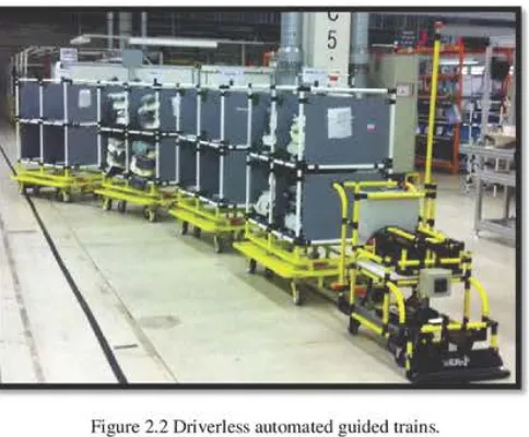
Driverless trains consist of a towing vehicle pulling one or more trailers to from trains(refer Figure 2.2). It was the first type of ACfiio be invented and it still widely used today. A common application is moving heavy payloads over long distance in
warehouse or factories with or without intermediate pickup and drop-off point along the path. For trains cw isting of five to ten trailers, this is an efficient transport system (Groover, 2008). Towing vehicles can pull a multitude of trailer types and have capag es ranging from 8,000 pounds to 60,000 pounds (Yaghoubi et.al. 2012).
The tugger, or tow-train AGV, has a design similar to standard tow tractors (Dziwis, 2005).
40
a
Figure 2.2 D1iverless automated guided trains.
(http://www.aziendainfiera.it/en/p/veicolo-guida-automatica-scaglia-indeva)
2.2.2
fltllet
Trucks
Automated g!lided pallet trucks, (Figure 2.3), are used to move palletized loads along
predetermined paths. [n the typica\ applications the vehicle is backed into the loaded
pallet by human worker who steer the truck and use its forks to elevate the load slightly.
[Then the worker drives the pallet truck to the guide pat1' and programs it is destination
and the vehicle proceed automatically to the destination for unloading. The capacity of
an AGV pallet truck ranges up to several thousand kilogram,
fJd
some trucks arecapable of handling two pallets rather than one (Groover, 2008). Designed to transport
palletized loads to and
tam
floor level, eliminating the need for fixed load stands(Yaghoubi et. al. 2012). Conventional forked vehicles have standard fork truck masts
(hydraulic or ball-screw) and forks integrated into their design. The interface between