University of Southern Queensland Faculty of Engineering and Surveying
Mobile Robot Guidance and Navigation
A dissertation submitted by
Leslie Airs
In fulfilment of the requirements of
Course ENG4111 and ENG4112 Research Project
Towards the Degree of
Bachelor of Engineering (Control and
Instrumentation)
Abstract
Autonomous robotic vehicle navigation relies on the vehicle being able to know where it is to an adequate degree of accuracy, and also to be able to sense the environment around it as required.
The purpose of this project, Mobile Robot Guidance and Navigation, is to design and construct hardware to interface sensors to the steering system of a mobile (wheel or track articulated) robotic vehicle.
Lab commissioning and field trials have shown the vehicle to be able to navigate over rough terrain while maintaining directional control.
Electronic compass resolution is 0.1 degrees, and maintains good stability when it is mounted clear of interfering devices when kept horizontal or error correction implemented.
University of Southern Queensland
Faculty of Engineering and Surveying
ENG4111 & ENG4112
Research Project
Limitations of Use
The Council of the University of Southern Queensland, its Faculty of Engineering and Surveying, and the staff of the University of Southern Queensland, do not accept any responsibility for the truth, accuracy or completeness of material contained within or associated with this dissertation.
Persons using all or any part of this material do so at their own risk, and not at the risk of the Council of the University of Southern Queensland, its Faculty of Engineering and Surveying or the staff of the University of Southern Queensland.
This dissertation reports an educational exercise and has no purpose or validity beyond this exercise. The sole purpose of the course pair entitled "Research Project" is to contribute to the overall education within the student’s chosen degree program. This document, the associated hardware, software, drawings, and other material set out in the associated appendices should not be used for any other purpose: if they are so used, it is entirely at the risk of the user.
Prof G Baker Dean
Certification
I certify the ideas, designs and experimental work, results analyses and conclusions set out in the dissertation are entirely of my own effort, except where otherwise indicated and acknowledged.
I further certify that the work is original and has not been previously submitted for assessment in any other course or institution, except where specifically stated.
Leslie Heath Airs
Student Number: Q9423076
Signature
Acknowledgments
I would like to thank my Family for their help, encouragement and patience.
Thanks to Dr. John Billingsley at USQ for an endless supply of ideas and advice as my project supervisor.
Thanks also to my colleague Howard Williams, who provided invaluable assistance with the rear drive design and production.
I’d also like to express my gratitude to Tarong Energy, in their support throughout my Engineering Degree studies.
Les Airs
lesairs@hotmail.com
Table of contents
Abstract ...2
Disclaimer ...3
Certification...5
Acknowledgments...6
Table of contents ...7
List of Figures ...8
Chapter 1 - Introduction ...10
Background ...11
Project Objectives ...13
Project Goals ...14
Implications and Effects...15
Chapter 2 – Guidance Systems ...18
Literature Review and Technical Survey...19
The Earth’s Magnetic Field...19
Electronic Compasses ...22
Errors and Performance of Electronic Compasses...29
Error Correction Techniques for Electronic digital compass...32
Evaluation of Alternative Solution...33
Research Summary...34
Chapter 3 - Implementation ...36
Selection of Compass Module to evaluate ...37
Design Constraints and Feasibility ...41
Proposed Design ...42
Hardware and Sub-system Design ...43
Test plan and performance criteria...49
Response of electronic compass – results ...50
Robot testing plan and performance criteria ...53
Health, Safety, Environmental, Sustainability and Ethical Considerations ...54
Sustainability...57
Mechanical Design...58
Electrical Design ...61
Software Design ...63
Commissioning ...65
Chapter 4 – System Analysis ...71
Field Trials ...72
Improvements resulting from field trial ...74
Chapter 5 - Future Work ...76
Chapter 6 – Summary...80
Appendix A – Project Specification...82
Appendix B – Software Listing...84
List of Figures
Figure 1 – The JPL / NASA Mars rover Spirit, artist’s impression (source: http://www.nasa.gov/vision/universe/solarsystem/30dec_gusevcrater.html)
...15
Figure 2 – Illustration of the earth's magnetic field ...21
Figure 3 – Single Axis Fluxgate (source: http://beale.best.vwh.net/measure/fluxgate/) ...22
Figure 4 – The ‘Mini Rover 7’ Miller, J 2004, ‘Mini Rover 7’, Circuit Cellar Magazine, Issue 165 April 2004, pp. 14-22 ...24
Figure 5 - Magnemometer sensor output vs angle; linear and x-y plots.‘Figure 2’ of Miller, J 2004, ‘Mini Rover 7’, Circuit Cellar Magazine, Issue 165 April 2004, pp. 15...25
Figure 6 - Magnetic distortion effects. From ‘Figure 3’ of Miller, J 2004, ‘Mini Rover 7’, Circuit Cellar Magazine, Issue 165 April 2004, pp. 18 ...25
Figure 7 - An illustration of the effects of ‘soft iron’ distortion on the earth’s magnetic field; From ‘Figure 4’ of Miller, J 2004, ‘Mini Rover 7’, Circuit Cellar Magazine, Issue 165 April 2004, pp. 18...25
Figure 8 - Practical experimental results from a compass guided robot travelling in a straight line. From ‘Figure 7’ of Miller, J 2004, ‘Mini Rover 7’, Circuit Cellar Magazine, Issue 165 April 2004, pp. 22...26
Figure 9 - The COMPASS hardware. From compass_ds.pdf, Omnitech Robotics 2000, pp2...27
Figure 10 - The VNU Hardware. From Point Research, 2004, brochure, viewed 30/05/05, <http://www.pointresearch.com/vnu_sheet.htm>...28
Figure 11 - The VNU CPU. From Point Research, 2004, brochure, viewed 30/05/05, <http://www.pointresearch.com/vnu_sheet.htm>...28
Figure 12 – Vector representation of earth’s magnetic field. From Phillips application noteAN00022 “Electronic Compass Design using KMZ51 and KMZ52” ...29
Figure 13 – Tilt error for electronic compass at S26.54 E151.84 Elevation 454m ...30
Figure 14 – mini gyroscope as used in hobby model aeroplanes http://www.minihobby.com/electronics/pgyro.jpg ...33
Figure 15 - The V2Xe compass module by PNI Corp. ...37
Figure 16 - The Devantech CMPS03 module ...38
Figure 17 - The Dinsmore 1625 sensor...38
Figure 18 - The TCM 2.5 Compass Module by PNI Corp. ...39
Figure 19 - Fluxgate magnetometer, manufactured by KVH. ...39
Figure 20 – PICAXE pinouts (source: www.picaxe.co.uk) ...43
Figure 21 – CMPS03 by Devantech ...44
Figure 22 – The Garden Cart Packaging...45
Figure 23 - The ‘electric bicycle’ motor to be used in the project ...45
Figure 24 - The ‘windscreen wiper’ steering actuator to be used in the project..46
Figure 25 - An example H-Bridge design (http://www.mskennedy.com/media/documents/4226rb.pdf)...47
Figure 27 - The robot control on breadboard. CMPS03 on right interfaces to a PC
through a PICAXE controller...49
Figure 28 – outdoor 15 minute test ...50
Figure 29 – Outdoor static test set-up ...50
Figure 30 – Outdoor 2 second test ...51
Figure 31 – Indoor 30 minute test ...51
Figure 32 – Cart rear axle before modification...58
Figure 33 – Cart rear drive after modification ...59
Figure 34- Steering mechanism after modifications ...60
Figure 35 – Robot electrical schematic ...62
Figure 36 – Cascaded control loop as implemented in software ...63
Figure 37 – MD22 I2C control registers (Source: www.robotparts.com.au) ...64
Figure 38 – Static steering test ...65
Figure 39 – The 850mm PVC mast to hold compass clear of interference. ...66
Figure 40 – Static steering test with compass on 850mm PVC mast...67
Figure 41 – Steering commissioning – steering actuator uncoupled ...68
Figure 42 - Steering closed loop test...69
Figure 43 –Steering closed loop test with ramping setpoint ...69
Figure 44 – First field trial results...73
Figure 45 – Placing of MOSFETs onto heavy duty heatsink...74
Background
Autonomous robotic vehicle navigation relies on the vehicle being able to know where it is to an adequate degree of accuracy, and also to be able to sense the environment around it as required.
The purpose of this project, Mobile Robot Guidance and Navigation, is to design and construct hardware to interface sensors to the steering system of a mobile (wheel or track articulated) robotic vehicle. This is presently the subject of an on-going research project involving the guidance and navigation of a model ‘load-haul dump truck’ at USQ based on ‘peer differential’ GPS. A brief assessment by myself, and input from Anders Loof (research student) of the performance of the present controls on this model truck suggest some shortcomings, namely;
1. GPS position updates are one second ‘old’ by the time they are delivered to the navigation algorithm.
2. Odometry in rough terrain or loose soil will always have errors substantial enough to produce an overshooting response or a path representing a zigzag when being updated at one second intervals via GPS.
As this project is being developed mostly off-campus, the first problem will not be addressed due to the need for USQ’s hardware to be off site for a considerable period. However, the second point above could be addressed by implementation of a high-speed directional control loop within the overall GPS control. This could enable high speed directional corrections within the GPS update period, keeping the vehicle on the heading setpoint despite odometry ‘slip’ and step changes due to rough terrain.
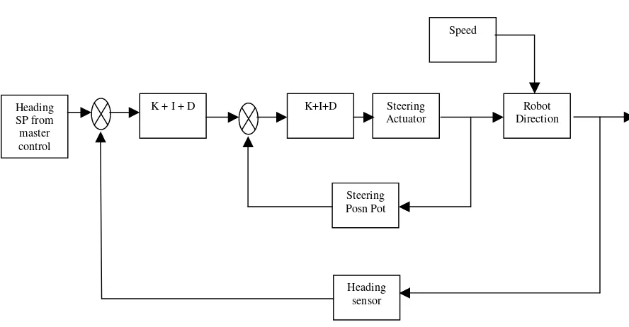
vehicle on track within tolerance. It would then receive periodic heading updates from a GPS ‘master’ control, to maintain absolute position control.
[image:12.595.112.556.190.421.2]Such a control system would look like:
Figure 1 –Control loop for heading control
Suitable heading sensors may be electronic or solid-state compass, gyroscopes, machine vision ‘vanishing point’ recognition, radar, sonar, the integral of an accelerometer, etc.
The research will focus on electronic compass for this application with some of the other sensors considered. The electronic compass promises to provide a reliable heading control with adequate resolution have a realistic development time for this project and be constructed and tested at a reasonable price.
Heading SP from master control
Robot Direction
K + I + D Steering
Actuator K+I+D
Steering Posn Pot
Heading sensor
Project Objectives
The overall objective of this project is to implement an effective electronic compass guidance system in hardware form, and demonstrate its functionality. Specifically, this should provide a robust high speed control loop that will provide good directional control within the sub-second timeframe, operable in a rural environment.
Further work may then be done to place a ‘correction layer’ above this control based on peer-differential GPS, and then place a ‘control layer’ over this to provide navigation for the system.
Project Goals
The following goals will enable the Objective to be reached:
1. Define performance criteria to be able to conclude the ‘objective’ has been met.
2. Research previous implementations of electronic compass control and the problems and advantages of this form of control.
3. Assess the options for directional control and produce outline design of the system to be implemented.
4. Carry out experimental evaluation of the chosen system and assess it against requirements of (1)
5. Implement the directional control system in hardware form and again assess its performance via field trials.
Performance criteria will be based on realistic outcomes from the research. These criteria will then develop into a test plan to test against the criteria. This will be defined in the ‘Implementation’ chapter of this document.
As time permits, the following may be also investigated:
1. Research suitable radio telemetry systems with the aim of making the peer-differential GPS system at USQ ‘wireless’.
Implications and Effects
Many people in many fields of study have been and are currently researching various autonomous navigation systems and tracking/location systems for mobile wheel or track type robots / vehicles. This is due to the benefits of such systems to aid human activities and needs. Uses are many and varied, some present uses are:
1. The military using unmanned vehicles to preserve human life, and also to improve the effectiveness of various war machines, such as the unmanned surveillance aircraft, which may stay in the air until refuelling is required. 2. Agriculture for the improvement of planting efficiencies and on large
properties for border and watering trough surveillance.
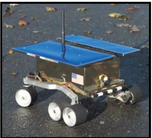
3. Scientific research where the areas to be studied are remote (eg Mars, see the picture of the Mars rover below) or very dangerous (eg active volcano craters).
4. Emergency services where tasks are dangerous such as bomb disposal or nuclear reactor inspections, or for tracking locations of vehicles in areas where GPS coverage is poor.
[image:15.595.157.463.488.721.2]The last two examples above still tend to rely very much on human ‘remote control’ rather than autonomous intelligent navigation.
Figure 2 – The JPL / NASA Mars rover Spirit, artist’s impression (source:
Some future uses of such guidance and navigation technology may be:
1. In passenger vehicles to allow an ‘autopilot’ mode, reducing accidents due to driver fatigue.
2. Automated mail/parcel/package delivery. 3. Factory parts delivery to work centres.
4. Geriatric care, enabling older citizens to travel despite reduced mobility, prolonging their self sufficiency.
Imagine ordering your shopping online, and then within an hour your order arrives at your door, delivered by an unmanned vehicle. Imagine a city where all deliveries are carried by small efficient unmanned vehicles, reducing pollution and improving efficiency. These are some benefits this technology may bring.
This technology may be seen by some to be ‘giving up control of the machines’ or in some ways reckless. But then autopilot systems in aircraft have been around since 1945 ( http://www.honeywell.com/sites/aero/Our_History.htm), and it is readily accepted that a Boeing 747-400 with 400 passengers on board will be on autopilot for a large proportion of any international flight.
This raises some ethical questions:
1. How far should a designer go to implement systems to ensure the vehicle does not harm people or place people at risk? To produce a ‘risk-free’ system, safety systems with redundant sub-systems, intelligent sensors, and other fail safe systems are required. This could be a very costly process. Through risk assessments would provide the solution to this question.
2. If a manned vehicle is involved in an accident, generally a human driver will take the ‘blame’, with little or no controversy. If a similar injury to a human is caused by an unmanned vehicle, who is to ‘blame’? The owner of the vehicle? The manufacturer? The Engineers? The OEM equipment supplier? Perhaps all parties would share some blame. It would be certain though, that unlike a human ‘mistake’, doubt would fall upon all other unmanned vehicles in operation as well. This situation must be avoided at all costs if the technology is to move forward.
Literature Review and Technical Survey
The Literature review will encompass the following points:
1. Is the earth’s magnetic field suitable for mobile robot guidance and navigation?
2. What errors and performance can be expected from electronic compasses?
3. Research of previous implementations of electronic compass control and the problems and advantages of this form of control (including error correction).
4. Research the control theory required to achieve stable control using multiple inputs into a single output system. (Kalman filter)
The Earth’s Magnetic Field
Electronic compasses rely on the earth’s magnetic field for their operation, so it is important to assess the suitability of both the electronic compass and the earth’s magnetic field in relation to the application of mobile robot guidance and navigation.
The earth’s magnetic field has been a navigation tool since the 13th century when the ‘Mariner’s Compass’ was used at times when the North Star was obscured. Early users of compasses were untrusting of them, as there was always an error between true and magnetic north. As time passed, this attribute of the earth’s magnetic field was studied, compass corrections were documented and then the perception of the compass changed to that of an important navigation tool (The
History of Navigation 2000, viewed 22/10/2005
When lava erupts from volcanos and hardens, it leaves evidence of the earth’s magnetic polarity. Geologic studies of this have shown that the earth’s magnetic field reverses direction on average every 200,000 years. However, the last time the earth’s magnetic field reversed was 780,000 years ago. Studies have also shown that the earth’s magnetic field has weakened by 10 percent since magnetic field strength records first begun in 1845. (Roach, The Earth’s Magnetic Field Is
Fading 2004, viewed 01/04/2005
<http://news.nationalgeographic.com/news/2004/09/0909_040909_earthmagfield .html>)
Modern studies of the earth’s magnetic field show that it is a dynamic system, known as Earth’s ‘geodynamo’. The slowly and constantly changing convection currents in the earth’s liquid core are thought to create the earth’s magnetic field.
The U.S. National Geophysical Data Centre maintains a 3-dimensional model of the earth’s magnetic field. This model can give accurate information about the present magnetic field parameters anywhere on or above earth, and can also give model-based predictions on the field parameters into the future. This model can be found at www.ndgc.noaa.gov. When the latitude, longitude, and elevation of my home address were entered into the U.S. National Geophysical Data Centre model, the following information about the magnetic field at my location was obtained:
Results for my back yard, date: 2005.7123 Declination = 10.556° changing by -0.003 °/year Inclination = -56.685° changing by 0.005 °/year X component = 28,612.6 changing by -11.47 nT/year Y component = 5,331.89 changing by -3.56 nT/year Z component = -44,282.4 changing by 26.57 nT/year
Horizontal Intensity = 29,105.15 changing by -11.93 nT/year Total Intensity = 52,990.95 changing by -28.75 nT/year
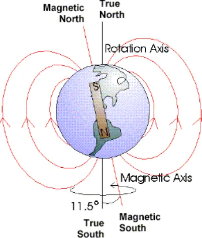
The next section on ‘electronic compasses’ explains how the declination of the earth’s magnetic flux lines affects the accuracy of electronic compasses when tilted. The figure below shows graphically that the flux lines only run tangent to the earth’s surface at (approximately) the equator. At any other point, the tilt error of the compass will need to be taken into account.
Figure 3 – Illustration of the earth's magnetic field
Electronic Compasses
Electronic Compasses simply detect the earth’s magnetic field in either two-axes or three-axes and compute from the relative magnitudes the present heading.
The sensors used in commercial electronic compasses are:
[image:22.595.224.387.318.494.2]• Fluxgate sensors – These are have a drive coil and sense coil. The drive coil current used to saturate the core in one direction is compared to that in another direction. The difference is due to an external magnetic field (http://beale.best.vwh.net/measure/fluxgate/)
Figure 4 – Single Axis Fluxgate (source: http://beale.best.vwh.net/measure/fluxgate/)
• Magneto-resistive. These consist of a magnet with a wire would around it. A constant current is passed through this wire. As the magnetic field changes (either because of proximity to other metallic objects, or the change in the earth’s magnetic field), the impedance of the coil of wire changes. (http://everything2.com/index.pl?node_id=569396)
• Magneto-inductive. This is a system patented by PNI corp. These change inductance as the magnetic field changes.
Electronic compasses can output heading and magnetic field information in various formats. This output can be as simple as the analog representation of field strength of the sensor on each axis as an output voltage, or as advanced as a digital calibrated high-resolution output on a serial bus such as the inter integrated circuit bus or I2C bus. Most electronic compasses have several outputs or several output modes to give the end-user a choice as to the format they receive the data in.
Choosing the format of the electronic compass output is important if error correction is to be used. For example, a digital value corresponding to heading may be convenient, but contains no information about field strength that may be used for error detection and correction.
Implementations of electronic compass control
[image:24.595.182.437.169.400.2]The Mini Rover 7
Figure 5 – The ‘Mini Rover 7’ Miller, J 2004, ‘Mini Rover 7’, Circuit Cellar Magazine,
Issue 165 April 2004, pp. 14-22
In the article by Joseph Miller describing his model based on NASA’s Mars rover, (Miller, J 2004, ‘Mini Rover 7’, Circuit Cellar Magazine, Issue 165 April 2004, pp. 14-22) the implementation of dead reckoning navigation utilising an electronic compass is discussed. Dead Reckoning (DR) is described as a mathematical method of tracking your present location by measuring speed (or distance) and the direction travelled at regular intervals, and computing a present location from this information. For the Mini Rover 7, Miller uses the PNI V2Xe electronic compass utilising magneto-inductive sensors to determine his robot’s heading (see notes on the V2Xe compass in the ‘Selection of Compass Module’ section of this document).
Figure 6 - Magnemometer sensor output vs angle; linear and x-y plots.‘Figure 2’ of Miller, J 2004, ‘Mini Rover 7’, Circuit Cellar Magazine, Issue 165 April 2004, pp. 15
Figure 7 - Magnetic distortion effects. From ‘Figure 3’ of Miller, J 2004, ‘Mini Rover 7’, Circuit Cellar Magazine, Issue 165 April 2004, pp. 18
Figure 8 - An illustration of the effects of ‘soft iron’ distortion on the earth’s magnetic field; From ‘Figure 4’ of Miller, J 2004, ‘Mini Rover 7’, Circuit Cellar
Figure 9 - Practical experimental results from a compass guided robot travelling in a straight line. From ‘Figure 7’ of Miller, J 2004, ‘Mini Rover 7’, Circuit
Cellar Magazine, Issue 165 April 2004, pp. 22
Figure 7 of Miller above, shows the feedback from an electronic compass on board a robot travelling in a straight line down the corridor of the authors home. At around the 100 inches mark, the robot passes the kitchen and the rear of a refrigerator. The heading veers off course at this point, while the magnitude of the magnetic field increases dramatically. Thus the departure of the magnitude of the magnetic field from a ‘normal’ value may be a good indicator of the quality of the heading information received.
Miller then repeats his experiments in an outdoor environment and does not find any of the magnetic disturbances as above. This is promising for the rural application of this research project. Miller does not provide any data on outdoor experiments, so this is one area where I will have to do my own investigations.
Compact Outdoor Multipurpose Pose Assessment System (COMPASS)
Figure 10 - The COMPASS hardware. From compass_ds.pdf, Omnitech Robotics 2000, pp2
Vehicle Navigation Unit (VNU)
Figure 11 - The VNU Hardware. From Point Research, 2004, brochure, viewed 30/05/05, <http://www.pointresearch.com/vnu_sheet.htm>
[image:28.595.215.404.359.583.2]Errors and Performance of Electronic Compasses
Electronic compasses can experience errors other than the ‘hard iron’ and ‘soft iron’ interference detailed by Miller above. Two-axis compasses by their nature will produce an error if the compass is not pointing directly to magnetic north and the compass is tilted.
The following diagram explains the reason behind this.
Figure 13 – Vector representation of earth’s magnetic field. From Phillips application noteAN00022 “Electronic Compass Design using KMZ51 and
KMZ52”
This tilt error can be expressed as (Stork, Thomas 2000, Electronic Compass Design using KMZ51 and KMZ52, Phillips Semiconductor, Germany):
)
sin
.
arctan(tan
cos
.
sin
.
sin
.
arctan
max max west east west eastHe
He
− −=
=
τ
δ
ε
δ
τ
δ
ε
The above equation for error was plotted against magnetic field data from the U.S. National Geophysical Data Centre for S 26.53905, E151.84723, Elevation 454m (my home address). The only data required to plot the expected error due to tilt is the angle of inclination as per the equation above.
[image:30.595.125.516.373.607.2]A plot of the error vs. tilt follows:
Figure 14 – Tilt error for electronic compass at S26.54 E151.84 Elevation 454m
The above chart indicates that for small amounts of tilt (less than 20 degrees) the error is roughly linear at 1.5 degrees error for every degree of tilt. Thus it is concluded that tilt of the 2-axis compass can produce very major heading errors.
Tilt error for electronic compass at S26.53905 E151.84723 Elevation 454m
-60 -50 -40 -30 -20 -10 0
0 20 40 60 80 100 120
Tilt angle (degrees)
E rr o r ( D eg rees)
If the amount of tilt is known accurately, the formula:
)
sin
.
arctan(tan
max
=
δ
τ
east−westε
Can be used to ‘compensate’ the tilt error, thus providing an effective method of tilt compensation. This could be as simple as a damped pendulum with position feedback to indicate the angle of departure from the horizontal.
Error Correction Techniques for Electronic digital compass
Magnitude of magnetic field
This technique as noted in Miller, is implemented by monitoring the magnetic field strength from the electronic compass. The earth’s magnetic field strength will be constant relative to the geographical location, and will not vary by a large degree as the compass moves. Magnetic interference, either by ‘hard iron’ sources (such as electric motors, radio transmitters etc), or soft iron sources (steel sheds, large ferrous objects), will show up by an increase or decrease in magnetic field strength. This deviation from normal field strength can then be interpreted as cause of a possible error and the heading data from the compass can then be regarded as ‘suspect’.
The Kalman Filter
Evaluation of Alternative Solution
Mechanical Gyroscopes are an alternative heading sensor. They are simply based around a spinning wheel mounted in a gimbal mount. To achieve high accuracy they require precision machining and high-quality components. This can make their purchase price well in excess of $10,000 US. Price alone makes this type of gyro unsuitable for this project.
Other less expensive Gyros are available, such as fibre-optic, and other low-cost mechanical gyroscopes, priced as low as $150US. These low cost gyroscopes are also low precision, with drifts in the order of tens of degrees per minute, making them too imprecise for this project.
Optical gyros in IC packaging are also under development, but won’t be considered for this project.
Research Summary
The Literature Reviews undertaken displayed a common theme; electronic compasses are widely used as part of heading control systems that also incorporate GPS and odometry to provide position information. This information is often combined by the use of the Kalman Filter to produce the best possible estimation given the types of errors associated with electronic compasses, GPS and dead reckoning.
The strengths of using the electronic compass in the dead reckoning loop are: • Accumulated heading drift is minimised, compared with using steering
position sensors.
• Heading errors created by rough terrain can be corrected immediately, without waiting for the next GPS position update.
• Where steering sensors cannot detect heading error due to rough terrain, the electronic compass is able to detect the heading change.
Weaknesses of using electronic compass in the dead reckoning loop are:
• Compass tilt can significantly affect the compass reported heading. A two-axis compass must be kept horizontal at all times for correct heading to be obtained. This can be done by gimbal mounting the compass. 3-axis compasses are able to automatically compensate for the tilt of the compass module.
other error correction methods such as magnetic field strength tracking would be required.
Selection of Compass Module to evaluate
There are several electronic compass variants that are suitable:
V2Xe by PNI (Vector 2X(e)) 1. 2-axis unit
2. resolution of 0.01 degrees
3. supply current of < 2mA @ 3VDC
4. Magneto-Inductive (MI) sensors (By PNI)
5. Heading Accuracy of 2 degrees (calibration required)
6. Motorola SPI protocol output for serial connection to host processor 7. Price $75 US (approx $100 AU)
Source: https://www.pnicorp.com/productDetail?nodeId=c39b
Figure 16 - The V2Xe compass module by PNI Corp.
Devantech CMPS03 - Philips KMZ51 magnetic field sensor, 1. 2-axis unit
2. resolution of 0.1 degrees
5. Heading Accuracy of 3 degrees (calibration required) 6. I2C and PWM outputs
7. Price 22.12 GBP or $85 AU
Source: http://www.robot-electronics.co.uk/shop/Compass_CMPS032004.htm
Figure 17 - The Devantech CMPS03 module
Dinsmore 1625 1. 2-axis unit
2. analog output on both axis (requires decoding for heading) 3. supply current of 19mA @ 5VDC
4. Hall Effect sensor to detect rotation of compass needle (mechanical field sensor)
5. Price approx $35 US ($46 AU)
Source: http://www.dinsmoresensors.com/1655spec.htm
TCM2 by PNI
1. A 3-axis tilt compensated unit (‘electronic gambling’) 2. Resolution 0.1 degree
3. Output is RS232C or NMEA0183 4. Input 5VDC @ 20mA
5. Magneto-Inductive (MI) sensors (By PNI) 6. Accuracy of 0.8 degree
7. Price: $719.00 US (approx $954 AU)
Source: https://www.pnicorp.com/productDetail?nodeId=cTCM2.5
Figure 19 - The TCM 2.5 Compass Module by PNI Corp.
Of the above listed contenders to be used in the trial, the Devantech CMPS03 utilising the Philips KMZ51 magnetic field sensor has been chosen because:
• Purchase price is relatively low ($85 AU)
• It has I2C outputs which interface directly to the PICAXE microcontroller which is to be used in the project
• Durable surface mounted component construction • Output resolution of 0.1 degree
Design Constraints and Feasibility
As stated in the opening comments, the overall objective of this project is to
implement an effective electronic compass guidance system in hardware form, and demonstrate its functionality. Specifically, this should provide a robust high speed control loop that will provide good directional control within the sub-second timeframe, operable in a rural environment.
This has to be achieved to a budget set by myself, and be able to be constructed using standard workshop tools and facilities that are available to me at my workplace (the Tarong Power Station).
Proposed Design
Requirements
A summary of the information gained has been assembled to create requirements for the
design of a test robot.
• Compass control must provide high speed corrections to steering actuator
• Simulations to be carried out to test design of hardware and software • Performance of the system must be measurable (ie. the ‘states’ of the
system must be logged for performance assessment)
• Test base (vehicle) must be robust to test in an outdoor ‘rural’
environment
Sub-system Requirements
The following sub systems will need to be assembled before field tests of the robot are able to proceed:
• Steering angle closed loop control (including steering actuator and steering position feedback).
• Motor speed control (Pulse Width Modulated control is the preference) • Compass unit
• Control unit to set speed, direction and provide close-loop control of the required steering angle to achieve the correct heading.
• Power distribution and control (including 12V battery, charging,
Hardware and Sub-system Design
Controller
• The PICAXE ‘flash’ memory based microcontroller has been chosen because its’ low cost and basic programming language should guarantee ease of use. The model microcontroller I am using is based upon a Microchip PIC16F873A microcontroller with the PICAXE ‘bootstrap’ program loaded. This enables the microcontroller to be programmed direct from a PC serial port. The assembler program for PC is available free from the PICAXE website, www.picaxe.co.uk. The PICAXE also implements I2C communications with other devices easily. This feature will be exploited to make design and construction faster and easier than using ‘traditional’ IC and device interfacing methods.
Electronic Compass
• Compass Board by Devantech CMPS03; see section on selection of compass module for details.
Figure 22 – CMPS03 by Devantech
Odometry
• Not to be implemented for the ‘heading control’ trial. May be implemented at a later date using optical encoders (such as those from a computer ‘ball type’ mouse)
Hardware platform
Figure 23 – The Garden Cart Packaging
Drive Motor
• 250W ‘Electric Bicycle’ motor – chosen because of ready mounted drive sprocket, fully enclosed motor / gearbox providing ruggedness, and sufficient output power.
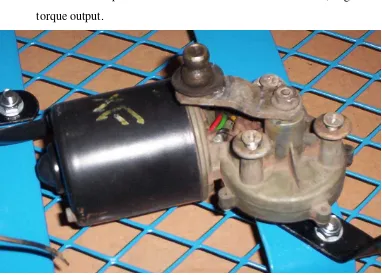
[image:45.595.194.459.498.746.2]Steering Servo
• Windscreen wiper motor – chosen due to fast slew rate, high torque output.
Figure 25 - The ‘windscreen wiper’ steering actuator to be used in the project
Power Supply
[image:46.595.149.531.126.401.2]Power Electronics
A suitable H-bridge design was investigated. Power (high current) MOSFET’s are required as the power handling part of the H-bridge to enable it to carry the full-load current of up to 15 amps DC at 12 volts, and to have the ability of pulse width modulation of the output for speed control of the drive motors.
[image:47.595.112.434.380.615.2]The original design idea was to use the microcontroller output pins to select the forwards and the reverse mode of the H-Bridge, and then have this signal ‘chopped’ using external logic and the PICAXE microcontroller’s Pulse output pins. The H-bridge would then only require some interfacing logic, providing the MOSFET drive signals and the interlocking function, ensuring that two MOSFET’s on the same ‘leg’ of the H-Bridge do not energise at the same time, causing a short circuit across the 12V supply.
Figure 26 - An example H-Bridge design
(http://www.mskennedy.com/media/documents/4226rb.pdf)
heatsinking, the continuous current draw can be increased to the MOSFET’s maximum continuous rating of 27 amps.
Figure 27 - The MD22 by Devantech
After assessing the time and cost involved in manufacturing the H-Bridge circuit from discrete parts, it was decided that the $160 purchase price of the MD22 was justified, because of its suitability for this project and the simplicity of connection to the PICAXE microcontroller via the I2C bus.
Human Interface
The initial consideration of the human interface proposed the following: • LCD display for useful information and setting during testing • Keyboard / pot for setting entry
• Serial to PC for detailed setting / data retrieval
Test plan and performance criteria
Outdoor response of electronic compass test plan
This is a series of experiments to determine the response of the compass module in an outdoor environment. Tests will include:
• Static drift test (accuracy and heading change over time)
• Step response test • ‘Slew’ rate test
Test ‘pass’ criteria will be:
• Drift of less than 0.4 degrees per minute
• Noise of less than 0.2 degrees between any two consecutive heading samples
• Slew rate of at least 90 degrees per second
[image:49.595.114.564.494.703.2]A test circuit was built based on the Devantech CMPS03. This test circuit is pictured below.
Response of electronic compass – results
The compass was tested in an outdoor location, and in an indoor location to compare results.
Stationary over 15 minutes outdoors
400 402 404 406 408 410 412 414 416 418 420 422 424 1 8 6 7 1 7 3 3 2 5 9 9 3 4 6 5 4 3 3 1 5 1 9 7 6 0 6 3 6 9 2 9 7 7 9 5 8 6 6 1 9 5 2 7 1 0 3 9 3 1 1 2 5 9 1 2 1 2 5 1 2 9 9 1 1 3 8 5 7 1 4 7 2 3 1 5 5 8 9 1 6 4 5 5 1 7 3 2 1 1 8 1 8 7 1 9 0 5 3 1 9 9 1 9 2 0 7 8 5 2 1 6 5 1 2 2 5 1 7 2 3 3 8 3 2 4 2 4 9 2 5 1 1 5 2 5 9 8 1 2 6 8 4 7 2 7 7 1 3 2 8 5 7 9 2 9 4 4 5 3 0 3 1 1 3 1 1 7 7 Sample No. H e a d in g -4 -3 -2 -1 0 1 2 3 4 5 6 7 8 S te p E rr o r
[image:50.595.123.503.186.431.2]Heading Step error
Figure 29 – outdoor 15 minute test
The outdoors test confirmed that some noise existed in the long term, and that the difference between consecutive readings (‘step error’ on the chart) was on average just larger than 0.1 degree, but regularly up to 0.2 of a degree.
[image:50.595.157.462.503.730.2]Static outdoor test - 2 seconds 400 402 404 406 408 410 412 414 416 418 420 422 424
1 3 5 7 9
1 1 1 3 1 5 1 7 1 9 2 1 2 3 2 5 2 7 2 9 3 1 3 3 3 5 3 7 3 9 4 1 4 3 4 5 4 7 4 9 5 1 5 3 5 5 5 7 5 9 6 1 6 3 6 5 6 7 6 9 sample number H e a d in g * 1 0 ( d e g re e s ) -4 -2 0 2 4 6 8 S te p E rr o r * 1 0 ( d e g re e s )
[image:51.595.123.501.115.367.2]Heading Step error
Figure 31 – Outdoor 2 second test
The same results over 2 seconds show a maximum error of 0.2 degrees and a maximum step between samples of 0.2 degrees. This indicates that some filtering or error correction may be required.
Stationary test over 30 mins in office environment
10 10.5 11 11.5 12 12.5 13 13.5 14 14.5 15
1 1301 2601 3901 5201 6501 7801 9101 10401 11701 13001 14301 15601 16901 18201 19501 20801 22101 23401 24701
sample no d e g re e s Series1
Figure 32 – Indoor 30 minute test
[image:51.595.126.521.456.667.2]within 50 metres of 275kV power distribution lines. The ‘noise’ exhibited in this office environment is typically 0.4 degrees (pk-pk).
The above step response test was carried out by manually rotating the compass approximately 90 degrees by hand, as fast as possible. The sample rate was 66 samples per second, thus the above 90 degree step was sensed by the compass in approximately 1/3 of a second. This may be the speed of the physical movement, but it does demonstrate that the slew rate must be better than 90 degrees per second as specified in the test criteria.
Manual 90 degree rotation for step response
0 200 400 600 800 1000 1200 1400 1600
1 3 5 7 9
1 1 1 3 1 5 1 7 1 9 2 1 2 3 2 5 2 7 2 9 3 1 3 3 3 5 3 7 3 9 4 1 4 3 4 5 4 7 4 9 5 1 5 3 5 5 5 7
sample number (66 samples / second)
Robot testing plan and performance criteria
The ‘test plan’ is:
• Assess each subsystem is functioning correctly via simulating an input signal and measuring the output.
• The closed loop steering / heading control will be tested without the drive motor operational to check the whole guidance system functionality.
• The robot will be given the task of maintaining a heading over a length of 20 to 50 metres on a variety of surfaces. Data logging and visual measurements will be made to determine the success or otherwise of the control system.
Acceptance Criteria
Health, Safety, Environmental, Sustainability and Ethical
Considerations
Risk Assessments
Under the broad heading of ‘constructing a robot’ come many steps and sub systems that pose a risk to health, safety and the environment.
Power sources – Lead Acid Batteries
Lead-acid batteries (car batteries) are designed to provide a high energy, low impedance power source suitable for starting a car. They are chosen for this project because of their low cost, high energy storage suitable for the 250W drive motor and steering actuator.
Lead – acid batteries produce hydrogen during charging and discharging. Their low impedance also delivers very high fault currents, capable of starting a fire, causing the battery to explode and potentially injuring humans nearby. The following risk assessment summarises these risks and explains how the risks are minimised.
‘Breakdown Event’
Likelihood of ‘breakdown’ occurring Consequences of ‘breakdown’ Risk Rating before controls
Controls to be implemented
Risk Rating After Controls
Explosion of hydrogen gas
Low – H2 concentration must be at combustion levels
High – acid released, energy released
Medium Battery to be situated in a vented box away from switching contacts and electronic devices. Battery charging to take place in well ventilated area only.
Insignificant
Battery short circuit
Medium – with fairly complex power
distribution, and power electronic switching, short circuits may occur
High – potential for fire, battery explosion
High Cabling to be large enough to carry maximum robot demand only to limit fault currents. Fuse or fusible link to be at battery terminal. Power distribution and power electronics to be designed to be fail-safe (ie. not causing a short circuit).
Construction
Construction involves the modification of the metallic structure of the ‘garden cart’, involving welding, drilling, grinding, painting and lathe use. Construction of the electronic sub-systems will involve soldering and drilling operations. The risks associated with these activities and their control methods are summarised below.
Welding
‘Breakdown Event’
Likelihood of ‘breakdown’ occurring Consequences of ‘breakdown’ Risk Rating before controls
Controls to be implemented
Risk Rating After Controls
Burns from hot weld splatter
High – electric arc welding produces hot sprays of ‘slag’
Medium – small and possibly deep burns to skin may result
Medium Flame-retardant welding suit to be worn while welding and face shield to be serviceable and worn correctly.
Low
Fire from hot weld
Low –
combustible materials need to be nearby
Medium –
potential for fire outbreak
Medium Combustible materials to be removed from area before welding.
Low
Burns to skin and eyes from high intensity UV source
Medium- welding ‘flash’ to eyes can happen if face mask is not correctly in position
High – long term vision impairment if ‘flash’ is severe
High Approved face mask in good condition to be worn correctly and tinted shields to be down at all times electrode is near the work piece. Long sleeved flame retardant shirt and long trousers to be worn.
Low
Drilling
‘Breakdown Event’
Likelihood of ‘breakdown’ occurring Consequences of ‘breakdown’ Risk Rating before controls
Controls to be implemented
Risk Rating After Controls
Burns from hot weld splatter
High – electric arc welding produces hot sprays of ‘slag’
Medium – small and possibly deep burns to skin may result
Medium Flame-retardant welding suit to be worn while welding and face shield to be serviceable and worn correctly.
Low
Fire from hot weld
Low –
combustible materials need to be nearby
Medium –
potential for fire outbreak
Medium Combustible materials to be removed from area before welding.
Low
Burns to skin and eyes from high intensity UV source
Medium- welding ‘flash’ to eyes can happen if face mask is not correctly in position
High – long term vision impairment if ‘flash’ is severe
High Approved face mask in good condition to be worn correctly and tinted shields to be down at all times electrode is near the work piece. Long sleeved flame retardant shirt and long trousers to be worn.
Grinding
‘Breakdown Event’
Likelihood of ‘breakdown’ occurring Consequences of ‘breakdown’ Risk Rating before controls
Controls to be implemented
Risk Rating After Controls
Burns from hot metal sparks
Low – sparks cool quickly
Medium – small burns to skin may result
Medium Ensure operator not standing in the path of sparks discharged from grinder. Ensure others cannot stray into the path of sparks.
Low
Fire from hot metal sparks
Low –
combustible materials need to be nearby
Medium –
potential for fire outbreak
Medium Combustible materials to be removed from area before grinding.
Low
Abrasive wheel shattering
Low – abrasive wheels are designed to resist shattering.
High – high speed impact of abrasive wheels can cause severe injuries
Medium Approved face shield in good condition to be worn correctly. Long sleeved flame retardant shirt and long trousers to be worn.
Inspect wheel for structural integrity before grinding. If abrasive wheel appears ‘jammed’ with material (ie. aluminium) replace the wheel before starting.
Low
Painting
‘Breakdown Event’
Likelihood of ‘breakdown’ occurring Consequences of ‘breakdown’ Risk Rating before controls
Controls to be implemented
Risk Rating After Controls
Inhalation of fumes
Medium Medium – short term dizziness may occur. Long term effects have been documented
Medium Use spray paint in open, well ventilated location, preferably where a gentle breeze is present. Wear a P2 organic filter mask while spraying.
Low
Pint spray in eyes Medium High – painful eye injury may occur
Medium Wear goggles, keep face well away from work, if there is a breeze, stay up wind of work area.
Low
Lathe Use
‘Breakdown Event’
Likelihood of ‘breakdown’ occurring Consequences of ‘breakdown’ Risk Rating before controls
Controls to be implemented
Risk Rating After Controls
Metal / Nylon pieces shearing from work piece embedding in eye
Medium – a lot of high velocity material leaves work piece during lathe operation
High – potential for permanent eye injury
Medium Wear goggles, keep face away from work piece, ensure correct turning technique is being used.
Low
Clothing caught in rotating machinery
High – operations to be carried out in winter when lots of clothing is worn
High – permanent damage to limbs
High Ensure sleeves are rolled up securely, and all other clothing is secured, jewellery removed. Maintain clearance around rotating work piece and chuck at all times.
Soldering
‘Breakdown Event’
Likelihood of ‘breakdown’ occurring Consequences of ‘breakdown’ Risk Rating before controls
Controls to be implemented
Risk Rating After Controls
Inhaling burning flux fumes
High – fumes are released for every solder joint, and face is usually above PCB being soldered.
Low – long term effects may occur
Medium Keep face away from work piece when soldering. Use an extraction fan to remove soldering flux fumes.
Low
Burns from soldering iron
Low Medium – deep
burn to skin is possible
Medium Return soldering iron to holder after each soldering operation. Switch soldering iron off after use.
Low
Eye damage from component lead trimming
Medium –
component lead trimming generally results in component leads leaving the PCB at high velocity
Medium – eye injury
Medium When trimming leads, point the work piece away from yourself and others, usually down, or secure the component lead with pliers in one hand while trimming with the cutters in the other hand.
Low
Testing
‘Breakdown Event’
Likelihood of ‘breakdown’ occurring Consequences of ‘breakdown’ Risk Rating before controls
Controls to be implemented Risk Rating After Controls ‘Runaway’ vehicle
Medium Medium – may cause damage to people or property
Medium Vehicle speed to be mechanically limited through high gear ratios.
Test area to be chosen away from roads and populated areas. Emergency stop button on top of robot.
Bumpers wired to stop the robot if contact is made with an object.
Low
Muscle strain from lifting robot
High – robot will be heavy due to construction and power source.
Medium – back / muscle strain.
Medium Robot to be transported using low loading trailer. Robot to be lifted using two people. If robot is heavier than 40kg, then ramps for the trailer will be required for robot to ‘drive’ up.
Low
Sustainability
Mechanical Design
The objectives of the mechanical design are to provide a robust base capable of travel over ‘rough’ terrain to enable the testing of the vehicle in a rural environment. The chosen platform was a ‘garden cart’ kit utilising pneumatic wheels and ‘car like’ steering.
Drive Design
[image:58.595.125.494.322.627.2]Drive design and construction was a major part of the mechanical construction, as the entire rear axle had to be rebuilt around a drive shaft mounted on transmission bearings.
Figure 33 – Cart rear axle before modification
The production of the rear drive shaft design involved the following steps: • Removal of the ‘standard’ garden cart axle and supports
• Production of a bracket suitable to hold the 250W drive motor
• The drive shaft had to be turned down in a lathe to enable it to fit into the ‘transmission’ bearings.
• The bearings in the rear wheels had to be removed, and solid nylon blocks were manufactured to take the place of the bearings
• A drive sprocket with correct tooth pitch and 27 teeth was purchased. This gave a chain drive reduction of 3:1. The tooth width was too wide however for the drive chain matching the motor output sprocket, so the drive shaft sprocket had to be machined to reduce its width. The centre of the sprocket was also bored out to the drive shaft diameter; two and locking grub screws were installed at 90 degrees to hold the drive sprocket in place.
[image:59.595.113.514.383.684.2]• Locking pin holes were drilled through the wheel hub, nylon block and drive shaft to enable locking pins to be installed, preventing slip between the drive shaft and the wheel hubs.
Steering Design
The steering design requires an actuator to be attached to the steering mechanism of the garden cart to enable actuation of the front wheels.
The steps in this implementation were:
• Tighten standard steering system using ball joints. The existing steering had over three degrees of movement between each wheel, which was unacceptable for this project. Removing the standard connecting rod and installing a connecting rod with ball joints on each end rectified this. This reduced movement between each steering wheel forward angle to an undetectable level.
• Build bracket for mounting of windscreen wiper motor onto the front steering support. This bracket was manufactured from 5mm thick steel plate, drilled to accommodate the actuators output shaft bearing housing, and with mounting holes matching the actuators existing 6mm mounting screw holes.
• Ball joints and 6mm threaded rod connect the actuator output shaft to the midpoint of the steering arm, maintaining steering geometry (thus keeping a 1:1 ratio between actuator angle and steering angle throughout the steering range)
• Mount position feedback components. A basic 10k linear potentiometer was mounted on the steering support. An arm was manufactured out of 5mm aluminium plate to enable connection of ball joint rod to the feedback pot. The other end of the feedback connection rod connects to the steering arm, maintaining a 1:1 ratio throughout the steering range.
Electrical Design
The Electrical design had to incorporate the high power H-Bridge drive requirements as well as regulated 5VDC for the microcontroller, compass module and the logic on board the H-Bridge drive module. This was provided from a 17AHr 12V sealed lead acid battery, with power distributed from a fuse block. The supply went direct to the H-Bridge power MOSFET’s via 1.5mm2 cable and a 15 Amp fuse. The 5V logic supply is provided via a 78L05 voltage regulator and filtering capacitors to filter the switching noise from the H-bridge circuit.
A laptop PC is carried on the robot for use as a data logger. The PICAXE microcontroller outputs serial data each processing cycle for the data logger to read via the serial port. This information is then imported to a spreadsheet for performance analysis and graphing (see commissioning and field trials for examples)
Software Design
The software for the robot implements two cascaded control loops and sequencing for the robot test headings.
[image:63.595.113.559.283.510.2]The robot heading control was implemented through the following control loop, with the heading setpoint provided from a sequence of setpoints, changing at a fixed time.
Figure 37 – Cascaded control loop as implemented in software
The microcontroller is to also control the I2C drive motor interface to control the robot’s forward and reverse velocity.
Heading SP
Robot Direction
K Steering
Actuator K+D
Steering Posn Pot
Compass
Register
Address Name Read/Write Description
0 Mode R/W Mode of operation (see below)
1 Speed1 R/W Left motor speed (mode 0,1) or speed (mode 2,3)
2 Speed2/Turn R/W Right motor speed (mode 0,1) or turn (mode 2,3)
3 Acceleration R/W Acceleration for i2c (mode 0,1)
4 Unused Read only Read as zero
5 Unused Read only Read as zero
6 Unused Read only Read as zero
[image:64.595.165.454.90.329.2]7 Software Revision Read only Software Revision Number
Figure 38 – MD22 I2C control registers (Source: www.robotparts.com.au)
The software was coded into the PICAXE microcontroller using PICAXE Programming Editor 4.1.9, programming using BASIC language as it applies to the PICAXE 28X microcontroller.
PICAXE microcontrollers do not implement floating-point variables. This presented a problem with error calculations when the control loop was being implemented in software, there being no expressions for negative numbers. This problem was addressed by creating a test to see if the error was positive or negative, then branching the program so the error and control block implementations could be handled with positive numbers.
Another problem that had to be avoided with the microcontroller programming was register overflow. This is where a value of greater than 256 is entered into a register. The result of this is simply a loss of the MSB, eg. 257 will be read back as 1. This situation can easily occur in control loops where a calculation like “b2 = error * gain” if the error is large. To prevent this problem, the error value was limited to 256/gain. This enabled full controllability around the setpoint, while preventing overflow of the register.
Commissioning
Data logging was the first system to be commissioned. A steering setpoint of 128 (1/2 travel, or straight ahead) was programmed in to the microcontroller, the drive motor was disabled and the system was started with the data logging PC running. Six straight traces on the chart was the expected result. The actual result showed a large amount of activity:
Static Steering Test / Compass Interference Test
0 50 100 150 200 250 300 350 400 450 500 1 1 6 3 1 4 6 6 1 7 6 9 1 1 0 6 1 2 1 1 3 6 1 5 1 1 6 6 1 8 1 1 9 6 2 1 1 2 2 6 2 4 1 2 5 6 2 7 1 2 8 6 3 0 1 3 1 6 3 3 1 3 4 6 3 6 1 3 7 6 3 9 1 4 0 6 4 2 1 4 3 6 4 5 1 4 6 6 4 8 1 4 9 6 5 1 1 5 2 6 5 4 1 5 5 6 5 7 1 5 8 6 6 0 1 6 1 6 6 3 1 6 4 6 6 6 1 sample v a lu e
[image:65.595.122.565.294.538.2]heading feedback setpoint abs error drive motor variable gain*error
Figure 39 – Static steering test
Analysis of this test revealed some ‘noise’ on the steering feedback input without any actual steering mechanism movement. It was found the magnitude of this ‘noise’ was up to 2 on the 0 to 256 analog input. This was causing the steering actuator to be energised to attempt to reposition the steering.
analog input to smooth this noise. A low pass point of 30Hz was decided upon, which is ½ the estimated sample rate of the microcontroller.
[image:66.595.251.370.318.708.2]A side effect noticed during this test is that although the robot was stationary, the ‘heading’ value was changing regularly by up to 10 degrees (the heading value is expressed on a scale of 0 to 3600 being 0 to 360 degrees). These heading spikes correlate directly with the steering drive motor variable, and hence the energisation of the motor. For the compass control to be effective this interference had to be eliminated. Increasing the distance between the motors and the compass was attempted with the installation of an 850mm high PVC mounting mast and the results noted.
The chart of results of the test with the compass mounted on the mast and with the 30Hz low-pass-filter on the steering input:
Static Steering Test / Compass Interference Test - Compass on Mast
0 100 200 300 400 500 600
1 9 17 25 33 41 49 57 65 73 81 89 97
1 0 5 1 1 3 1 2 1 1 2 9 1 3 7 1 4 5 1 5 3 1 6 1 1 6 9 1 7 7 1 8 5 1 9 3 2 0 1 2 0 9 2 1 7 2 2 5 2 3 3 2 4 1 2 4 9 2 5 7 2 6 5 2 7 3 2 8 1 2 8 9 2 9 7 3 0 5 3 1 3 3 2 1 3 2 9 3 3 7 Sample V a lu e
[image:67.595.120.539.148.359.2]heading feedback setpoint abs error drive motor variable gain*error
Figure 41 – Static steering test with compass on 850mm PVC mast
The ‘noise’ on the steering feedback was manually induced to promote steering actuator movement to assess the level of interference of the compass on the 850mm high mast. An assessment of the numerical results shows ‘ambient’ noise of the compass in my workshop as +/- 0.2 degrees, whit no correlation between the motor energising and the heading error. Thus, the mounting of the compass on a mast and the addition of the low pass filter to the steering input was successful.
Steering Loop Commissioning
Steering System Comissioning - Steering Uncoupled 0 50 100 150 200 250 300
1 17 33 49 65 81 97
1 1 3 1 2 9 1 4 5 1 6 1 1 7 7 1 9 3 2 0 9 2 2 5 2 4 1 2 5 7 2 7 3 2 8 9 3 0 5 3 2 1 3 3 7 3 5 3 3 6 9 3 8 5 4 0 1 4 1 7 4 3 3 4 4 9 4 6 5 4 8 1 4 9 7 5 1 3 5 2 9 5 4 5 5 6 1 5 7 7 5 9 3 6 0 9 6 2 5 sample no v a lu e
[image:68.595.121.545.102.335.2]feedback setpoint abs error drive motor variable gain*error
Figure 42 – Steering commissioning – steering actuator uncoupled
The actual steering position was manually varied from the setpoint, and the steering actuator direction noted to ensure it was driving in the correct direction to correct the error. The output to the I2C H-Bridge was going from full forward (255) to full reverse (0). After these parameters were checked, the link from steering to actuator was installed to close the loop.
Closed Loop Steering Test 0 20 40 60 80 100 120 140 160 180 200
1 2 3 4 5 6 7 8 9 10 11 12 13 14 15 16 17 18 19
sample
v
a
lu
e
[image:69.595.119.514.101.315.2]feedback setpoint abs error drive motor variable gain*error
Figure 43 - Steering closed loop test
The friction of the wheels on the concrete surface provided dampening for the system. If the wheels are lifted above the surface, then an unstable response is obtained, as illustrated in the following commissioning exercise, where a triangle wave was used as the steering setpoint. A stable response was obtained when the wheels were in contact with the ground. On the 5th cycle, the wheels were lifted off the ground, and the result was instability, as can be seen below.
Ramp Setpoint Utilising PD Control
0 50 100 150 200 250
1 24 47 70 93
1 1 6 1 3 9 1 6 2 1 8 5 2 0 8 2 3 1 2 5 4 2 7 7 3 0 0 3 2 3 3 4 6 3 6 9 3 9 2 4 1 5 4 3 8 4 6 1 4 8 4 5 0 7 5 3 0 5 5 3 5 7 6 5 9 9 6 2 2 6 4 5 6 6 8 6 9 1 7 1 4 7 3 7 7 6 0 7 8 3 8 0 6 8 2 9 8 5 2 8 7 5 8 9 8 9 2 1 9 4 4 sample v a lu e
velerr feedback setpoint abs error drive motor variable gain*error
[image:69.595.118.534.499.725.2]An attempt to counter this instability was made by adding a ‘derivative’ negative feedback, simply by tracking the rate of change from one microcontroller cycle to the next. It can be seen in the chart above that the velocity error value is quite active, but ineffectual at preventing the oscillations when the wheels aren’t damped by the friction with ground.
It was decided at this point that because the steering wheels should always be in contact with a surface providing enough damping for stability, the instability issue with the steering control loop raised was not a real problem.
Commissioning of the drive motor was achieved by sending a drive signal to the I2C H-Bridge:
drivemotors:
i2cslave $B0,i2cfast,i2cbyte ' Define i2c slave address for the MD22
writei2c 1,(b8) 'steering motor speed / direction writei2c 2,(168) 'drive motor speed / direction
Field Trials
The aim of the first field trial was to assess: • mechanical construction
• power electronics
• directional control (outer compass control loop)