Design and Development of Planar Antenna for GSM Application
ABDULHADI HASAN ALJOUMAH
This report is submitted in partial fulfillment of requirements for the award of Bachelor Degree of Electronic Engineering (Wirelesscommunication Electronic
Engineering) with honours
Faculty of Electronic and Computer Engineering Universiti Teknikal Malaysia Melaka
“I hereby declare that this thesis entitled “Design And Development Of Planar Antenna For GSM Application” is a consequence of my own research idea concept for works that have been cited clearly in the references.”
Signature : …..……… Name : Abdulhadi Hasan Aljoumah
APPROVAL
“I, hereby declare that I have read this report and in my opinion, this report is sufficient in terms of scope and quality for the award of Bachelor of Electronic Engineering (Wireless Communication) with Honors.”
Signature : …..……… Supervisor’s Name : Dr. Imran Bin Mohd Ibrahim
ACKNOWLEDGEMENT
In the name of Allah, the most Beneficent, and the most Gracious. Praises be to Allah, for blessing and granting me with the strength and patience I needed to finally and successfully complete my Final Year Project. I would like to express my gratitude and special thanks to my supervisor Dr. IMRAN BIN MOHD IBRAHIM, who in spite of being extraordinarily busy with his duties, took time out to hear, guide and keep me on the correct path and allowing me to carry out my Final Year Project.
I would like to sincerely thank my family for always been there for me, thank you for encouraging me in all of my pursuits and inspiring me to follow my dreams. I am especially grateful to my parents, who supported me emotionally and financially. This journey would not have been possible without their support.
I would like to take the chance to thank all lecturers who taught me in the past four years and had a great contribution that qualify me to do my final year project. I would like to thank Dr. Kok Swee Leong, and lectures who arrange for INOTEK exhibition, for their efforts in providing information and cooperation to help students achieving the goals of final year projects. I would like to thank the technicians, Mr.Imran bin Mohamed Ali and Mr Mohd Sufian bin Abu Talib for their cooperation during fabrication and measurement processes.
ABSTRACT
ABSTRAK
TABLE OF CONTENTS
CHAPTER TITLE PAGE
ACKNOWLEDGEMENT i
ABSTRACT ii ABSTRAK iii TABLE OF CONTENTS iv
LIST OF TABLES vii
LIST OF FIGURES viii
1 INTRODUCTION 1
1.1Introduction 1
1.2 Problem statement 2
1.3Objectives 2
1.4Scope of project 3
2 LITERATURE REVIEW 4
2.1 Introduction 4
2.2 Critical Literature review 4
2.3 Summary 13
2.4 Antenna theory 14
2.5 Antenna properties 14
2.5.1 Impedance 15
2.5.2 Return Loss 15
2.5.4 Bandwidth 16
2.5.5Radiation Pattern 16
2.5.6 Gain 17
2.5.7 Polarization 17
2.6Circularly Polarized Microstrip Patch Antenna 21 2.7Introduction of Microstrip Antenna (MSA) 23
2.7.1 Metallic patch 23
2.7.2 Dielectric substrate 24
2.7.3 The ground 24
2.7.4 Feeding 25
2.7.4.2 Microstrip feeding 25
2.8 Conclusion 26
3 METHODOLOGY 27
3.1 Introduction 27
3.2 Flow Chart 28
3.3 Design Specification 29
4 RESULTS AND DISCUSSION 37
4.1 Introduction 37
4.2. Antenna Simulation Result 37
4.2.1 Return Loss 37
4.2.2 Gain 39
4.2.3 Radiation pattern and directivity 39 4.3 Measurement Result of the Antenna 40
4.3.1 Return loss 40
4.4 Filed Test 43
4.5 Conclusion 44
5 CONCLUSION AND RECOMMENDATION 45
5.1 Conclusion 45
5.2 Recommendation 46
REFERENCES 47
LIST OF TABLES
TABLE TITLE PAGE
3.1 FR4 substrate's properties 29
LIST OF FIGURES
FIGURE TITLE PAGE
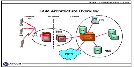
1.1 GSM structure 1
2.1 Return Loss 1800MHz of antenna 5
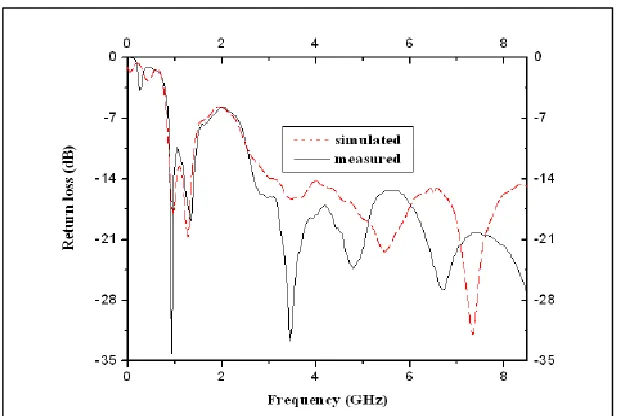
2.2 Measured return loss of proposed antenna compared to simulated result
6
2.3 Comparison of simulation and experimental VSWR results 7 2.4 Simulated and measured return loss for SPSTMA 8
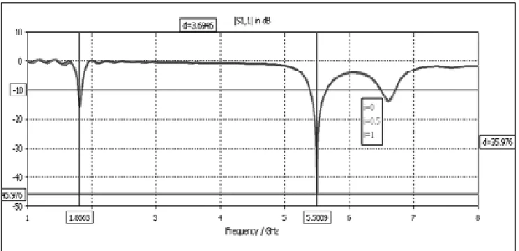
2.5 Simulated Return Loss Curve 9
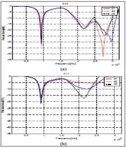
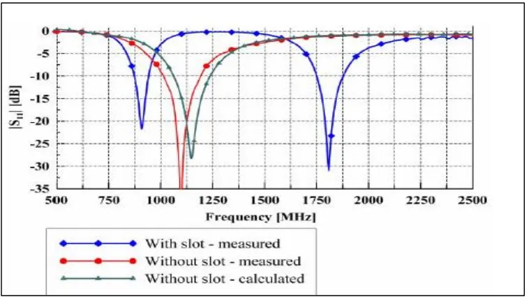
2.6 Comparisons of the simulated return loss for different distances 10 2.7 Calculated and measured magnitudes of the input reflection 11 2.8 Geometry and detailed dimensions of the proposed antenna
(Unit)
12
2.9 Radiation pattern of antenna[12] 17
2.10 Plane Wave and its Polarization Ellipse at Z=0[14] 19
2.11 Type of Polarization [14] 19
2.12 Linear Polarization [14] 20
2.13 Circular Polarization [14] 20
2.14 Elliptical polarization [12] 21
2.15 Basic Microstrip antenna[15] 23
2.16 Different shapes for microstrip antenna [15] 24
2.17 Coaxial feeding [16-15] 25
2.18 Direct Microstrip Feed Line 26
3.2 3D diminution of basic (PIFA) antenna 30
3.3 CST software 31
3.4 Simulated PIFA Antenna structure 32
3.5 Simulated PIFA Antenna with Front Side 32
3.6 Basic Equipment 33
3.7 Soldering 33
3.8 Dimensions’ Measurement 33
3.9 Completed Design 33
3.10 The Measurement of Return Loss 34
3.11 Radiation Pattern Measurement 34
3.12 Cable Loss Measurement 35
3.12 Received Power Measurement 35
4.1 Planar Inverted-F antenna (PIFA) Parametric Study of Patch Length
38
4.2 Return loss & Bandwidth for planar Inverted-F antenna (PIFA)antenna
38
4.3 3 The Realized Gain of planar Inverted-F antenna (PIFA)antenna
39
4.4 Radiation pattern in polar form of planar Inverted-F antenna 39 4.5 The directivity in 3D form of planar Inverted-F antenna
(PIFA)antenna
40
4.6 Measured Return loss of planar Inverted-F antenna (PIFA)antenna
41
4.7 Planar Inverted-F antenna (PIFA) Return Loss Comparison 41 4.8 Comparison between simulation and measurement of radiation
pattern
43
CHAPTER 1
INTRODUCTION
1.1 Introduction
[image:14.612.181.447.531.665.2]Wireless communication has become as one of the most famous and commonly used applications nowadays, such as personal communication services (PCS), cellular communications, satellite communications, broadcasting, High-Definition TV (HDTV), Personal Digital Assistant (PDA), wireless LAN, Bluetooth… etc. Global System for Mobile (GSM) is a second-generation cellular system standard. It's considered as the first cellular system which provides a specification for the digital modulation and network-level architecture and services. Radio Frequency (RF-ICS) for GSM standard started at 1900. GSM which was firstly introduced in Europe in 1991, is now considered as the most commonly used cellular standard. In addition, GSM is widely utilized in the world [1][2].
In the wireless communication systems, Antenna is considered as a significant part which plays an important role in GSM application [3]. However, there are many Types of an antenna which used for GSM application, since not all type of antenna can be used for mobile, the most popular antenna that can be used are the microstrip antenna and planar antenna due to their significant characteristic. This project will introduce a planar antenna which suits mobile phone with a set of specifications.
1.2 Problem statement
Nowadays, modem and future wireless systems are placing greater demands on antenna designs. The communication equipment requires small size antenna so the weight and size of this equipment would be decreased to improve the physical appearance. There are many types of the antenna but not all of them are capable of being used in a mobile phone for GSM application. Therefore, this project proposed a small size planar antenna design for GSM phone application which has the advantages of:
i. Providing a small antenna size which can be easily attached to mobile phones. ii. Maintaining the performance in term of (gain and return loss).
1.3 Objectives
The objectives of the project are:
i. To design planar antenna at operating frequency of 868 MHz for GSM application with bandwidth 800 to 900 MHz.
ii. To simulate and fabricate the planar antenna.
CHAPTER 2
LITERATURE REVIEW
2.1 Introduction
This chapter covers the background and the fundamentals of antenna parameters that affect the performance of the antenna in any wireless system. In addition, this chapter present the researched journals that were reviewed about antenna deigns to achieve our specification at frequency of 868 MHz. After going through the desired journals, a comparison was done to ensure the best method is selected to complete the project.
2.2 Critical Literature Review
The literature review was performed by referring to some journals to collect the related information and facts that can be used in the design process of this project. Prior to design process; research was carried out by performing a review of the literature in several journals related to research the topic of design and development of planar antenna for GSM application. In this part, firstly, every journal will be explained.
2.2.1 Planar Dipole Antenna Design at 1800mhz Band Using Different Feeding Methods for GSM Application
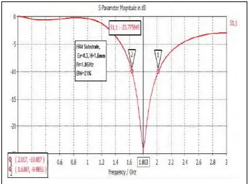
MHz. However, two types of feeding configuration have been used to feed the antenna in order to match 50-ohm transmission line, the via-hole integrated balun, and quarter wavelength open stub. As a result, the via-hole integrated balun shows maximum return loss of -25db and bandwidth can be improved up to 25% and 30%. VSWR of 1.116 v at a length of 59 mm and width 4 mm. While the quarter wavelength open stub provides max return loss of -47.88db with VSWR 1.008 << 2 and also shows a better radiation pattern. For implementation, the quarter wavelength open stub method is very convenient and suitable, since it does not require soldering through it and also has narrow bandwidth but again it depends on the application requirements [3][4] .
Figure 2.1 Return Loss 1800 MHz of antenna
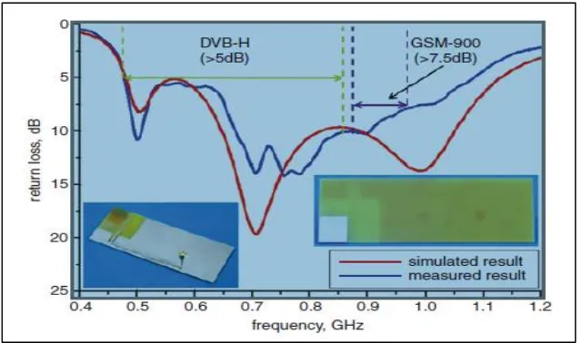
2.2.2 Broadband Planar Antenna Based On CRLH Structure for DVB-H and GSM- 900 Applications
addition, the broadband performance of the planar antenna has been demonstrated by simulation and experiment. Finally, the measured gain, efficiency, and radiation pattern meet the requirements for DVB-H and GSM-900 applications[5][6].
2.2.3 Band Miniaturized Microstrip Fractal Antenna for A Small GSM1800 + UMTS Mobile Handset
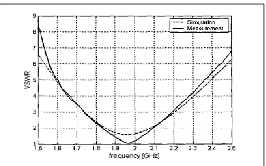
[image:19.612.154.474.154.343.2]In this paper, the author introduced a novel design of a fractal miniaturized mobile terminal antenna. A miniaturized fractal edge patch in a PIFA configuration has been used as a method to design the antenna. However, the patch element length reduced down to 0.17h, which is 38% of a common rectangular patch. In this design, the ground plane is used with a small handset size. In addition, this design meets the requirement of handset applications for mobile communications. As a result, the structure matched to 50 R, the size (1 0~4. 5c m) and radiation pattern with the low directivity. (VSWR 5 3) in the frequency range covering GSMl800 and UMTS operating bands. The results have matched and validated the requirement of the antenna design by following the procedure[7][8].
Figure 2.3 Comparison of simulation and experimental VSWR results
2.2.4 Planar Compact Bidirectional Dual Wide Band Antenna for GSM and UWB Communications
The study of this research proposed a planar compact bi-directional antenna configuration for dual wideband operation with a wide lower band and ultra-wide higher band. The technique used in this paper is integration technique. In addition, it shows a characteristic with significant compactness. however, this configuration has been analyzed using finite integration technique based on commercial software CST studio. An antenna is optimized for 865 MHz to 1.42 GHz lower operating band and 2.5 GHz to 20 GHz higher operating band. The frequency domain analysis provides a good study about different characteristics of the SPSTMA. As a result, it has been concluded that the shorting strip reduces the size of the antenna and can be used to tune the operating frequency band.
Figure 2.4 Simulated and measured return loss for SPSTMA
2.2.5 Dual Band Micros-Trip Patch Antenna for GSM And WiMAX Application
Figure 2.5 Simulated Return Loss Curve
2.2.6 Electrical Characteristics of a Dual-Band Micros-Trip Patch Antenna for GSM/ UMTS / WLAN Operations:
Figure 2.6 Comparisons of the simulated return loss for different distances
2.2.7 Dual-Band Micros-Trip Antenna for GSM Applications
bands using a single feed because of simplicity [15][16].
Figure 2.7Calculated and measured magnitudes of the input reflection Coefficient (S11) for the final antenna design
2.2.8 A Small Patch Antenna for GSM Applications