UNIVERSITI TEKNIKAL MALAYSIA MELAKA
SMART ANTI-THEFT SURVEILLANCE SYSTEM
This report is submitted in accordance with requirement of the Universiti Teknikal Malaysia Melaka (UTeM) for the Bachelor of Computer Engineering Technology
(Computer Systems) with Honours
by
MUHAMMAD HAFIZ BIN MOHD HASHIM B071310605
940228-14-6007
UNIVERSITI TEKNIKAL MALAYSIA MELAKA
BORANG PENGESAHAN STATUS LAPORAN PROJEK SARJANA MUDA
TAJUK: Smart Anti-Theft Surveillance System
SESI PENGAJIAN: 2016/17 Semester 1
Saya MUHAMMAD HAFIZ BIN MOHD HASHIM
mengaku membenarkan Laporan PSM ini disimpan di Perpustakaan Universiti Teknikal Malaysia Melaka (UTeM) dengan syarat-syarat kegunaan seperti berikut:
1. Laporan PSM adalah hak milik Universiti Teknikal Malaysia Melaka dan penulis. 2. Perpustakaan Universiti Teknikal Malaysia Melaka dibenarkan membuat salinan untuk
tujuan pengajian sahaja dengan izin penulis.
3. Perpustakaan dibenarkan membuat salinan laporan PSM ini sebagai bahan pertukaran antara institusi pengajian tinggi.
4. **Sila tandakan ( )
SULIT
TERHAD
TIDAK TERHAD
(Mengandungi maklumat yang berdarjah keselamatan atau kepentingan Malaysia sebagaimana yang termaktub dalam AKTA RAHSIA RASMI 1972)
(Mengandungi maklumat TERHAD yang telah ditentukan oleh organisasi/badan di mana penyelidikan dijalankan)
(TANDATANGAN PENULIS)
Alamat Tetap:
Lot 333, Km 4,
Kampung Bukit Badong,
45600 Bestari Jaya, Selangor, Malaysia
Disahkan oleh:
(TANDATANGAN PENYELIA)
Cop Rasmi:
iii
DECLARATION
I hereby, declared this report entitled ―Smart Anti-Theft Surveillance System‖ is the results of my own research except as cited in references.
Signature : ………
Name : ………
iv
APPROVAL
This report is submitted to the Faculty of Engineering Technology of UTeM as a partial fulfillment of the requirements for the degree Bachelor of Computer Engineering Technology (Computer Systems) with Honours. The member of the supervisory is as follow:
v
ABSTRACT
vi
ABSTRAK
vii
DEDICATIONS
Alhamdulillah, praise to the Almighty Allah S.W.T
This project is dedicated to:
My parents, My beloved family,
My Supervisor, My lecturers, And all my friends
viii
ACKNOWLEDGMENTS
I would like to express my gratitude towards the following groups of people
which not only given me continuous support and guidance throughout the entire
course of this project. First and foremost, I would like to thank and grateful to Allah
SWT for the great health and ability in completing this paper. I would like extent my
deepest appreciation to my beloved parents, Mr. Mohd Hashim Bin Effandi and
Madam Adawiah Binti Mohd Noor who always pray for my success in this research
study. To Mr. Aiman Zakwan Bin Jidin who is my supervisor who not only guided
me but also provided me the knowledge about coding, teach me how to use each of
software and experience that help in this research project. Next is my lecturer Mr.
Shamsul Fakhar who always become my source of reference. Besides that, my
fiancée Nur Hafizahanis Binti Marjumin who always give me spirit to complete this
project. Not forgotten to my best friend, Wong Shao Pei, Ashwadie and Ahmadee
who always teach and guide me in solving the problems happened during this study.
Last but not least, others staff and friends in Fakulti Teknologi Kejuruteraan, FTK
ix
TABLE OF CONTENTS
DECLARATION... iii
APPROVAL ... iv
DEDICATIONS ... vii
ACKNOWLEDGMENTS ... viii
TABLE OF CONTENTS ... ix
LIST OF TABLE ... xiv
LIST OF SYMBOLS AND ABBREVIATIONS ... xv
CHAPTER 1 ... 16
1.0 Introduction ... 16
1.1 Problem Statement ... 18
1.2 Objective ... 19
1.3 Work scope ... 19
1.4 Project Significance ... 21
1.5 Conclusion ... 22
CHAPTER 2 ... 24
2.0 Introduction ... 24
2.1 Motion Detection ... 24
2.2 Security System ... 25
2.2.1 Intrusion Detection System... 27
2.2.2 Types of Equipment and Protection ... 28
2.2.3 Motion Detection Devices ... 28
2.3 Related Research and Projects ... 32
2.3.1 Closed Circuit Television, CCTV ... 32
2.4 Hardware and Software ... 36
2.4.1 Camera ... 36
2.4.2 Arduino Microcontroller ... 39
2.4.3 GSM Technology ... 42
x
2.5 Programming Language and Environment ... 47
2.5.1 Arduino Programming Language ... 47
CHAPTER 3 ... 49
3.0 INTRODUCTION ... 49
3.1 PROJECT METHODOLOGY ... 51
3.2 Project Overview ... 53
3.2.1 Process Flowchart ... 54
3.3 Design and Preparation of the System ... 56
3.3.1 Material and Equipment ... 57
3.4 Budget and Costing ... 59
3.4.1 Direct Cost ... 59
CHAPTER 4 ... 60
4.0 Introduction ... 60
4.1 Project Hardware Layout ... 60
4.1.1 Schematic Layout ... 60
4.1.2 Component Layout ... 62
4.1.3 PIR and IR sensor Configuration ... 63
4.1.4 Configuration of Camera and SD Module ... 64
4.1.5 Configuration of GSM900A ... 65
4.1.6 Hardware setup... 65
... 66
4.2 Project Software Layout ... 68
4.2.1 Arduino Uno Code Development ... 68
4.3 Experimental Result ... 72
4.4 Project Analysis ... 74
4.4.1 PIR and IR Range Coverage ... 75
4.4.2 Power Limitations of Arduino Uno... 76
4.5 Discussion ... 77
4.6 Project Limitation ... 79
CHAPTER 5 ... 80
5.0 Introduction ... 80
5.1 Expecting Result ... 80
xi
xii
LIST OF FIGURES
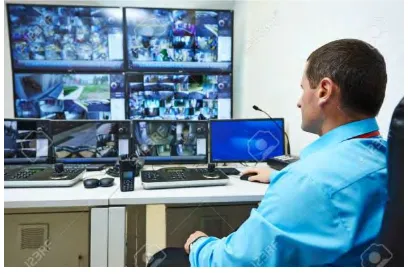
Figure 1.0 Security guard monitors the normal camera surveillance system ... 18
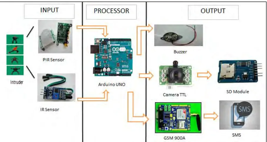
Figure 1.1: Block diagram based on camera surveillance system, GSM and buzzer ... 20
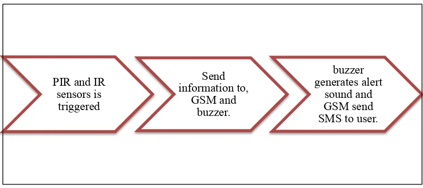
Figure 1.2: Block diagram for this project’s process ... 21
Figure 2.0: Basic Sonar detector ... 30
Figure 2.1:Motion Detector Ultrasonic ... 30
Figure 2.2: Microwave Detector ... 31
Figure 2.3: living thing object is being detect by PIR sensor ... 32
Figure 2.4: Normal surveillance system diagram ... 33
Figure 2.5: JPEG Color Camera UART-TTL Interface with Infrared ... 37
Figure 2.6: Inside webcams lens (at top) and image sensor (at bottom) ... 37
Figure 2.7: Arduino UNO microcontroller ... 39
Figure 2.8: Arduino Mega ... 40
Figure 2.9: GSM Module SIM900 (Shelby & Bormann, 2009) ... 43
Figure 2.10: Schematic of A GSM System (Halonen, et al., 2003) ... 43
Figure 2.11: Call Flow for SMS (Bodic, 2005) ... 45
Figure 3.0: Project’s flowchart ... 52
Figure 3.1: Architecture of project ... 53
Figure 3.2: Overall system block diagram Smart Anti-Theft Surveillance system ... 53
Figure 3.3: Process’ flowchart ... 55
Figure 4.0: Schematic diagram connection of sensors and buzzer with Arduino Uno ... 61
Figure 4.1: Schematic diagram connection between camera and Arduino Uno ... 61
Figure 4.2: component layout between sensors and buzzer with Arduino Uno ... 62
Figure 4.3: component layout between camera and Arduino Uno ... 62
Figure 4.4: Component layout between GSM900A and Arduino Uno ... 63
Figure 4.5: Component set up on breadboard ... 66
Figure 4.6: Component set up in black box (state in high light density) ... 67
Figure 4.7: Component set up in black box (state in low light density) ... 67
Figure 4.8: Arduino IDE ... 68
Figure 4.9: Coding of PIR and IR subject in both HIGH state ... 69
Figure 4.10: Result from sensors in serial monitor ... 69
xiii
Figure 4.12: Result of sending SMS in serial monitor ... 70
Figure 4.13: Coding for capture image function ... 71
Figure 4.14: Result of image’s data in hexadecimal in serial monitor ... 71
Figure 4.15: Components in black box casing ... 72
Figure 4.16: Image capture in high density of light ... 73
Figure 4.17: Image capture in low density of light ... 73
Figure 4.18: User gets notification through SMS ... 74
Figure 4.19: Distance at 2cm from the IR sensor ... 75
Figure 4.20: Distance at 3cm from the IR sensor ... 76
xiv
LIST OF TABLE
Table 2.0: Comparison motion detection tools ... 29
Table 2.1: Comparison between types of security camera ... 34
Table 2.2: Comparison between Arduino UNO and Arduino Mega ... 41
Table 2.3: External AT command ... 48
Table 3.0: List of material and equipment ... 57
Table 3.1: Cost material and equipment ... 59
Table 4.0: Connection between Arduino Uno and PIR sensor ... 63
Table 4.1: Connection between Arduino Uno and IR sensor ... 64
Table 4.2: Connection between Arduino Uno and TTL camera ... 64
Table 4.3: Connection between Arduino Uno and SD Module ... 64
Table 4.4: Connection between Arduino Uno and GSM900A ... 65
xv
LIST OF SYMBOLS AND ABBREVIATIONS
CCTV = Closed Circuit Television
HD = High Definition
GSM = Global System for Mobile
IDE = Integrated Development Environment
SMS = Simple Message System
IDS = Intrusion Detection System
Hz = Hertz
CMOS = Complementary metal-oxide
semiconductor
PC = Personal Computer
K = Kilo
Webcams = Web Camera
NKRA = National Key Right Action
I/O = Input and Output
B = Bytes
TDMA = Time Division Multiple Access
16
CHAPTER 1
INTRODUCTION
1.0 Introduction
As increasing economy growth of Malaysia but there is still also increasing the percentage of crime. This thing should not happen because when one country is stable in economy the crime rate should be low. Surprisingly, with the high technology nowadays CCTV for surveillance system there is still not a solid answer to fight the increasing crime rate. Camera that being used for surveillance system is comes with different quality of image and video that can be recorded. Even for high resolution 1080p or High Definition resolution camera intruder still can enter the restricted area.
This is happen because when the intruder or burglar enter a home when owner outside the house, usually they will wear mask to cover their face. The items or precious belonging still can be stolen during the CCTV is monitored and recording the crime action. This leads to a motivation to study and develop this project by improve and upgrade the normal surveillance security system to a smart anti-theft surveillance system by adding features like detect human body motion and trigger an alert after the intruder being detected.
17
detect the presence of criminal. By using simple sensors, it will be used to detect the presence of intruder. Once the sensors is in high state, the camera will take a snap of scene happened.
This project is able to make user save memory storage capacity for surveillance system. The system only snaps or takes picture when the crime is happened. The image taken will be saved in JPEG image format. For surveillance camera system, usually they will monitor and recorded scene then save it in hard disc. For 1080p resolution they will use 1Tb of memory capacity for one week and if nothing happen they will reset it back every 7 days. This leads to no recorded scene that are last longer more than 7 days. To overcome this storage issue, engineer all around the world try to make the recorded scene of surveillance camera system is stored in cloud. Contradiction for cloud storage is it may be stolen by third parties and it still gets a price tag for the service to store data in there.
Arduino GSM will acts as microcontroller application where it will receive the information from the program inside the camera that the presence of human motion is being detected. Next it will trigger alerts to the user by SMS and to the intruder by using buzzer. By this way, it will skip the part where a normal surveillance system relies on third party like security guards or the owner itself to trigger an alert. Imagine that one security guard need to monitor for 10 monitor display that show the video recording from 10 different CCTV for 8 hours in monitoring security room. This will lead to human error where the security guard will feel exhausted and did not realize that the intruder already enter the restricted area. Furthermore, for wireless CCTV application for home usage even the owner can monitor from outside the house but still it will has difficulty to monitor 24 hours.
18
intruder already enter the restricted area. Furthermore, for wireless CCTV application for home usage even the owner can monitor from outside the house but still it will has difficulty to monitor 24 hours.
This project will focus on how to study and developing the camera that can detect human body motion and trigger an alert. The review is on the smart anti-theft surveillance system based on the PIR sensor and IR sensor, Arduino Mega and GSM module. The real time system is a must for security system manner as a delay might not be forgiven because the criminal will have high chance to escape.
[image:18.612.243.447.287.424.2]
Figure 1.0 Security guard monitors the normal camera surveillance system
1.1 Problem Statement
For a growing economy country, a reliable monitoring security system is a must to protect their goods and assets from being harmed or stolen. Nowadays technology surveillance camera is only for monitoring and recording any activities that happen in the marked area. Hence, a surveillance system nowadays needs an improvement to make a safer environment for public or industry.
19
cannot help to solve unauthorized person that enter prohibited area to steal something because the surveillance system used just record and monitor.
Next problem is alert only can be triggered when third party (security guard or police) or user itself turn it on. This reaction even it is happen during crime scene but it is always too late as the criminal already escaped. The basic idea for improvement in this project is to detect the human movement and trigger an alert when an intruder enters into restricted area. After the camera can detect the intruder, the system inside will trigger an alert through Simple Message System, SMS. This will allow direct information of intruder to the user or owner of a building. Thus, the possibility of intruder case can be decrease.
1.2 Objective
There are only three objectives that are determined and needs to be achieved at the end of this project. The objectives of this project are as below.
1. To study on how to make a surveillance system camera that can detect
human-like motion and give alert to the user about intruder.
2. To develop an efficient Smart Anti-Theft Surveillance System security system that can detect a body motion and trigger an alert when an intruder enter restricted area.
3. To analyze the effectiveness between body motion detectable surveillance system and normal surveillance system.
1.3 Work scope
20
Furthermore, the work scope of this project also want to study the on how to develop a body motion camera that can help to improve surveillance system nowadays. This system will try to catch presence of the human body movement and it makes it as an input to trigger the alert. Hence, user will feel secured as it will notice when intruder trespass the restricted area.
This project can be divided into two main parts which is software and hardware development. In software part, it will focus more on create part in Arduino IDE which can control camera, sensors and coding for SMS. Second part is hardware part where after the camera receive input from human movement it will send a SMS to user by using GSM module by Arduino. Next is the hardware like buzzer will be turn on when it receive input from the sensors. Combination of PIR sensor and IR sensor with ability to detect human movement. User will receive alert from GSM by SMS after intruder(s) entered into restricted area. For testing part, this project will use two subjects as intruders that try to break into room in high intensity of light and low intensity of light. This difference environment is to show the ability of this project to be used in day and night. As to conclude this project will have these features:
[image:20.612.118.552.438.631.2]
Figure 1.1: Block diagram based on camera surveillance system, GSM and buzzer PIR and IR
21
Figure 1.2: Block diagram for this project‘s process
1.4 Project Significance
The significance and important of this project is to help public and industry to protect their valuable belongings. Every person has their own precious things to be protected. Based on chapter 6 in National Key Right Action, NKRA crime case involving robbery or stolen vehicle inside house area show 70% crime rate percentage from all crime case in Malaysia. Major case from 70% is house or building that is fully installed CCTV system. This leads to insecurity feeling in every Malaysian where there is still trustable answer to reduce this number of crime case. Main idea to do this project is from this report in chapter 6 in NKRA where improvement on normal camera surveillance system is a must to help public feel more secure. By study to improve this normal camera surveillance system to body motion detectable camera and in the same time trigger an alert which is more effective than just rely on third party like security guard. To make this project can be achieved to help public, the system must:
22
Snap only human body shape not animal shape.
Trigger an alert at location area to give warning to the intruder
Send an alert in email form to the user to inform the situation happen.
The trigger must be in real time.
In today nowadays where mobile phone have been upgrade to smartphone, 3G connection to 4G LTE and from normal television display into High Definition. Now it times for camera surveillance system to be upgrade to body motion detectable camera surveillance system in help public to protect their belongings. By this, public can go anywhere without need to be worried the precious belonging being stolen.
In term of researcher, it is hoped that this project will open the eyes to other inventors and researcher in the future to improve the security system that we have today. This will lead to a lot benefits as crime rates also can be reduced. This also as prove where science and technology can help public in fight the crime.
By completing this project, I hope that I can help industry and public in to protect their items by this smart anti-theft system. This system is more focus on how to detect the body motion then trigger an alert to the user. Hence, the user will keep updated about the security of their belonging even far from home.
1.5 Conclusion
23
24
CHAPTER 2
LITERATURE REVIEW
In this chapter, the theory will be discussed regarding this project, which reveals the knowledge that gained via resources from reference book, journal, articles, newspapers, and websites that contain application, research work, and related theories. Gain knowledge and study about the related theory of surveillance system, camera, PIR sensor, IR sensor, GSM, SMS, related search, programming language, people behavior, hardware requirement and existing technology.
2.0 Introduction
In this project, some studies and research information had been done in order to make the project become reality and successful. This study and research will focus more on some major aspect and component that related to the project. To make a great outcome every rational idea and theory being compared among it and the best will be chosen to be selected to be used in this project.
2.1 Motion Detection