UNIVERSITI TEKNIKAL MALAYSIA MELAKA
STUDY OF FLUID FLOW IN DIFFERENT FUEL RAIL USING
CFD SIMULATION
This report submitted in accordance with requirement of the Universiti Teknikal Malaysia Melaka (UTeM) for the Bachelor Degree of Mechanical Engineering
Technology (Automotive Technology) (Hons.)
by
MUHAMMAD RIZAN BIN MUSA B071310438
911209-12-5697
iii
DECLARATION
I hereby, declared this report entitled “Study of Fluid Flow in Different Fuel Rail using Computational Fluid Dynamics (CFD) Simulation” is the results of my own
research except as cited in references.
Signature :...
Name : Muhammad Rizan Bin Musa
iv
APPROVAL
This report is submitted to the Faculty of Engineering Technology of Universiti Teknikal Malaysia Melaka (UTeM) as a partial fulfilment of the requirements for the
Bachelor’s Degree in Mechanical Engineering Technology (Automotive Technology) with Honours. The member/person of the supervise is as follow:
...
(Project Supervisor)
v
ABSTRACT
vi
ABSTRAK
vii
DEDICATIONS
I would like to dedicate to my beloved parents, my supervisor (Ms Najiyah Safwa Binti Khashi’ie), my co-supervisor (Mr Mohd Suffian Bin Ab Razak) in guiding me
viii
ACKNOWLEDGMENTS
Firstly, I would like to take deepest appreciation to my supervisor, Ms Najiyah Safwa Binti Khashi’ie from Faculty of Engineering Technology, Universiti Teknikal Malaysia Melaka (UTeM) in guiding and supervise me while completing this project.
Then, to all my friends, thank you for supporting and helping me during this project research had make.
ix
TABLE OF CONTENT
DECLARATION ... iii
APPROVAL ...iv
ABSTRACT ... v
ABSTRAK ...vi
DEDICATIONS ... vii
ACKNOWLEDGMENTS ... viii
TABLE OF CONTENT ...ix
LIST OF FIGURES ... xiii
LIST OF TABLES ... xv
LIST OF ABBREVIATIONS, SYMBOLS AND NOMENCLATURE ... xvi
CHAPTER 1 ... 1
1.0 Introduction ... 1
1.1 Background of Study ... 1
1.2 Problem Statement ... 4
1.3 Project Objective ... 5
1.4 Scope of Project ... 6
CHAPTER 2 ... 7
2.0 Introduction ... 7
2.1 Engine Vehicle ... 7
x
2.2 Fuel Injection System ... 10
2.3 Fuel System ... 11
2.4 Fuel Rail ... 12
2.5 Fluid Flow ... 15
2.5.1 Turbulent and Laminar Flow... 15
2.5.2 Reynolds Number (Re) ... 16
2.5.3 The Navier-Stokes Equation ... 17
2.5.4 Viscosity... 18
2.5.5 K-epsilon (k-ε)... 18
2.6 Fluid Flow Properties ... 19
2.6.1 Head Losses... 19
2.6.2 Pressure Losses ... 20
2.7 Software ... 21
2.8 Computational Fluid Dynamics (CFD) ... 21
2.8.1 Function of CFD ... 23
CHAPTER 3 ... 25
3.0 Introduction ... 25
3.1 Computational Procedures ... 27
3.1.1 Computation Domain ... 27
3.1.2 Geometric Parameters and Boundary Conditions ... 28
3.2 Computer Aided Design (CAD) Model ... 28
xi
3.4 Apply Boundary Conditions... 35
3.5 Computational Analysis ... 35
3.6 Visualization ... 35
CHAPTER 4 ... 37
4.0 Introduction ... 37
4.1 Benchmark Results (Standard Fuel Rail) ... 37
4.1.1 Benchmark Model (SolidWorks) ... 37
4.1.2 Velocity ... 39
4.1.3 Pressure ... 41
4.2 Performance / Modified Fuel Rail Results ... 42
4.2.1 Velocity ... 43
4.2.2 Pressure ... 44
4.3 Comparison of Results ... 46
4.3.1 Velocity ... 46
4.3.2 Pressure ... 48
4.4 Conclusion of the Results... 49
CHAPTER 5 ... 51
5.0 Introduction ... 51
5.1 Conclusions ... 51
5.1.1 Results Summary ... 51
5.1.2 Achievement of Project Objectives ... 52
xii 5.2 Recommendations... 53
REFERENCES ... 54
xiii
LIST OF FIGURES
Figure 1.1: The General Fuel Rail System
(http://zilvia.net/f/showthread.php?t=549436). ... 2
Figure 1.2: The Bosch L-Jetronic system has been used on various Japanese, European and domestic vehicles (Bosch). ... 3
Figure 1.3: Fuel Rail System for In-line Five Engine (http://forums.quattroworld.com/s4s6/msgs/21108.phtml). ... 4
Figure 2.1: Four Stroke Combustion Engine Cycle. ... 8
Figure 2.2: Example for Standard Fuel Rail ...12
Figure 2.3: Examples for Performance Fuel Rails...13
Figure 2.4: Variety of Fuel Injection Fuel Rails (Delphi Multec). ...14
Figure 2.5: Boundary Layer Separations ...19
Figure 2.6: Example Real Experiment and CFD Simulation (Kuzmin, n.d.). ...22
Figure 2.7: Example of CFD Applications (Dr Kamarul Arifin, 2007)...23
Figure 2.8: Example of CFD Application (Dr Kamarul Arifin, 2007) ...24
Figure 2.9: CFD Process (Dr Kamarul Arifin, 2007) ...24
Figure 3.1: The Flow Chart of Methodology ...26
Figure 3.2: Dimension of Inner Fuel Rail. ...27
Figure 3.3: Hole Distance of Fuel Rail. ...27
Figure 3.4: First Step...28
Figure 3.5: Drawing Circle ...29
Figure 3.6: Pad Definition ...29
Figure 3.7: Draw Circle ...30
Figure 3.8: Pad Definition ...30
Figure 3.9: Draw Circle ...31
Figure 3.10: Pad Definition ...31
Figure 3.11: Draw Construction Line ...32
Figure 3.12: Draw Four Circle ...32
Figure 3.13: Pad Definition ...33
Figure 3.14: Hole of Fuel Rail ...33
Figure 3.15: Meshing using SolidWorks ...34
Figure 3.16: Boundary Conditions ...35
Figure 4.1: Standard Fuel Rail 4G13/15 Modelling ...38
xiv
Figure 4.3: Standard fuel rail 4G13/15 modelling in cross-section ...39
Figure 4.4: The flow in the fuel rail ...39
Figure 4.5: Standard fuel rail 4G13/15 (velocity) ...40
Figure 4.6: Flow trajectories of velocity in standard fuel rail ...40
Figure 4.7: Cut plot (contours) of velocity in standard fuel rail ...40
Figure 4.8: Standard Fuel Rail 4G13/15 (Pressure) ...41
Figure 4.9: Flow trajectories of pressure in standard fuel rail...41
Figure 4.10: Cut plot (contours) of pressure in standard fuel rail ...42
Figure 4.11: Performance Fuel Rail Modelling ...42
Figure 4.12: Performance Fuel Rail 4G13/15 (Velocity) ...43
Figure 4.13: Flow trajectories of velocity in performance fuel rail ...43
Figure 4.14: Cut plot (contours) of velocity in performance fuel rail ...44
Figure 4.15: Performance Fuel Rail 4G13/15 (Pressure) ...44
Figure 4.16: Flow trajectories of pressure in performance fuel rail ...45
Figure 4.17: Cut plot (contours) of pressure in performance fuel rail ...45
Figure 4.18: Point parameter of velocity in standard fuel rail...46
Figure 4.19: The graph of comparison velocity of standard and performance fuel rail ...47
Figure 4.20: Point parameter of pressure in standard fuel rail ...48
xv
LIST OF TABLES
Table 2.1: The complete working cycle of the four stroke engine (Robert Bosch,
2006). ... 8
Table 2.2: The Ranges of Reynolds Number (Walski, 2001) ...17
Table 3.1: Common Liquids ...28
Table 4.1: Comparison velocity between standard and performance fuel rail ...47
Table 4.2: Comparison pressure between standard and performance fuel rail ...48
xvi
LIST OF ABBREVIATIONS, SYMBOLS AND
NOMENCLATURE
CAD - Computer Aided Design
CATIA - Computer Aided Three-Dimensional Interactive Application CFD - Computational Fluid Dynamics
K - K-epsilon
K - Kelvin
m - metre
mm - millimetre
m/s - metre per second
Re - Reynold Number
SA - Sparlart-allmaras
SST - shear stress transport
Pa - Pascal
- shear stress
- absolute (dynamic) viscosity
dy
dV - time rate of strain
f - Darcy friction factor
1
CHAPTER 1
INTRODUCTION
1.0 Introduction
Chapter 1 is the framework of this project that including brief introduction about the Electronic Fuel Injection (EFI), fuel rail, objective and scope of this project.
1.1 Background of Study
The Electronic Fuel Injection (EFI) has applied to automobiles in mass production use was first introduced in the late 1960s. This is a system for introducing fuel into internal combustion engines and into automotive engines in particular. On diesel engines, fuel injection is a necessity, whilst on petrol engines fuel injection is an alternative to the carburetor. Most of the spark ignition internal combustion engines operate with a stoichiometric air petrol ratio since it enables the catalyst to control emissions level (Chalet & Chesse, 2016). They is differences between carburetor and fuel injection. The primary difference is that fuel injection atomizes the fuel through a small nozzle under high pressure, while a carburetor relies on suction created by intake air accelerated through a venturi tube to draw the fuel into the airstream.
2 called Extra High Pressure Injection (XPI) and is a so called Common Rail (CR) system developed by Cummins and Scania (Engineering, 2011).
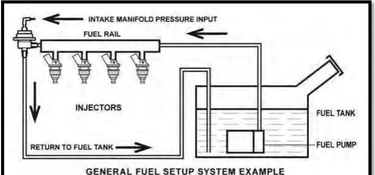
[image:17.595.147.516.299.471.2]According to (Injectors, n.d.), the nominal injection pressure for most Ford vehicles that used EFI system is 39.15psi (270kPa). Most vehicles today use one injector per cylinder. When the solenoid is energized, fuel sprays out into the valve port. Fuel is delivered to the injector by a high pressure electric pump at around 40 psi. Fuel delivery is controlled by the injectors which are cycled by the computer. The computer produces a signal to open the injectors for a certain length of time depending on engine conditions relayed by sensors. The more fuel is injected, the longer that the injector is open.
Figure 1.1: The General Fuel Rail System (http://zilvia.net/f/showthread.php?t=549436).
3 Figure 1.2: The Bosch L-Jetronic system has been used on various Japanese,
European and domestic vehicles (Bosch).
4 Figure 1.3: Fuel Rail System for In-line Five Engine
(http://forums.quattroworld.com/s4s6/msgs/21108.phtml).
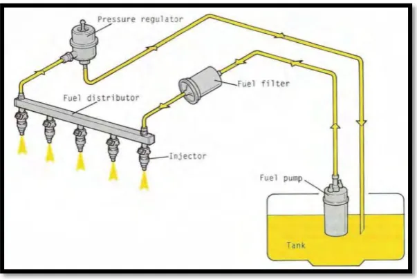
The fuel rail is essentially a tubular fuel manifold designed to carry fuel to the injectors as well as hold them in place on the intake manifold. Along to the electric fuel pump, fuel filter, injection valves, and pressure regulator, the fuel rail forms part of the fuel supply system which always supplies the engine with the necessary amount of fuel under all operating conditions. The fuel pump generated the pressure applied to all injection valves by way of the fuel rail. Then, the unused fuel flows back to the fuel tank via a pressure regulator. In most cases, the pressure regulator (fuel rail – conventional design with pressure regulator) uses the intake manifold pressure as a reference. The use of this typical pressure and the flow through the fuel rail prevent the formation of any unwanted vapour bubbles in the fuel.
1.2 Problem Statement
5 fuel injected at each injector is different when the higher engine speeds due to the weakness design standard fuel rail.
There also are lot of processes in car upgrade process and one of the processes is upgrading fuel rail system by doing change the standard fuel rail to the performance fuel rail. This process is to flow more fuel in the system fuel rail and to get better fuel flow in the system fuel rail. Upgrade the fuel rail also is to increase the pressure of fuel flow to the rail. According to the (Aalam & Saravanan, 2015), the fuel injection pressure is more important for the better atomization of injected fuel and allows it for complete combustion and to reduce the emissions. So, the purpose of this project is to compare the standard fuel rail and performance fuel rail either fuel rail mentioned give significant effect on pressure to the engine system of car. The fuel flow inside the both fuel rail (standard and performance) need further analysis.
1.3 Project Objective
The objectives of this project are stated below:
1. To design a Computer Aided Design (CAD) model for standard and performance fuel rail in the engine vehicle (petrol).
2. To study the fluid flow properties in the fuel rail system using Computational Fluid Dynamic (CFD) simulation.
6
1.4 Scope of Project
7
CHAPTER 2
LITERATURE REVIEW
2.0 Introduction
This chapter will discuss mainly on the theory of the vehicle engine and the fuel rail in the Electronic Fuel Injection (EFI) engine. This chapter also will focus about the material of the fuel rail and the fluid flow properties in the fuel rail.
2.1 Engine Vehicle
There are a various number of different types of the automotive car engines in today’s road and racing cars. The number is growing especially with rising innovations like Hybrids and electric motors start to become even more advanced. Most conventional automotive cars these days use what is called a four-stroke combustion cycle to convert gasoline into kinetic motion. This four-stroke approach is known as the Otto cycle, in honour of Nikolaus Otto who developed it in 1867.
2.1.1 Four Stroke Combustion Engine Cycle
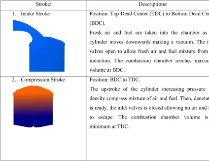
8 cycle also known as the Otto engine cycle. Figure 2.1 shows the four stroke combustion engine cycle.
Figure 2.1: Four Stroke Combustion Engine Cycle.
Table 2.1: The complete working cycle of the four stroke engine (Robert Bosch, 2006).
Stroke: Descriptions:
1. Intake Stroke Position: Top Dead Center (TDC) to Bottom Dead Center (BDC).
Fresh air and fuel are taken into the chamber as the cylinder moves downwards making a vacuum. The inlet valves open to allow fresh air and fuel mixture from the induction. The combustion chamber reaches maximum volume at BDC.
2. Compression Stroke Position: BDC to TDC.
[image:23.595.107.532.412.738.2]9
3. Combustion Stroke Position: TDC to BDC.
Before the piston reaches TDC, the spark plug initiates the combustion of the air and fuel mixture at a given ignition point. Ignited the compressed air and fuel mixture by a spark plug and the explosive expansion of the gases, forces the cylinder downwards. Known as the power stroke, the crankshaft and flywheel is continued motion to creates power.
4. Exhaust Stroke Position: BDC to TDC.
Starting the cycle again with the intake stroke, waste gases are forced out of the combustion chamber via the exhaust port. To allows the hot exhaust gases to escape, the outlet valves are now open.
The admission and outlet ports open and near permit air to be drawn into the chamber and fumes gasses to be removed amid the Intake and Exhaust stroke. We comprehend that the motor is adequately a gadget which sucks in air, packs it, touches off it and after that blows the let some circulation into again to making energy to the street wheels on the ignition stroke. As far as the execution increases conceivable, there are a tremendous large number of various procedures and advances we will cover in motor updates. As a matter of first importance we should get a comprehension of the diverse sorts of motor designs generally found in autos today. As Engines can arrive in a variety of various plans, including Straight, V Type, W Type, Boxer, Rotary Diesel, Hybrid, Electric and even Motorbike Car Engine. Most of the spark-ignition internal combustion engines operate with a stoichiometric air-gasoline ratio since it enables the catalyst to control emissions level (Chalet & Chesse, 2016).