UNIVERSITI TEKNIKAL MALAYSIA MELAKA
POWER FACTOR IMPROVEMENT USING AUTOMATIC
POWER FACTOR COMPENSATION (APFC) DEVICE FOR
MEDICAL INDUSTRIES IN MALAYSIA
This report is submitted in accordance with the requirement of the Universiti Teknikal Malaysia Melaka (UTeM) for the Bachelor of Electrical Engineering
Technology (Industrial Power) with Honours.
by
MARYAM NABIHAH BINTI ZAIDI B071410372
950216-87-5068
UNIVERSITI TEKNIKAL MALAYSIA MELAKA
BORANG PENGESAHAN STATUS LAPORAN PROJEK SARJANA MUDA
TAJUK: Power Factor Improvement using Automatic Power Factor Compensation (APFC) Device for Medical Industries in Malaysia
SESI PENGAJIAN: 2017/18 Semester 1
Saya MARYAM NABIHAH BINTI ZAIDI
mengaku membenarkan Laporan PSM ini disimpan di Perpustakaan Universiti Teknikal Malaysia Melaka (UTeM) dengan syarat-syarat kegunaan seperti berikut:
1. Laporan PSM adalah hak milik Universiti Teknikal Malaysia Melaka dan penulis. 2. Perpustakaan Universiti Teknikal Malaysia Melaka dibenarkan membuat salinan
untuk tujuan pengajian sahaja dengan izin penulis.
3. Perpustakaan dibenarkan membuat salinan laporan PSM ini sebagai bahan pertukaran antara institusi pengajian tinggi.
4. **Sila tandakan ( )
SULIT
TERHAD
TIDAK TERHAD
(Mengandungi maklumat yang berdarjah keselamatan atau kepentingan Malaysia sebagaimana yang termaktub dalam AKTA RAHSIA RASMI 1972)
(Mengandungi maklumat TERHAD yang telah ditentukan oleh organisasi/badan di mana penyelidikan dijalankan)
Alamat Tetap:
26, Lorong Jawi Jaya 11,
Taman Jawi Jaya, 14200 Sg Jawi,
Pulau Pinang
Tarikh: ________________________
Disahkan oleh:
Cop Rasmi:
Tarikh: _______________________
22nd DECEMBER 2017
DECLARATION
I hereby, declared this report entitled “Power Factor Improvement using Automatic Power Factor Compensation (APFC) Device for Medical Industries in Malaysia” is
the results of my own research except as cited in references.
Signature:
APPROVAL
This report is submitted to the Faculty of Engineering Technology of UTeM as a partial fulfillment of the requirements for the degree of Bachelor of Electrical Engineering Technology (Industrial Power) with Honours. The member of the supervisory is as follow:
i
ABSTRAK
Laporan ini membentangkan projek yang direka untuk membetulkan faktor kuasa secara automatik bagi industri perubatan di Malaysia dengan harapan untuk memjadikan penggunaan kos dan tenaga yang cekap, kerana sumber tenaga kini semakin berkurangan disebabkan peningkatan populasi. Faktor kuasa ialah nisbah kuasa sebenar dan kuasa nyata. Takrif ini secara matematik diwakili sebagai kW / kVA di mana kW adalah kuasa aktif dan kVA adalah kuasa nyata (aktif + reaktif). Kuasa reaktif adalah kuasa yang dihasilkan oleh beban magnetik dan induktif untuk menjana fluks magnetik. Peningkatan daya reaktif meningkatkan kuasa jelas supaya faktor kuasa akan berkurangan. Faktor kuasa yang rendah akan menyebabkan industri perlu memenuhi permintaan yang tinggi dan menjadikan penggunaan tenaga kurang cekap. Matlamat utama projek ini adalah untuk meningkatkan faktor kuasa semasa industri perubatan dari 0.85 hingga 0.90. Pampasan faktor kuasa menyumbang kepada pengurangan arus dan meningkatkan kecekapan tenaga sambil mengembangkan kebolehpercayaan perancangan untuk rangkaian tenaga masa depan. Apabila teknologi berkembang, penalti kos dan kecekapan yang beransur-ansur harus dikurangkan. Oleh itu, peranti pampasan faktor kuasa automatik harus menjadi alat yang kos efektif dan lebih kecil dari masa ke masa. Inilah sebabnya projek ini menggunakan peranti boleh atur kerana ia merupakan peranti binaan miniatur.
ii
ABSTRACT
This paper present the project designed to correcting power factor for medical industries in Malaysia automatically. Which with hope to make the cost and energy usage efficient, because the energy source are depleting due to increase in population. Power factor is the ratio of real power and apparent power. This definition is mathematically represented as kW/kVA where kW is active power and kVA is apparent power (active + reactive). Reactive power is the non-working power generated by the magnetic and inductive load to generate magnetic flux. The increase in reactive power increase the apparent power so the power factor will decrease. Low pF will cause the industry to meet high demand thus making it less efficient. The main aim of this project is to increasing the current power factor of medical industries from 0.85 to 0.90. Power factor compensation contribute to reduction in current-dependent losses and increase energy efficiency while expanding the reliability of planning for future energy network. As technology develops, the gradual cost and efficiency penalty should reduce. Therefore, automatic power factor compensation device should become cost-effective and smaller device over time. That is the reason this project is using programmable device as it is a miniature architecture device.
iii
DEDICATION
To my beloved parents, Puan Norshamshida Binti Mohamed Zohdi (mama) and Prof Dr Zaidi Bin Mohd Ripin (ayah) that continuously giving me support and love.
To my lovely siblings, Aminah, Harith and Sulaymann that cherish my days.
To my super-awesome supervisor, En Adlan Bin Ali who always remind me of my progress and keep on giving positive words.
To my friends, especially Afisah that helps me a lot when I’m stuck with my coding and my swag SV team members Alia, Akma and Atiq.
To En Azhan for allowing me to use the Control, Instrumentation and Mechatronic Workshop.
To all lecturers and staff that help this project directly or indirectly.
iv
ACKNOWLEDGEMENT
v
TABLE OF CONTENT
Abstrak i
Abstract ii Dedication iii
Acknowledgement iv
Table of Content v
List of Figures viii
CHAPTER 1: INTRODUCTION 1
1.1 Project Background 1
1.2 Motivation 2
1.3 Problem Statement 2
1.4 Objective 3
1.5 Project Scope 3
CHAPTER 2: LITERATURE REVIEW 4
2.1 Introduction 4
2.2 Power Factor 4
2.3 Power Factor Correction 6
2.3.1 Passive Power Factor Compensation 8
2.3.2 Active Power Factor Compensation 8
2.4 TNB Power Factor Surcharge 9
2.5 The Uses of Capacitor in APFC 11 2.6 Location for Power Factor Compensation 12
vi 2.6.2 Power Factor Correction at Motor Control Centre 13 2.6.3 Power Factor Correction at Substation Transformer 13
2.6.4 Power Factor Correction at Utility Meter 13 2.7 Power Factor in Resistive, Inductive and Capacitive Circuit 13
2.7.1 Purely Resistive Circuit 14
2.7.2 Purely Inductive Circuit 15
2.7.3 Purely Capacitive Circuit 17
2.8 Software and Design 18
2.8.1 Software for Circuit Design 18
2.8.1.1 Proteus 08 19
2.8.1.2 Power World 19
2.8.1.3 ERACS 19
2.8.1.4 Multisim 19
2.8.2 Software for Coding Design 20
2.8.2.1 PIC Compiler 20
2.8.2.2 MicroC 20
2.8.2.3 Matlab 20
2.9 Conclusion 21
CHAPTER 3: PROJECT METHODOLOGY 22 3.1 Project Methodology 22
3.1.1 Research Approach 22
3.2 Flow of the System 23
3.2.1 Voltage Sensing 23
3.2.2 Current Sensing 24
3.2.3 Data Calculation 25
3.2.4 Result Display 26
3.2.5 Power Factor Correcting 27
3.3 Project Flowchart 28
3.3.1 Design using Proteus 30
3.3.2 Insert HEX File into Microcontroller 30
3.3.3 Troubleshoot Simulation 30
vii
CHAPTER 4: RESULT & DISCUSSION 32
4.0 Introduction 32
4.1 Coding Design 32
4.1.1 First Coding Design 33
4.1.2 Finalized Coding 34
4.2 Circuit Design 35 4.2.1 Automatic Power Factor Circuit without Capacitor 35
4.2.2 Finalized Automatic Power Factor Circuit 37
CHAPTER 5: CONCLUSION & FUTURE WORK 38
5.1 Conclusion 38
5.2 Future Research and Recommendation 38
REFERENCES 39
APPENDICES
viii
LIST OF FIGURES
2.2.1 Power triangle 5
2.7.1.1 2.7.1.2 2.7.2.1 2.7.2.2 2.7.3.1 2.7.3.2 3.2.1.1 3.2.2.1 3.2.3.1 3.2.4.1 3.2.5.1 3.3.1
Pure resistive load circuit
Waveform for pure resistive load
Pure inductive load circuit Waveform for pure resistive load
Pure capacitive load circuit
Waveform for pure resistive load
Block Diagram for Voltage Sensing Block Diagram for Current Sensing
Block Diagram for Data Calculation Process Block Diagram for Result Display
Block Diagram for Power Factor Correcting Process Flowchart of the Project
14 15 16 16 17 18 23 24 25 26 27 28
4.1 Software Used for Coding Design 33
4.1.1.1 ‘Demo Limit’ Message Error 33
4.1.1.2 Mathematic Function in the Coding 34
4.1.1.3 Corrected Mathematic Function 34
4.1.2.1 Changing Code 35
4.1.2.2 Coding Successfully Compiled 35
4.2.1.1 Full Circuit Design without Capacitor 36
1
CHAPTER 1
INTRODUCTION
1.1 Project Background
2
1.2 Motivation
This project will make the consumers actually see the effect of high and low power system in their consumption of energy. When the power factor is very low, the may be able to see the effect and reach out to make the operation system change as needed. They can increase the power factor by using the automatic power factor compensation which use capacitor and microcontroller as the main components. Thus, this will help in improving the power factor of a system. Plus, the current demand on energy is increasing day by day and the industries growth are inclining. Plus, according to Ministry of Health Malaysia (MoH), medical industries had been tremendously grow for the past decades, 8% to 10% annually. But on the other hand, the energy sources are depleting due to increase in population.
1.3 Problem Statement
3
1.4 Objective
The main objectives of this project is:
i. To identify the most suitable software to be used.
ii. To design a circuit for automatic operation for Power Factor Compensation. iii. To develop a programming code for the Automatic Power Factor
Compensation (APFC) device.
1.5 Project Scope
This project is focusing on:
i. Improving existing power factor on medical industries in Malaysia. ii. To ensure that power factor is more than 0.9.
4
CHAPTER 2
LITERATURE REVIEW
2.1 Introduction
In this chapter, it emphases more on the important theory and assessment related to the work required in developing the project. A thorough research had been done on the factors that affect power factor and the type of corrective instruments used to execute the desired objectives. Besides, it also shows and proves how it can give benefits to the industries that use high voltage supplies.
There are two type of power factor correction which are fixed and automated, and this project focuses on the automated system. There are few main reasons why the power factor correction (or compensation) need to be automated:
i. Stability – A stable power system means stable voltage supply and fewer faults that can reduced costs (especially in the electricity tariff).
ii. Safety – The needs of automated controls is to ensure that the plant must be safe to operate even when there is instability of power system.
2.2 Power factor
5
𝑃𝑜𝑤𝑒𝑟 𝑓𝑎𝑐𝑡𝑜𝑟 = 𝑅𝑒𝑎𝑙 𝑝𝑜𝑤𝑒𝑟 (𝑘𝑊)
𝑇𝑜𝑡𝑎𝑙 𝑝𝑜𝑤𝑒𝑟 (𝑘𝑉𝐴)× 100
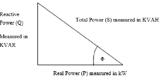
Real power or true power, P is the power that is used to do work on the load. Active power is measured in watts (W) and in the electricity billing, it is stately in kilowatt-hours (kWH). It is the power drawn by the electrical resistance of a system doing useful work. Reactive power is the power not used to do work on the load.
Reactive power, Q is measured in volt-amperes reactive (VAR) and stored in and discharged by inductive motors, transformers or solenoids. The reactive power required by inductive loads increases the amount of apparent power and it is measured in kilovolt amps (kVA) in the distribution systems. But reactive power are not stated in the electrical tariff. Increasing the reactive and apparent power causes the power factor, PF to decrease.
Total power or apparent power is the combination of real power and reactive power. Apparent power is the power supplied to the circuit and is measured in volt-amperes (VA). Total power is the electrical billing statement is measured in volt-ampere-hour (kVAH).
Kanchi et al. (2013) have described that generally, power factor is called as the cosine
of angle between the voltage and current. In an a.c circuits there is generally a phase
[image:18.595.190.449.591.716.2]difference between voltage and current. If the circuit is inductive, the current is lags behind the voltage and the power factor is called lagging power factor and if the circuit is capacitive then current leads to voltage and power factor is said to be leading power factor.
6 The power factor of an alternating-current device or circuit is the ratio of the active power P to the apparent power S. Power factor is expressed as a simple number, or as a percentage. It is given by the equation
Power factor = P/S
where; P = active power delivered or absorbed by the circuit or device [W] S = apparent power of the circuit or device [VA]
The power factor never exceed 100 percent or unity because the value of active power can never be greater than apparent power. Power factor is also a measure of the phase angle between voltage and current. Where this leads to another equation,
𝑃𝑜𝑤𝑒𝑟 𝑓𝑎𝑐𝑡𝑜𝑟 =𝑃 𝑆
= 𝐸𝐼𝑝 𝐸𝐼
= 𝐼𝑝/𝐼
= cos 𝜃
Neha Shrivastava (2015) stated that the AC circuits are made of resistive, inductive and capacitive components. For purely resistive load like incandescent lighting, the current and voltage are in phase where the current follows the voltage. For inductive loads case, the current is out of phase with voltage where it lags behind the voltage except for a few purely resistive loads and synchronous. However, in a capacitive load the current leads the voltage thus means the current and voltage are out of phase. The most common capacitive loads are the capacitors used for the correction of power factor of the load.
2.3 Power factor correction
7 Wildi, T. (2006) mentioned that power factor correction (or improvement) is economically practicable whenever the decrease in the annual cost of electricity exceed the pay back cost of installing the required capacitors. In some cases, the customer has no choice but must obey with the minimum power factor specified by the utility company. The power factor may be amended by installing capacitors at the commercial enterprise or at the service entrance of the factory. In other cases, if the power factor is particularly low, it may be necessary to correct the power factor of the device or machine individually.
Power factor compensation can be defined as a process of correcting the lagging current by producing leading current so that the angle between voltage and current reduces. There will be no power loss if the current and voltage are in phase, thus it can improve the power factor value to nearly unity or even unity. The process is done by connecting few capacitors at the service entrance where the power factor is attuned by an adequate value of capacitance.
The electrical loads that work on alternating current need apparent power which is the product of real power and reactive power. The reason why the electrical load has power factor less than one is, the existence of reactive power makes the apparent power higher than real power. The reactive power increases the current flow from the power sources and the load. When this happens, power losses increases in both distribution and transmission lines. Thus, this results in financial losses for the power provider like Tenaga Nasional Berhad (TNB) which made them require their consumers and customers, especially those who use large loads to maintain their power factor above 0.85 or higher.
8
2.3.1 Passive power factor compensation
Passive PFC needs lager inductor than active PFC but it still cost less. This is an easy way to correct the nonlinearity in a load by using capacitor bank but it is not as effective as active PFC. According to Amin (2012), the simplest way to control the harmonic current is to use a filter: it is probable to design a filter that passes current only at line frequency (50 or 60 Hz). This filter decreases the harmonic current, which means that the nonlinear device now looks like a linear load. At this point the power factor can be conveyed to near unity, using capacitors or inductors as requisite. This filter needs large-value high-current inductors which are huge and costly. Passive PFCs are typically more power efficient than active PFCs. A passive PFC on a switching computer PSU has a typical power efficiency of around 96%, while an active PFC has a typical efficiency of about 94%.
2.3.2 Active power factor compensation
9
2.4 TNB power factor surcharge
According to Tenaga Nasional Berhad (TNB), for customers taking supply at 33 kV or below, the value of the power factor to be retained is more or equal to 0.85. For customers taking supply at 132 kV or above, the value of the power factor to be retained is more or equal to 0.90. If the consumers cannot oblige the value needed, they will be penalised by the power provider in power factor surcharge. A high Power Factor index (e.g. above 0.85 or 0.90) indicates an efficient level of electricity usage. On the other hand, a low Power Factor index (e.g. under 0.85 or 0.90) shows an inefficient use of electricity, indicating electricity wastage.
Plus, according to Ministry of Energy, Green Technology and Water (KeTTHA) regulates the electricity tariffs charged by the utilities to final consumers in Peninsular Malaysia and Sabah in pursuance of the Electricity Supply Act 1990. Among the principles applied in determining tariff rate is:
The tariff should reflect the cost supply.
Provide adequate revenue for the development of the power sector. Competitiveness among the industries and services.
Affordability of the consumers and social economic objectives of the government.
TNB imposes on all industrial and low power consumer to maintain their power factor to no less than 0.85. Failing to maintain the required PF will result on a penalty being imposed on them. The penalty is incorporated into the tariff structure. The consumer should use their best endeavours to obtain highest possible in PF in the operation of any of their electrical installation. Based on TNB, power factor below 0.85 and up to 0.75 (0.85 > 𝑃𝐹 ≥ 0.75) lagging, a supplementary charge 1.5% of the bill for the
month for each 0.01 unit below 0.85 and up to 0.75 lagging PF will be added to the bill for that month. On the other hand, power factor below 0.75 lagging, in addition to the charge payable under the above condition, a supplementary charge of 3% of the bill for that month for each 0.01 unit below 0.75 lagging PF will be added to the bill of the month.
10 competitiveness. Prior to that, the last review was carried out in 1st March 2009. The electricity tariff rate are based on the following guideline:
The amount of energy consumed (kWh)
The maximum demand at which energy consumed (kW) Peak or off peak period
The power factor of the load The connected load
The explanations on load and power factor surcharged can be proven or showed by a simple example which is to make a comparison between two different factory (indicates the industry). Consider two factories A and B consume the same amount of energy (kWh) and have the same maximum demand (kW). However, the power factor of A is unity (1) while B is 0.5.
From the equation of apparent power, (𝑆 = 𝐼. 𝑉) it can be seen that the line current
proportional to the apparent power and factory B draws twice as much current as factory A. The line conductors, transformers, circuit breakers, and other devices supplying energy to B must have twice the rating to those supplying to A. Besides, the utility company must invest more capital to factory B; consequently it is logical that
Factory A
Factory B
Maximum demand = 1000 kW Apparent power = 1000 kVA Power factor = 1.0
Current bill = RM 3000
Maximum demand = 1000 kW Apparent power = 2000 kVA Power factor = 0.5
11 factory B should pay more for its energy, even though it consumes the same amount. As for the TNB power factor surcharged,
Factory A
POWER FACTOR = 0.60
SURCHARGE = No surcharge as the PF is above 0.85
TOTAL BILL = RM 3000.00
Factory B
POWER
FACTOR
= 0.50
SURCHARGE
= [0.85 − 0.75
0.01 × 1.5% × 4000] + [(
0.75 − 0.5
0.01 × 3% × 4000]
TOTAL BILL = RM 6600.00
From the example shown, it can be seen that low power factor will cause the industry to be penalised by TNB and this will make them spend more just to settle their penalty. Therefore, rather than paying higher monthly bill, the power factor should be improved or corrected by using a suitable power factor compensation method.
2.5 The uses of capacitors in APFC