Bachelor of Mechanical Engineering (Hons)
Faculty of Mechanical Engineering
OPTIMIZATION OF SYNTHETIC JET ACTUATOR
LOCATION FOR AERODYNAMIC DRAG REDUCTION OF
BACKWARD-FACING STEP
Teo Yong Soon
OPTIMIZATION OF SYNTHETIC JET ACTUATOR LOCATION FOR AERODYNAMIC DRAG REDUCTION OF BAKWARD-FACING STEP
TEO YONG SOON
A thesis submitted
in fulfillment of the requirements for the Bachelor ofMechanical Engineering (Hons)
Faculty of Mechanical Engineering
UNIVERSITI TEKNIKAL MALAYSIA MELAKA
DECLARATION
I declare that this thesis entitled “Optimization of Synthetic Jet Actuator Location for
Aerodynamic Drag Reduction of Backward-facing Step” is the result of my own research
except as cited in the references. The thesis has not been accepted for any degree and is not
concurrently submitted in candidature of any other degree.
Signature : ...
Name : ...
DEDICATION
APPROVAL
I hereby declare that I have read this dissertation/report and in my opinion this
dissertation/report is sufficient in terms of scope and quality as a partial fulfillment of
Bachelor of Mechanical Engineering (Hons).
Signature :………. ...
Supervisor Name :……… ...
i
ACKNOWLEDGEMENT
First, I would like to take this opportunity to express my grateful thanks to my supervisor Dr. Cheng See Yuan from Faculty of Mechanical Engineering University Teknikal Malaysia Melaka (UTeM) who had supervised, supported and guided me during this final year project. Besides, I appreciate the patient and generosity of Dr. Cheng See Yuan on teaching me about the ANSYS software.
After that, I would also like to express my grateful thanks to Msc. Jeffrey from Faculty of Mechanical Engineering University Teknikal Malaysia Melaka (UTeM) who had advised, helped and supported me during this final year project. I appreciate his patient on teaching me on the thesis writing.
ii ABSTRACT
iii ABSTRAK
iv
TABLE OF CONTENTS
PAGE DECLARATION
DEDICATION APPROVAL
ACKNOWLEDGEMENTS i
ABSTRACT ii
ABSTRAK iii
TABLE OF CONTENTS iv
LIST OF TABLES vi
LIST OF FIGURES vii
LIST OF ABBREVIATIONS x
LIST OF SYMBOLS xi
CHAPTER
1. INTRODUCTION 1
1.1 Background 1
1.2 Problem Statement 3
1.3 Objective 4
1.4 Scope of Project 4
2. LITERATURE REVIEW 5
2.1 Introduction 5
2.2 Synthetic Jet Actuator in Backward-facing Step Domain 7
2.3 Aerodynamics Drag 11
2.3.1 Boundary layer 11
2.3.2 Wake or flow separation 12
2.3.3 Drag reduction 13
2.4 Computational Study 14
2.4.1 Meshing 14
2.4.2 Turbulence model 15
2.4.3 Reynolds-Averaged Navier-Stokes (RANS)
equation 16
2.4.4 Profile, contour and vector Plot 16
3. METHODOLOGY 18
3.1 Introduction 18
3.2 Synthetic Jet into Quiescent Flow 20
3.2.1 Geometry 21
3.2.2 Meshing 22
3.2.3 Fluent Setting 24
3.2.4 Validation and verification 25
v
3.2.4.2 Sensitivity test on different domain size 26 3.2.4.3 Sensitivity test on different time step size 27 3.2.4.4 Sensitivity test on different boundary condition 29
3.3 Flow in Backward-facing Step 30
3.3.1 Geometry 30
3.3.2 Meshing 31
3.3.3 Fluent setting 32
3.3.4 Validation and verification 34
3.3.4.1 Validation result 34
3.3.4.2 Grid independency test 35
3.3.5 Result comparison 36
4. RESULT AND DISCUSSION 38
4.1 Synthetic Jet Actuator Location in the Backward-facing Step for
All Cases 38
4.2 Effect of the Synthetic Jet Actuator Location in the
Backward-facing Step on the Aerodynamic Drag 39
5. CONCLUSION AND RECOMMENDATIONS FOR FUTURE
RESEARCH 46
vi
LIST OF TABLES
TABLES TITLE PAGE
2.1 Synthetic jet actuator locations (He Y. et al. 2001) 9 2.2 Cases with different forcing frequency and SJA location (Kotapati R.
et al. 2006) 10
2.3 Location and size of separation bubble for different cases (Kotapati R.
et al. 2006) 11
3.1 Drag coefficient of different mesh cells 35
4.1 All Computational Cases 38
4.2 Aerodynamic properties of all cases 40
4.3 Drag and lift properties of uncontrolled case (Case 0) 42
vii
LIST OF FIGURES
FIGURE TITLE PAGE
2.1 Schematic of general Synthetic Jet Actuator (Zhou et al. 2015) 6
2.2 Schematic of Synthetic Jet Actuators 6
2.2 (a) Single diaphragm (Xiong et al. 2010) 6
2.2 (b) Double diaphragm (Kurowski et al. 2015) 6
2.3 Synthetic jet formation parameters (Murugan et al. 2016) 7 2.4 Lift coefficient increment at different jet locations (Zhao G. et al
2014) 9
2.5 Mean streamwise velocity field and separation bubbles streamlines
(Dandois J. 2006) 10
2.5 (a) Uncontrolled flow (Dandois J. 2006) 10
2.5 (b) Low frequency controlled flow (Dandois J. 2006) 10 2.5 (c) High frequency controlled flow (Dandois J. 2006) 10
2.6 Types of boundary layers (Fox R.W. et al. 2010) 12
2.7 Flow separation occur inside a wide angle diffuser (Cengel Y.A. et al
2006) 13
2.8 Classification of the flow control techniques (El-Alti M. et al. 2012) 14 2.9 Structured and unstructured mesh (Cengel Y.A. et al 2006) 15
2.10 Types of plot (Cengel Y.A. et al 2006) 17
2.10 (a) Profile plot (Cengel Y.A. et al 2006) 17
2.10 (b) Vector plot (Cengel Y.A. et al 2006) 17
2.10 (c) Contour plot (Cengel Y.A. et al 2006) 17
3.1 Simulation Flow Chart 19
3.2 Modelling and Simulation phases and V&V roles (Schlesinger, S. et
al. 1979) 20
3.3 (a) Verification Process (Oberkampf, W.L. et al. 2002) 20 3.3 (b) Validation Process (Oberkampf, W.L. et al. 2002) 20
3.4 Dimension of synthetic jet actuator model 21
3.5 Geometry of synthetic jet actuator model 22
3.6 Mesh of synthetic jet actuator model 23
3.7 Boundary condition of the fluid domain (left) and synthetic jet
actuator (right) 23
viii
3.9 Comparison of the time-averaged velocity distributions between
experiment results and synthetic jet actuator model at z = 9.8mm 26 3.10 Graph of average z-velocity versus flow time at orifice exit for
domain size 161Do, 181Do and 201Do
27
3.11 Graph of average z-velocity versus flow time at orifice exit for time step size 8.33x10⁻⁶ (120 time step per cycle), 5.56x10⁻⁶ (180 time step
per cycle) and 4.17x10⁻⁶ (240 time step per cycle)
28
3.12 Graph of average z-velocity versus flow time at orifice exit for
periodic boundary condition and symmetry boundary condition 29 3.13 Graph of z-velocity versus x-axis position at orifice exit for periodic
boundary condition and symmetry boundary condition 30
3.14 Dimension of backward-facing step model 31
3.15 Geometry of backward-facing step 31
3.16 Mesh of backward-facing step 32
3.17 Boundary condition of the backward-facing step 32
3.18 User-defined function of the synthetic jet velocity profile 33
3.19 Time-averaged streamwise velocity x/h + u/U∞(solid line: RANS,
dotted line: DNS)
34
3.20 Graph of average drag coefficient at slope versus number of mesh
cells 36
3.21 Graph of drag coefficient versus flow time at the slope for four
different mesh cells 36
4.1 Streamline profile of the uncontrolled flow case (Case 0) and the
location of the separation point 39
4.2 Streamline profile of the controlled flow case (Case 1) and the
location of the reattachment point 39
4.3 Graph of drag coefficient versus flow time at the slope for all cases 40 4.4 Graph of lift coefficient versus flow time at the slope for all cases 41 4.5 (a) Pressure contour of all cases after blowing stroke at t = 4.5x10⁻³s –
Case 0 43
4.5 (b) Pressure contour of all cases after blowing stroke at t = 4.5x10⁻³s –
Case 1 43
4.5 (c) Pressure contour of all cases after blowing stroke at t = 4.5x10⁻³s –
Case 2 43
4.5 (d) Pressure contour of all cases after blowing stroke at t = 4.5x10⁻³s –
Case 3 43
4.5 (e) Pressure contour of all cases after blowing stroke at t = 4.5x10⁻³s –
Case 4 43
4.6 (a) Streamline profile of all cases – Case 0 44
4.6 (b) Streamline profile of all cases – Case 1 44
4.6 (c) Streamline profile of all cases – Case 2 44
4.6 (d) Streamline profile of all cases – Case 3 44
ix
4.7 (a) Vorticity contour of all cases – Case 0 45
4.7 (b) Vorticity contour of all cases – Case 1 45
4.7 (c) Vorticity contour of all cases – Case 2 45
4.7 (d) Vorticity contour of all cases – Case 3 45
x
LIST OF ABBREVIATIONS
AFC Active Flow Control
SJA Synthetic Jet Actuator ZNMF Zero-Net Mass-Flux
RANS Reynolds-Average Navier-Stokes
URANS Unsteady Reynolds-Average Navier-Stokes SST Shear Stress Transport
AOA Angle of Attack
PIV Particle Image Velocimetry FDM Finite Difference Method FEM Finite Element Method FVM Finite Volume Method
xi
LIST OF SYMBOLS
Ma Mach Number
Re Reynolds Number
c Chord Length
α Angle of Attack
fJ Forcing Frequency
fSEP Separation Bubble Frequency
fSL Shear Layer Frequency
xSEP Separation Location
LSEP Separation Bubble Length
△LSEP Separation Bubble Length Increment
HSEP Separation Bubble Height
ρ Density
v Velocity
FD Drag Force
A Frontal Area
CD Drag Coefficient
△CD Drag Coefficient Increment
CL Lift Coefficient
△CL Lift Coefficient Increment
xi Location in x-direction
xj Location in y-direction
xs Separation Point Location in x-direction
xr Reattachment Point Location in x-direction
Fi Force in x-direction
FDP Pressure Drag Force
FDV Viscous Drag Force
FLP Pressure Lift Force
FLV Viscous Lift Force
vi Velocity in x-direction
vj Velocity in y-direction
vSJA Synthetic Jet Velocity
vmax Maximum Jet Velocity
µ Kinematics Viscosity
xii
zcavity wall Cavity wall Location in z-direction
A Amplitude
f Frequency
t Time
Do Orifice Width
1 CHAPTER 1
INTRODUCTION
1.1Background
Aerodynamics flow control technique has been widely researched and developed in
order to improve the aerodynamics properties in several sectors. Among the aerodynamics
flow control techniques, active flow control (AFC) is one of the types of aerodynamics
flow control techniques which are usually used in manipulating the boundary layer to
improve aerodynamics properties in various applications. Those applications consist of
drag reduction, lift augmentation, noise mitigation and mixing enhancement. In the active
flow control device, momentum or energy is always added to the flow in a regulated
manner in order to help in the control of the fluid flow. In the past decades, plenty of
researches showed that active flow controls technique has provided solution for the
problem faced by the aerodynamic transport applications and electronic cooling
applications. Active flow control technique device such as synthetic jet actuator had helped
to reduce aerodynamics drag of the vehicle for about 15.83% in suction and 14.38% in
blowing (Harinaldi et al. 2011). Besides that, an appropriate combination of jet arrays in
active flow control technique had increase both lift coefficient and drag coefficient of the
passenger van by 100% and 26.5% respectively (Zhao G. et al. 2014). For active flow
2
aspect ratio orifices had a best result in the heat transfer (Lee et al. 2016).
Synthetic jet actuator (SJA), also can be called as Zero-Net Mass-Flux (ZNMF)
actuator is a device that uses in active flow control technique by using synthetic jet
produces by a vibrating membrane through an orifice. In fluid dynamics, synthetic jet flow
is a type of jet flow which is usually created by an actuator with one or two vibrating
diaphragm where the stream of one fluid mixes with the surrounding medium (Kurowski et
al. 2015). In flow control applications, SJA is use to create a formation of vortex ring pair
in order to impart momentum on the boundary layer of the flow. The performance of the
synthetic jet usually depends on either the parameter of the actuator or the properties of the
fluid. The various parameters of the actuator that influence the performance of the
synthetic jet are normally diaphragm vibration properties, cavity dimensions, cavity shape,
orifice dimensions and orifice shape. According to the research of the past decades, the
performance of the synthetic jet is based on the velocity of the synthetic jet, vorticity and
pressure contours produce by the synthetic jet. In active flow control, the cavity shapes of
the actuator did not have large impact on the performance of the synthetic jet (Feero et al.
2015). Besides that, for different actuator’s parameters, different excitation frequency of
the diaphragm will have difference performance (Lv Yuan-wei et al. 2014). This study
shows that the performance of the synthetic jet can be achieves by finding the optimal
design for each parameter and the suitable excitation frequency for the actuator. Moreover,
by using double vibrating diaphragm and higher vibrating amplitude, the results showed
massive increasing in the jet velocity with the same membrane and cavity resonant
3
A bluff body in fluid mechanics can be defined as a body that the drag force experience
by the body is dominant by pressure drag due to the shape of the body which has separated
flow over a substantial part of its surface. A bluff body flow involve in interaction of 3
shear layers which will influence the aerodynamics properties which are boundary layer,
separating free shear layer and the wake. In the aerodynamics of bluff body, the
aerodynamics properties improvements that will usually be consider are the aerodynamic
drag reduction, lift enhancement, vibration and noise reduction. In order to achieve those
improvements, it is important to control the wake and the dynamics of vortex formations
which acts as the source of fluid forces of the bluff body (Efstathios Konstantinidis et al.
2016). Those controls can be done by using passive or active flow control techniques.
1.2Problem Statement
Aerodynamic properties such as aerodynamic drags of the bluff body such as building
and transportation acts as an importance factors in reducing power consumption and higher
height construction probability. Therefore, the active flow control device such as synthetic
jet actuator was introduced to help in the reducing the aerodynamic drag of the bluff body.
In order to achieve a better drag reduction of the bluff body, it is necessary to study the
4 1.3Objective
The objectives of this final year project are as follows:
1. To find an optimal design on the location of the synthetic jet actuator in the
backward-facing step.
2. To study the effect of the synthetic jet actuator position in the backward-facing step
on the aerodynamic drag of the bluff body.
1.4Scope of Project
The scopes of this final year project are:
1. Only the effect of the synthetic jet actuator’s location on the aerodynamic drag in
the backward-facing step will be study in this report.
2. Turbulence flow will be simulated inside the backward-facing step.
3. The analysis of the performance of the synthetic jet and aerodynamic drag of the
bluff body will be conduct by using simulation by ANSYS-Computational Fluid
5 CHAPTER 2
LITERATURE REVIEW
2.1 Introduction
Active flow devices have a high potential to use in jet’s thrust vectoring, mixing
enhancement, heat transfer, drag reduction and separation in flow regimes reduction
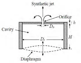
(Saambavi et al. 2014). A general synthetic jet actuator (SJA) (Fig. 2.1) is one of the types
of active flow control device that contains of a cavity with an oscillating diaphragm and a
small orifice (Zhou et al. 2010). There were also some different kinds of orientation of
diaphragm of the synthetic jet actuator such as double diaphragm parallel to the orifice exit
(Fig. 2.2(b)) (Kurowski et al. 2015) and single diaphragm parallel to the orifice exit (Fig.
2.2(a)) (Xiong et al. 2013). The generation of the synthetic jet was caused by the volume
change in the cavity due to the fluctuation of the oscillating diaphragm. During the suction
stroke, the diaphragm of the SJA will move downwards and causes the fluid from the
surrounding medium to enter the cavity. During blowing stroke, the diaphragm of the SJA
will move upwards, causing the fluid inside the cavity push out from the cavity through the
small orifice in the form of a jet. When the fluid pass through the orifice during both
suction and blowing stroke, a shear layer will form which causing a rolling vortex ring
formed at the orifice (Zhou et al. 2010). The formation of synthetic jet is governed by some
6
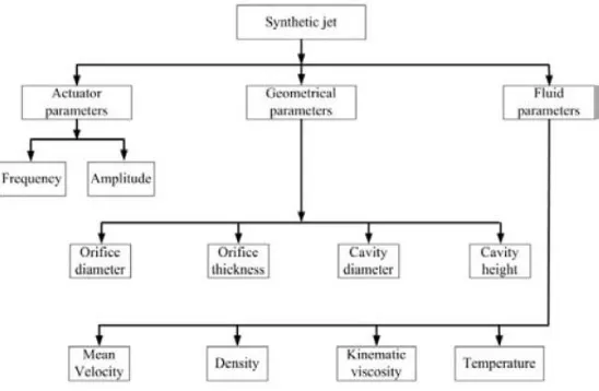
and the fluid domain parameters (Fig. 2.3). Besides than the actuator and fluid parameters,
the synthetic jet can also be characterised by the non-dimensional parameters such as
[image:23.595.224.364.204.313.2]Reynolds number, Strouhal number, Stokes number and stroke ratio (Murugan et al. 2016).
Figure 2.1: Schematic of general Synthetic Jet Actuator (Source: Zhou et al. 2015)
(a) (b)
[image:23.595.104.474.373.522.2]7
Figure 2.3: Synthetic jet formation parameters (Source: Murugan et al. 2016)
2.2 Synthetic Jet Actuator in Backward-facing Step
Many recent studies and researches had conducted the effect of the different in the
location of the synthetic jet actuator in the backward-facing step. In the study done on the
effect of the synthetic jet control on the separation, the simulation conducted by using
unsteady coupled turbulence k-ω SST Reynolds-Averaged Navier-Stokes (URANS)
equations with subsonic stream flow of Ma = 0.4 on the OA213 rotor airfoil. The oscillating diaphragm motion of the SJA on the airfoil was replaced with a sinusoidal
velocity boundary condition with orifice width of 1%c, oscillatory frequency and
momentum of 1.0 and 0.0007 respectively. In the simulation for the analysis of jet
locations at 5%c, 15%c, 30%c, 45%c and 60%c, the results showed that at small AOA and
high AOA, placing the SJA at 15%c and 5%c has the best effect on lift increment
respectively. Besides, they also study the combination of jet array on the effect of the lift
increment and the results showed that the jet arrays have a better effect on the lift