This is a repository copy of
Efficient object localization using sparsely distributed passive
RFID tags
.
White Rose Research Online URL for this paper:
http://eprints.whiterose.ac.uk/150786/
Version: Accepted Version
Article:
Yang, P. orcid.org/0000-0002-8553-7127, Wu, W., Moniri, M. et al. (1 more author) (2013)
Efficient object localization using sparsely distributed passive RFID tags. IEEE
Transactions on Industrial Electronics, 60 (12). pp. 5914-5924. ISSN 0278-0046
https://doi.org/10.1109/tie.2012.2230596
© 2012 IEEE. Personal use of this material is permitted. Permission from IEEE must be
obtained for all other users, including reprinting/ republishing this material for advertising or
promotional purposes, creating new collective works for resale or redistribution to servers
or lists, or reuse of any copyrighted components of this work in other works. Reproduced
in accordance with the publisher's self-archiving policy.
[email protected] https://eprints.whiterose.ac.uk/ Reuse
Items deposited in White Rose Research Online are protected by copyright, with all rights reserved unless indicated otherwise. They may be downloaded and/or printed for private study, or other acts as permitted by national copyright laws. The publisher or other rights holders may allow further reproduction and re-use of the full text version. This is indicated by the licence information on the White Rose Research Online record for the item.
Takedown
If you consider content in White Rose Research Online to be in breach of UK law, please notify us by
This is a repository copy of
Efficient Object Localization Using Sparsely Distributed
Passive RFID Tags
.
White Rose Research Online URL for this paper:
http://eprints.whiterose.ac.uk/150786/
Version: Accepted Version
Article:
Yang, P orcid.org/0000-0002-8553-7127, Wu, W, Moniri, M et al. (1 more author) (2013)
Efficient Object Localization Using
Sparsely Distributed Passive RFID Tags. IEEE
Transactions on Industrial Electronics, 60 (12). pp. 5914-5924. ISSN 0278-0046
https://doi.org/10.1109/tie.2012.2230596
[email protected] https://eprints.whiterose.ac.uk/ Reuse
Items deposited in White Rose Research Online are protected by copyright, with all rights reserved unless indicated otherwise. They may be downloaded and/or printed for private study, or other acts as permitted by national copyright laws. The publisher or other rights holders may allow further reproduction and re-use of the full text version. This is indicated by the licence information on the White Rose Research Online record for the item.
Takedown
If you consider content in White Rose Research Online to be in breach of UK law, please notify us by
Abstract—Radio-Frequency Identification (RFID) technology has been widely used in passive RFID localisation application due to its flexible deployment and low-cost. But current passive RFID localisation systems cannot achieve both highly accurate and precise moving object localisation task owing to tag collisions and variation of the behavior of tags. Most researchers increase the density of tag distribution to improve localisation accuracy, and then consider using either anti-collision process embedded in the hardware of the RFID reader or advanced localisation algorithms to enhance localisation precision. However, advanced anti-collision processes for RFID devices are challenged by the physical constraint characteristics of radio frequency; and improved localisation algorithm cannot fundamentally reduce the impacts of tag collision on localisation precision. This research work attempts to improve localisation precision of a passive RFID localisation system by using sparsely distributed RFID tags. This paper first defines a measure for accuracy and precision in a passive RFID localisation system with regard to RFID Tag Distribution. An exponential based function is then derived from experimental measurements, which reflects the relationship between RFID Tag Distribution and localisation precision. This function shows that localisation precision is mainly determined by tag density of RFID Tag Distribution. Based on the experimental findings, a sparse RFID Tag Distribution approach is proposed. The results show that in comparison with the conventional RFID Tag Distribution; passive RFID localisation system with sparse RFID Tag Distribution can deliver a higher localisation precision for the required accuracy.
Index Terms— RFID, accuracy, precision, object localisation, Tag Distribution
I. INTRODUCTION
HE concept of RFID (Radio Frequency Identification), which is recently used in numerous industrial applications from asset tracking to supply chain management [1-5], has received significant attention among the researchers [6]. The fundamental of this technology is that a spectrum of radio frequency is used to transfer the identification information between two communication devices: RFID tags and RFID readers. Compared with the existing identification technologies such as barcode technology [7], the RFID technology owns a longer working distance and faster reading ability. Many researchers have considered the utilization of RFID technology as an alternative tracking and localisation system, particularly for indoor moving object localisation applications. The fundamental idea of this solution is to localise the moving
object by using RFID tags as landmarks in the environment [8-12] [17]. This is similar to tracking robots in a dense environment [13-15]. A typical RFID localisation system consists of three stages; these are hardware selection, tag distribution and localisation algorithm selection. As for typical indoor moving object localisation applications, accuracy and precision are two important concepts: accuracy is the ability of the system being able to measure the minimum moving distance of an object; precision is the ability of the system being able to reach how closely and consistently the further measurements can be performed to obtain the ideal accurate result. In RFID localisation systems, accuracy and precision can be influenced by the design of RFID infrastructure and the choice of localisation algorithms. This paper focuses on studying the influence of RFID tag distribution on accuracy and precision in normal conditions, which are mostly under a non-emergency indoor environment.
In terms of the achievable localisation accuracy, the available RFID based localisation systems can be generally classified into two major categories: active RFID localisation system and passive RFID localisation system. The active RFID localisation system uses active RFID tags as landmarks for localizing indoor moving objects. Due to the long effective sensing distance, active RFID tags can be usually distributed in 3D environment and applied during adverse conditions, e.g. a fire. A typical case is LANDMARC system [16], which is a region location sensing prototype system that uses active RFID technology for locating moving objects inside buildings. The major advantage of LANDMARC is that it can improve the overall accuracy of locating moving objects to 1 meter by utilizing the concept of reference tags. However, this overall accuracy is unstable and fluctuates due to the variation of the behavior of tags. Similarly, Chae and Han [18] presented a localisation system for mobile robots by fusing the RFID sensor and the vision sensor. The active RFID tags would localize the global position of moving robots; and then the vision sensor would localize the local pose of moving robots. While the method can achieve accuracy up to 0.25 meter, it is not a standalone RFID localisation system. Therefore, the key drawback of active RFID localisation system is that the localisation accuracy is limited to a meter level due to false-positive reading error. The RFID reader can easily detect some unexpected tag ID since active tags continuously send radio signal. On the other hand, the long latency and variation of the behavior of tags limits the increased accuracy and localisation range.
Efficient Object Localisation Using Sparsely
Distributed Passive RFID Tags
Po Yang, Wenyan Wu, Mansour Moniri and Claude C Chibelushi
Passive RFID localisation systems [20-23] overcome many of these problems. Zhang et.al.[19] examined the possibility of using direction-of-arrival estimation method to localize the object’s position in a passive RFID tag distribution environment. Park et.al.[20] presented an efficient localisation algorithm by using highly dense passive tag distribution for mobile robot application, which can improve the localisation accuracy to 5.5 centimeters. This system reads passive RFID tags and computes their absolute position on the floor. The passive RFID localisation system can utilize high density RFID passive tag distribution to enhance the localisation accuracy; but has some limitations. The first limitation is that the high density tag distribution would increase the RFID tag collisions [24], which is due to the reduction of the distance and the greater variation of the behavior of tags. In this case, the precision of moving object localisation is reduced. The second limitation is that the high density distribution of RFID tags requires a large number of RFID tags, which makes the setup difficult and increases cost. With regard to this problem, the possibility of deploying various types of patterns for highly dense tag distribution is studied, such as random uniform and regular pattern tag distributions. Also, while passive RFID localisation system can achieve a higher accuracy than active RFID localisation system, it needs a high quality anti-collision algorithm and a sufficiently high scan range of RFID infrastructure to support it. Han et.al.[21] proposed an efficient localisation scheme with a triangular pattern based RFID passive tag distribution for mobile robot in a highly dense tag distribution environment, which reduces localisation accuracy up to 10 centimeters. But the precision improvement of this localisation scheme comes from the contribution of localisation algorithm, not from the enhanced design of tag distribution in a highly dense environment.
Consequently, the efficient improvement of both accuracy and precision is a key challenging issue in current passive RFID localisation systems. Most researchers focus on increasing the tag distribution density to improve localisation accuracy, and then use either anti-collision process [24] embedded in the hardware of the RFID reader or advanced localisation algorithms [19], [28],[29] to enhance the localisation precision. However, advanced anti-collision processes for RFID devices are challenged by the physical constraint characteristics of Radio Frequency, due to the scattering and reflection of the transition signal which causes interference. The other solutions for improving localisation precision at algorithm level cannot fundamentally reduce the impacts of tag collision on localisation precision. The motivation of this research work is to find a RFID localisation solution for use normal conditions at the tag distribution stage for improving localisation precision, which essentially refers to the distribution of passive RFID tags. The major advantage of the consideration to improve localisation precision by using enhanced tag distribution is that the procedure of deploying passive RFID tags is independent to either the physical constraint characteristics of RFID hardware or the selected localisation algorithms. The application of advanced RFID hardware or improved localisation algorithms in passive RFID localisation systems can still be valid and effective. This paper investigates the use of sparse RFID tag distribution to improve the localisation precision in passive RFID localisation systems, for the required localisation
accuracy.
The influencing factors of tag distribution on accuracy and precision of passive RFID localisation systems are first investigated and defined, which are tag density and tag distance. A trial-and-error experimental approach is then adopted to explore the effect of these two factors of tag distribution on localisation accuracy and precision. Experimental results show that under the fully covered passive RFID tag distribution grid pattern; there is a trade-off between achievable localisation accuracy and precision in passive RFID localisation systems. A sparse RFID tag distribution strategy is proposed to enhance the system reading efficiency of passive RFID localisation systems and avoid the loss of localisation accuracy. The proposed technique is validated by a number of experiments to prove its efficiency on improving the precision with a required accuracy. The validation results show that the proposed method is superior to conventional grid pattern based tag distribution method in terms of localisation precision achieved for a given accuracy. The major contributions of this paper are as follows: 1.A measure model for RFID tag distribution is proposed to qualitatively benchmark localisation accuracy and precision in passive RFID localisation systems.
2.An exponential based function is derived by experimental observations that describe the relationship between tag density of RFID tag distribution and uncertainties of RFID system.
3.A sparsely distributed passive RFID tags design strategy is proposed, that is capable of improving localisation precision for a given accuracy.
The rest of the paper is organized as follows. Section 2 gives an introduction to passive RFID localisation system including the concept of accuracy and precision. Section 3 describes the proposed experimental solution, which contains the experimental platform, design, results and analysis. Section 4 and 5 present the design of the proposed sparse RFID tag distribution strategy and their experimental validation results respectively. Section 6 gives a summary of the conclusions and future work.
II. PASSIVE RFID LOCALISATION OF MOVING OBJECTS
A. Localisation Accuracy, Precision and Efficiency
The concept of localisation accuracy, precision and efficiency in this paper can be clearly defined as follows:
Accuracy: is the ability of the solution or system being able to
measure the minimum moving distance of an object. In passive RFID localisation systems, accuracy is normally limited to the minimum distance between two adjacent tags of a passive RFID tag distribution pattern. Accuracy only considers the value of mean distance errors.
Precision: is the ability of the solution or system being able to
reach how closely and consistently the further measurements can be performed to obtain the ideal accurate result. Precision considers how consistently the localisation system works. In passive RFID localisation systems, precision is influenced by many factors, such as environment noise, signal strength, tag collision etc.
Efficiency: is the ability of the solution or system being able to
Some compromise between “suitable” accuracy and other characteristics is needed.
Thus, the measurements of a passive RFID based localisation system can include the value, an error term and the units, such as 10 centimeters + /- 2.56 centimeters (i.e., accuracy is up to 10 centimeters and precision is within 2.56 centimeters).
B. Fundamentals of Passive RFID Based Localisation
[image:5.612.321.564.444.631.2]In a typical passive RFID based localisation system, moving objects are usually attached to RFID readers and multiple tags are used to be distributed on the floor to locate objects. RFID tag is used to mark a preliminary defined position point; RFID reader is usually attached to a moving object. The localisation technique is expected to enable the RFID reader to efficiently gather information and understand the context of the environment by using RFID tag’s location as well as stored information. Fig.1 illustrates a moving object in a passive RFID localisation system. RFID reader in Fig.1 is assumed to read multiple passive RFID tags at each moving step. The position of targeted moving object is denoted as O x y z( , , ), which is equal to the position of RFID reader. Z represents the height of RFID reader, which is equal to the distance RH from antenna plane of RFID reader to RFID tags distribution plane. M represents the number of passive RFID tags having been detected by RFID reader at each time interval t .{x1,y1},{ ,x y2 2},...{xm,ym} represent the coordinates of passive RFID tags being detected. At each time interval t , there is a spatial relationship between the position of targeted object and these coordinates as shown in Equation (1), where fx an f respectively represent localisation algorithms to y calculate the position of the targeted object from captured RFID data.
Fig. 1 Fundamentals of passive RFID localisation system
From Fig.1, it can be seen that this paper actually focuses on 2D localisation of an indoor moving object with passive RFID localisation system; since the height of RFID reader is usually fixed. Typically, the accuracy and precision in a passive RFID localisation system can be influenced by the design of RFID infrastructure and the choice of localisation algorithms. This paper focuses on studying the distribution of RFID tags on improving accuracy and precision. Thus, a simple and effective
localisation algorithm proposed with the best localisation accuracy by Han [21] is chosen to process RFID data from each time step to calculate the object position, as follows:
Min(1 2, ,... ) Max(1 2, ,... ) 2
Min(1 2, ,... ) Max(1 2, ,... ) 2
x x xm x x xm fx
y y ym y y ym fy
(1)
C. Grid Patterns and Tag Distribution
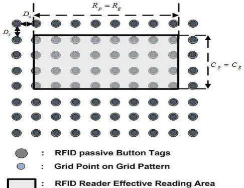
Grid patterns are the drawing templates for tag distribution. The well-proportioned grid pattern has been used for distributing tags in most passive RFID localisation systems [19][20]. This is done to guarantee the equivalent accuracy as the reader moves from one location to another. Also, the antenna used in RFID reader of this research is a directional antenna with dimensions 614×334×25 mm. During the evaluation of sensing range (the height between RFID reader and tags), the effective read range for credit card size tag and button tag are around 35 centimeters and 2–3 centimeters respectively. On the condition of card tags, the sensing range is higher enough to model the antenna as an ellipse shape; but on the condition of button tag, the sensing range is too smaller so that the antenna has to be modeled as a rectangle with identical size of antenna. As illustrated in Fig.2, a well-proportioned grid pattern can be presented by denoting four parameters C , p R , p Dxand D in an effective detection y area of RFID reader antenna, where C is the number of grid p
points placed on each column of the grid pattern; R is the p
number of grid points placed on each row of the grid pattern;
x
D is the distance between each two neighbouring grid points along the row direction of the grid pattern; D is the distance y
between each two neighbouring gird points along the column direction of the grid pattern.
Fig. 2 Grid pattern fully distributed by passive RFID tags
Most passive RFID object localisation systems [19] [20] would place RFID Tags on each grid point of the Grid pattern covering full area, where Cg and Rgrepresent the number of passive
III. MEASURE MODEL FOR ACCURACY AND PRECISION
This section defines a model with few equations, which are used to separately measure the accuracy, precision and efficiency in a passive RFID localisation solution. With a grid pattern as shown in Fig. 2, The number of grid points designed in an effective detection area of RFID reader antenna can be denoted as N , the number of passive RFID tags distributed in an effective detection area of RFID reader antenna can be denoted as M, where N and M satisfy Equation (2).
p p
g g
N C R
M C R
(2)
A. Measure for Localisation Accuracy and Precision
Typically, the accuracy and precision of a passive RFID localisation system are affected by many influencing issues, i.e. the type, position, and direction of tags; the moving speed of camera; the type, position and angle of antenna; the power, type, gain, frequency range, and number of antenna; the work environment and localisation algorithm. This work merely focuses on the impacts of RFID tag distribution on localisation accuracy and precision in a passive RFID localisation system. The localisation algorithm used for verification is based on Equation (1), as long as at least one new tag ( , , ... )
1 2 Min x x x
m ,
( , , ... ) 1 2 Max x x x
m , Min y( 1,y2, ...ym) or Max y( 1,y2, ...ym) is theoretically detected along moving direction. New position of RFID reader should be identified, as shown in Fig.3. In this situation, localisation accuracy is merely decided by the parameters DxandDy. The first equation of this model to measure the localisation accuracy can therefore be written as:
Accurracy : Ax Dx Ay Dy
(3)
The measure of localisation precision in a passive RFID localisation system is related to various factors, even with a known localisation algorithm. In order to evaluate the impacts of tag distribution on localisation precision, a benchmark named as system reading efficiency is used to reflect the successful detection ability of a passive RFID localisation system. System Reading Efficiency (SRE) is defined as the ratio of the number of successful RFID tag readings to the total number of RFID tag readings attempted. The practical value of SRE can be a value between “0” and “1”. As for tag distribution, the value of SRE would be relevant to the number of passive RFID tags distributed in an effective detection area of RFID
Fig.3 Theoretical situation of Equation (1) on keeping accuracy with the reduced number of RFID tags.
reader antenna M. The impact of tag distribution on SRE can be defined by a function, which is relevant to the parameter M; this function can be written as:
( ) ( , ) SRE f M f C Rg g
F (4)
Considering that passive RFID tags are produced by the same manufacturer, the detection ability of individual passive RFID tag is approximately equivalent, so FSRE can be assumed as the probability of an individual passive RFID tag being detected within an effective reading area of RFID reader. Practically, localisation algorithm used in Equation (1) requires at least one new tag being practically detected along moving direction, new position of RFID reader could then be identified. Consequently, precision can be measured by the possible number of RFID tags being detected along each border of RFID reader. The measure for localisation precision can be written as:
( ) ( ) Precision : x g SRE g
y g SRE g
P R F R f M
P C F C f M
(5)
B. Experimental Measure for SRE
passive tags, interval is more suitable than real time continuous observation in this case. An evaluation function is defined in this experimental solution to measure SRE. Each time interval denoted as t, and the total number of sampling times denoted as T; at each individual time interval, RFID reader is assumed to practically detect a certain number of passive RFID tags mt; the expected number of passive RFID tags being detected could be presented by Mt, which is equivalent to M in Equation (2). SRE can be calculated by using Equation (6).
1 1
T T
t t
g g
m m
SRE
M T C R T
(6)
Where: SRE is value of System Reading Efficiency;Tis the total number of sampling times;t is time interval of each sampling time; mtis Number of RFID tags being practically detected at each time interval t.
IV. EXPERIMENTAL SOLUTION
This section aims to explore the factors affecting the accuracy and precision of a passive RFID localisation system. In terms of Equation (3), localisation accuracy has a noticeably qualitative relationship withDxandDy; but the localisation precision in Equation (5) has not built an explicit relationship with its relevant parameters M,CgandRg; the purpose of experimental
solution is to explore the relationship between localisation precision and tag density of RFID tag distribution.
A. Experimental Platform
The RFID system used in the experiment in this paper is one RightTag RFID Fixed Panel mid-range reader with specifications as follow: operating frequency 13.56 MHz, anti-collision, antenna size of 66×30 cm2, and multiple passive
button (3×3 cm2) and card tags (5×8 cm2) with high frequency.
The experimental platform is built in an indoor environment. RFID tags are regularly placed at predefined locations following a pattern to store known absolute-position. The tag distance is initially given as 5 centimeters to provide the highest density in this experimental platform, and gradually increases to see the change of SRE. For the simple control of the mobile object, four small wheels are separately installed on the corners of RFID reader with a height 3-5 cm to floor. The moving trajectory of mobile object is assumed to be a simple straight line so that mobile object can be manually moving forward. The observation of SRE follows Equation (6) in section III. Within a time interval, mobile object moves forward with a known accuracy, which normally equals to the tag distance. If any tags are correctly observed once, RFID reader reads their ID and transfers then to computer so that SRE can be measured once. The total number of sampling time is taken as 20 to average the mean of SRE. Practically, RFID reader has to wait sufficient time period until the majority of RFID tags within an effective detection area of RFID antenna are scanned and their data are processed. Time interval is an important issue that affects the correctness of SRE measurement. The time intervals of the experiments are tested in 20, 40, 60, 90 and 120 seconds respectively.The results in Table 1 show that the period of 40
seconds can approximately give an SRE up to 50%, but after that the increase of time intervals cannot significantly enhance SRE, the period of 60 seconds and 120 seconds can only give SRE to 52% and 55%. Intervals less than 40 seconds can significantly decrease SRE. Therefore, the period of every interval can be initially taken as 40 seconds by experimental evaluation, which means that mobile object has to stay for 40 seconds once it moves to a new position.
Table.1. SRE measurements with different time intervals.
Time intervals
20 40 60 90 120
SRE 23% 50% 52% 55% 56%
B. Impacts of M on SRE.
This section shows experiment results of impacts of M on SRE. M refers to the total number of RFID tags placed in an efficient detection area of RFID antenna. If RFID tags are chosen as button tags or card tags, height of RFID reader would be determined by an effective sensing range of RFID tags, so that an effective detection area of RFID antenna would be known as a constant value. The experimental procedure is to test SRE against reducing M regularly in a typical grid pattern in Fig.2. For button tags, six sets of different tag densities are tested, with Cg and Rgin this grid pattern as 11×4, 6×4, 6×2, 4×2,
3×2 and 3×1. For card tags, seven sets of different tag densities are tested, with Cg and Rgin this grid pattern as 12×5, 9×3,
6×3, 3×3, 3×2, 2×2 and 2×1. From these experimental results, the relationship between
M
and SRE of RFID button tags and card tags can be shown in Fig.4. Fig.4 illustrates that as M reduces, SRE would gradually increase on both RFID button and card tags. When RFID button tag distribution is under a low-level tag density, SRE would sharply increase; oppositely, when button tag distribution is under a high-level tag density, SRE would not dramatically increase. Additionally, RFID button tags can offer a higher SRE than RFID card tags in this experiment. The main reason is that due to the larger size of card tag, dense card tag environment usually creates a severe shadowing effect than dense button environment, given an equal tag distance.The experimental results in Fig.4 also indicate that on both passive RFID button and card tag conditions, SRE follows a non-linear monotonic decreasing function. The value of SRE can be continuously enhanced by reducing M in a grid pattern. The impacts of M on SRE can be approximated by using curve fitting techniques. The methods of Power function fitting; polynomial fitting and exponential function fitting can all be used to fit a monotonically decreasing function. Considering the fact that the value of SRE is within a range from 0 to 1, the exponential function with one estimated parameter is more suitable to describe Equation (7):
(
)
a M a Cg Rg SREF
f M
e
e
(7)Where: a is an estimated rate of exponential parameter.
Another noticeable issue is that the reduction of tag density in last section is regular on both column and row. However, it is possible to regularly reduce the tag density on either column or row. The experimental results show that the effect of reducing directional tag density is merely obvious with a lower M. Meanwhile, some experiments have been carried out to explore the impact of RFID reader moving direction on SRE. The results show that the impact of RFID reader moving direction on SRE clearly appears in a low tag density. On a middle or high level tag density, the effect of RFID moving directions on SRE can be ignored. Regarding the relationship between N and M in Equation (2), in previous studies, most researchers use fully distribution of tags on grid pattern, which means that the value of N equals the value of M. Therefore, on this condition, the impact of N on SRE is actually identical to the impact of M on SRE. The investigation of this paper starts from current tag distribution pattern and differentiates the concepts of M and N, also their influences on accuracy and precision. N would merely determine the accuracy of passive RFID location system, M would affect the value of SRE, further impacts the precision of passive RFID location system.
C. Experimental Findings and Discussions
The experimental findings of the above sections can be concluded as follow:
1.The parameter M in RFID tag distribution is a major factor impacting on SRE in a passive RFID localisation solution. 2.The impact of parameter M in RFID tag distribution on the
value of SRE approximately follows a monotonically decreasing trend. It can be fitted by an exponential based function.
3.On a similar experimental platform and given a similar tag distance, passive RFID button tag has a higher SRE than passive RFID card tag.
The experimental findings imply that there is a difficulty to get both high accuracy and precision of a passive RFID localisation system. High accuracy in a passive RFID localisation system requires a high density of tag distribution, which increases the number of tags in an effective reading area so that SRE would be reduced. The low value of SRE would lead to a loss of localisation precision in a passive RFID localisation system. The possible way to get both high accuracy and precision in a passive RFID localisation system is to achieve a balance choice
between tag density of an RFID tag distribution and SRE. Considering the experimental findings in Fig.4, RFID button tag is more feasible to be applied in our case than RFID card tag. Thus we would focus on determining an explicit function for RFID button tag to describe a relationship between localisation precision and its relevant parameters CgandRg. The value of parameter a in Equation (7) can be estimated by using Least Squares Fitting of observed data. For button tags, localisation accuracy and precision in a passive RFID based localisation system can be written as below:
Accurracy : x x
y y A D A D
(8)
0.0543 0.0543 Precision : g g g g C R x g C R y g P R P C e e
(9)
Essentially, the usefulness of conducting measurement model using Equation (8) and (9) significantly relies on the effect of the experimental errors. One factor that possibly increases the experimental errors is whether the value of parameters in Equation (6) has been chosen feasibly. If the total number of sampling times is too little or the time interval is too short, the measurement of SRE is impacted largely by experimental errors. Another factor possibly producing the experimental errors is the variation of experimental environment. The conducted measurement model assumes that a low moving speed does not influence the measure of SRE. In mobile RFID systems, the speed of mobile object may change significantly. In this case, the experimental errors would largely impact on the usefulness of measurement model.
V. SPARSE RFID TAG DISTRIBUTION STRATEGY
Based on findings in the last section, if RFID tag distribution fully fills Grid Pattern in Fig.2, as the number of RFID tags M increases, localisation accuracy can be improved as the distance
x
practically detected along moving direction, new position of RFID reader can be identified. Based on this rule, the appropriated reduction of tag density does not lead to the loss of accuracy. Regarding precision, it is mainly influenced by tag density. The inspiration behind sparse tag distribution strategy is to seek out the possibility of reducing tag density to improve precision, but keeping accuracy as constant. Fig.5 illustrates an initial theoretical analysis on the trend of localisation accuracy and precision with M between full RFID tag distribution and Sparse RFID tag distribution in a theoretical situation on the assumption of using algorithm in Han [21].
,
CpCg RpRg CpCg,RpRg
Fig.5 Comparison between two types of tag distributions in a theoretical situation of using algorithm in Han [21].
In order to verify the above theoretical possibility, several experiments are carried out. Based on the experimental findings, button tags are selected since they have a higher SRE than card buttons. If localisation accuracy is given as 10 centimeters, then DxDy10cm , Cg Cp 4
andRg Rp6. A fully covered RFID Button tag distribution
over grid pattern is shown in Fig. 2. The accuracy and precision in Equation (8) and (9) can be written as:
10cm Accurracy :
10cm Ax Ay
(10)
0.0543 0.0543
0.0543 0.0543
Precision :
g g
g g
C R M
C R M
Px Rg e Rg e Py Cg e Cg e
(11)
With a given unchangeable parameters DxandDyof a Grid Pattern, localisation accuracy cannot be influenced by the changeable parameters Cgand Rg in tag distribution. But for localisation precision, the value of parameters Cgand Rg has
to be evaluated with the possible maximum value of precision determined by Equation (11). Fig.6 illustrates the precision value of Equation (11) with different value of parameters
g
C and Rg in tag distribution. In Fig.6, whenCg 3, the precision X curve marked by solid line can reach its largest value; whenRg 4 or 5, the precision Y curve marked by dash line can reach the largest value. It means that it is possible to
reduce one RFID button tag on each column of grid pattern, so thatCg 3,M 18andRg4 or 5.
Fig.6 Comparison of different Cgand Rg in tag distribution Ensuring the accuracy being achieved, it also has to guarantee that either row or column of grid patterns is placed at least one tag. Then a sparse RFID tag distribution strategy can be summarized below:
1. To check the possibility of sparse RFID tag distribution: If the extracted value of Cg and Rg can satisfy the conditionCg C Rp, gRp, then the possibility exists. 2. To determine the column or row direction of reducing tags:
if (CpCg)(RpRg) , reducing tags from column direction of grid pattern, the reduced number of tags on each column is(CpCg); otherwise, reducing tags from row direction, the reduced number of tags on each row is
(RpRg) .
3. To produce the sparse RFID tag distribution: start from original grid pattern; if (CpCg)(RpRg), from the first column, reduce(CpCg)tags; otherwise, from the first row, reduce (RpRg)tags; however, the reduction of tags in each column or row has to avoid the same row or column of its neighbor tags.
4. To recheck the sparse RFID tag distribution to ensure there is at least one tag on each row or column direction.
(a) Fully covered RFID button tags distribution
(b) V-shape sparse RFID button tags distribution
(c) Z-shape sparse RFID button tags distribution
Fig.7 Grid pattern and two sparse RFID button tag distributions.
VI. EXPERIMENTAL VALIDATION
To evaluate the validity of the proposed sparse RFID tag distribution strategy for a passive RFID localisation system, a number of experiments have been carried out. The goal of these experiments is to evaluate the accuracy and precision of object localisation with the proposed two sparse RFID button tag distributions in Fig.7 and originally fully covered grid pattern RFID tag distributions on different moving object trajectories. The experimental setup is in a real deployment, and all the experimental data is observed by practical experiments. The RFID system used in the experiment is same as section IV, which is one RightTag RFID Fixed Panel mid-range Reader with specifications as follow: operating frequency 13.56 MHz, anti-collision, antenna size of 66 × 30 cm2, and multiple passive
RFID button tags with high frequency. The antenna used in RFID reader is a directional antenna. The antenna bandwidth is 1MHz @ -3dB and the antenna impedance is 50Ohm @ 13.56 MHz. For all validation in this section, localisation accuracy is given as up to 10 centimeters. Button tags are respectively allocated as different pattern show in Fig.7.
During the experimental procedure, RFID reader is attached on four wheels, and moves forward step by step with the given accuracy. In practical experimental processes, the distance of RFID reader moving between two time steps is equal to this accuracy, which is 10 centimeters. At each time step, the time intervals are 40 seconds. Three moving trajectories are respectively tested which are to move along X axis, move along Y axis and move along both X and Y axis. In each trajectory, time step of localisation sequence is measured by 12. Localisation algorithm for calculating object position is to use Equation (1) in section II. The experimental results of object moving along X axis, Y axis, both X and Y axes are shown in Fig.8-10. Accuracy is already set as 10 centimeters; precision of different RFID tag distributions are compared by calculating the accuracy errors with different criteria, RMSE (Root Mean Square Error) and RE (Range of Error), are shown in Table.2.
Fig.9 RFID sensing trajectory along Y axis.
Fig.10 RFID sensing trajectory along both X axis and Y axis.
The above results illustrate that both V-shape and Z-shape sparse RFID button tag distribution patterns can give a better localisation performance than full RFID button tag distribution grid pattern. This phenomenon occurs apparently on object moving along X axis, as shown in Fig.8. While on object moving along Y axis, V-shape and Z-shape sparse RFID button tag distributions cannot give an obviously improved localisation performance than full RFID Button tag distribution; the localisation precision on some time steps at 2 and 9 is reduced in original RFID button tag grid pattern. Comparing to the above two case, the localisation error is more obvious in the case of moving along both X and Y axis. In Fig.10, original RFID button tag grid pattern produces some huge errors on some time steps at 7, 11 and 12, but V-shape and S-shape sparse RFID button tag distribution patterns give a significantly better performance than the grid pattern. There are some slightly difference of localisation performance between V-shape and Z-shape sparse tag distributions, especially on moving along both X and Y axis. However, it is apparent that the trajectories’ shape of V-shape and Z-shape are similar.
Regarding the three trajectories, the precision is measured by the root mean squared error (RMSE) and RE (Range of Error) of localisation accuracy, illustrated in Table.2.
Table.2. Comparison of RMSE and RE of precision on different tag distributions
Ξ Αξισ Τραϕεχτορψ
Ψ Αξισ Τραϕεχτορψ
Ξ ανδ Ψ Τραϕεχτορψ
Αχχυραχψ Γριδ Ξ ανδ Ψ ϖαλυε οφ ποσιτιον
10 χm 10 χm 10 χm
ς−σηαπε Σπαρσε
Ξ ανδ Ψ ϖαλυε οφ ποσιτιον
10 χm 10 χm 10 χm
Ζ−σηαπε Σπαρσε
Ξ ανδ Ψ ϖαλυε οφ ποσιτιον
10 χm 10 χm 10 χm
Πρεχισιον (ΡΕ)
Γριδ Ξ ϖαλυε οφ ποσιτιον (−8,10) χm (−10,12) χm (−11,10) χm Ψ ϖαλυε οφ
ποσιτιον (−5,7) χm (−6,11) χm (−8,12) χm ς−σηαπε Σπαρσε
Ξ ϖαλυε οφ ποσιτιον (−5,5) χm (−4,4.5) χm (−5,4) χm Ψ ϖαλυε οφ
ποσιτιον (−3,2) χm (−5,4) χm (−4.5,5) χm Ζ−σηαπε Σπαρσε
Ξ ϖαλυε οφ ποσιτιον (−5,5) χm (−5,6) χm (−5,5) χm Ψ ϖαλυε οφ
ποσιτιον (−4,3) χm (−2,3) χm (−4.5,4) χm Πρεχισιον (ΡΜΣΕ)
Γριδ Ξ ϖαλυε οφ ποσιτιον
9.8 χm 11 χm 10.2 χm
Ψ ϖαλυε οφ ποσιτιον
6.1 χm 7.0 χm 6.8 χm
ς−σηαπε Σπαρσε
Ξ ϖαλυε οφ ποσιτιον
3.3 χm 3.8 χm 3.6 χm
Ψ ϖαλυε οφ ποσιτιον
2.2 χm 4.0 χm 3.8 χm
Ζ−σηαπε Σπαρσε
Ξ ϖαλυε οφ ποσιτιον
2.9 χm 4.1 χm 3.5 χm
Ψ ϖαλυε οφ ποσιτιον
2.1 χm 3.8 χm 3.4 χm
Table.2 firstly shows that compared to fully covered grid pattern by passive RFID tag distribution, localisation precision in two sparse tag distributions pattern have been significantly improved. RMSE of precision improves from 10 centimeters in grid pattern to up to 3 centimeters in sparse tag distributions. RE of precision also improves from (-10, 12) centimeters in grid pattern to up to (-5,-5) centimeters in sparse tag distributions. While the precision improvement on objective position X and Y is with different degrees, localisation precision of object moving along three different trajectories can be enhanced nearly 50% with the proposed two sparse tag distributions. Secondly, Table.1 also indicates that the general precision improvement of V-shape and Z-shape sparse tag distributions is approximately similar. The reason is that in Fig.7, the number of tags being practically placed in both V-shape and Z-shape are the same (as 18 tags) and the parametersCg and Rg in two of them are equal, therefore regarding Equation (11), their precisions have to be approximately the same. As for localisation accuracy, tag distance between those two patterns is equivalent to 10 centimeters, so it means that localisation accuracy is unchanged. To this end, the proposed sparse RFID tag distribution method is superior to the current grid pattern based RFID tag distribution method in terms of precision.
tag number in originally full grid pattern has a minimum limit. Additionally, the coverage area of the RFID reader may not be regular; it may affect the tags being removed in a grid pattern. So it requires finding the most suitable tag distance at the beginning to minimize this effect. In this case, tag distance has been set to 10 centimeters to ignore the irregular coverage area of the RFID reader by initial experimental testing. While it is possible to reduce button tag distance, the impact of irregular coverage area of the RFID reader would be obvious.
VII. CONCLUSION AND FUTURE WORK
This paper addresses the major technical issues of how to use passive RFID localisation systems to efficiently achieve the object localisation with high accuracy and precision. By identifying the influencing factors of RFID tag distribution, it first defines a measure for accuracy and precision in a passive RFID localisation system with regard to RFID tag distribution. An exponential based function is then derived from experimental measurement, which reflects the relationship between RFID tag distribution and localisation precision. This function shows that localisation precision is mainly determined by tag density of RFID tag distribution. Based on the experimental findings, a sparse RFID tag distribution strategy is proposed. The validation results show that the proposed sparse tag distribution strategy is superior to conventional grid tag distribution methods in term of localisation precision achieved for a given accuracy. However, the application of proposed sparse tag distribution strategy is based on two assumptions. The first one is to use a localisation algorithm in Han [20], which implies an effective rectangle based feature selection method to filter RFID raw data. With other feature selection methods, the proposed sparse tag distribution method is not valid. Another one is based on the observation of experimental evaluation of RFID devices. The purpose of precision model is to find the peak value of the curve. In many cases, the fully covered RFID distribution can give the peak value for the best precision. But on some cases, it may not give the peak value. This proposed method aims to show the possibility of improving precision of passive RFID location system with a new way. While this possibility may be not generic to every case, it is effective in most passive RFID location cases. Regarding the above two assumptions, the usefulness of proposed mathematical models may be partly limited. The methodology in this research work is however valid for different RFID devices and infrastructures.
The limitation of this work is that firstly the RFID products vary from one manufacturer to another; it depends on performance of tags or readers so the experimental results might lead to different values. Secondly, the object localisation accuracy and precision are also related to the localisation algorithm, here it merely uses one localisation algorithm; but potentially other algorithms may achieve better results. Thirdly, the experimental trajectory in this work is only evaluated in straight line situation. If the object does not move along straight line, the efficiency of new RFID tag distribution requires more investigations. The future work on this field would include the investigation of the above limitations.
REFERENCES
[1] Y. J., Zhu, “Surviable RFID systems: Issues, Challenges, and
Techniques,” IEEE Trans. Syst. Man. Cy. C, vol. 40, no. 4, pp. 406-418, July, 2010.
[2] F. Gandino, B. Montrucchio, M. Rebaudengo and E.R. Sanchez, “On improving automation by integrating RFID in the traceability management of the Agri-Food Sector,” IEEE Trans. Ind. Electron., vol. 56, no. 7, pp. 2357-2365, July. 2009.
[3] T. M. Choi, “Coordination and risk Analysis of VMI supply chains with
RFID technology,” IEEE Trans. Ind. Electron., vol. 7, no. 3, pp. 497-504, Aug. 2011.
[4] J. D. Porter and D. S. Kim, “An RFID-enabled road pricing system for
transportation,” IEEE Syst. Journal., vol. 2, no. 2, pp. 248–257, June. 2008.
[5] H. H. Bi and D.K. Lin, “RFID-enabled discoverty of supply networks,” IEEE Trans. Eng. Manage, vol 56, no 1, pp129-141, Feb. 2009. [6] K. Finkenzeller, RFID Handbook: Fundamentals and Applications in
Contactless Smart Cards and Identification. New York: Wiley, 2003. [7] J. Z. Gao, L. Prakash, and R. Jagatesan, “Understanding 2D-BarCode
Technology and Application in M-Commerce-Design and
Implementation of a 2D barcode processing solution,” Computer Software and Applications Conference 2007, pp. 49-56, 2007.
[8] D. Hahnel, W. Burgard, D. Fox, K. Fishkin and M. Philipose, “ Mapping and localisation with RFID technology, “ Proc. IEEE Int.Conf on Robotics and Automation, pp1015-1020, 2004.
[9] J. Y. Zhou, J. Shi and X. L. Qiu, “Landmark placement for wireless localisation in rectangular-shaped industrial facilities,” IEEE Trans. Veh. Techol, vol 59, no 6, pp3081-3090, July. 2010.
[10] H. H. Bi and D.K. Lin, “RFID-enabled discoverty of supply networks,” IEEE Trans. Eng. Manage, vol 56, no 1, pp129-141, Feb. 2009. [11] S.S. Saad and Z.S.Nakad, “A standalone RFID indoor position system
using passive tags,” IEEE Trans. Ind. Electron., vol. 58, no. 5, pp. 1961-1970, July. 2009.
[12] L. Jing and P. Yang, "A localisation algorithm for mobile robots in RFID system", Proc. Int. Conf. Wireless Commun., Netw. Mobile Comput., pp.2109 -2112, 2007
[13] M. Betke, and L. Gurvits, “Mobile robot localisation using landmarks,” IEEE Trans. Robot. Autom., vol. 13, no. 2, pp. 251–263, Apr. 1997. [14] J. H. Lee and H. Hashimoto, “Controlling mobile robots in distributed
intelligent sensor network,” IEEE Trans. Ind. Electron., vol. 50, no. 5,pp. 890–902, Oct. 2003.
[15] W. Gueaieb and S. Miah, “An intelligent mobile robot navigation
technique using RFID technology,” IEEE Trans. Instrum. Meas., vol. 57, no. 9, pp. 1908–1917, Sep. 2008.
[16] L. M. Ni, Y. H. Liu, Y. C. Lau, and A. P. Patil, “LANDMARC: indoor
location sensing using active RFID,” Proceedings of the First IEEE international Conference on Pervasive Computing and Communications, pp407-415, 2003.
[17] W. Gueaieb and M. S. Miah, “An intelligent mobile robot navigation technique using RFID technology,” IEEE Trans. Instrum. Meas., vol. 57, no. 9, pp. 1908–1917, Sep. 2008.
[18] H. Chae, and K. Han, “Combination of RFID and vision for mobile robot localisation,” Proceedings of the 2005 International Conference on Intelligent Sensors, Sensor Networks and Information Processing, pp.75-80, 2005
[19] Y. Zhang, M. G. Amin, and S. Saushik, “Localisation and tracking of passive RFID tags based on direction estimation, “ International Journal of Antennas and Propagation, vol. 2007.
[20] S. Park, and S. Hashimoto, “Autonomous Mobile Robot Navigation Using Passive RFID in door environment,” IEEE Trans. Ind. Electron., vol. 56, no. 7,pp. 2366–2373, July. 2009.
[21] S. S. Han, H. S. Lim, and J. M. Lee, “ A Efficient Localisation Scheme for a Different-Driving mobile robot based on RFID system, “IEEE Trans. Ind. Electron., vol. 54, no. 6,pp. 3362-3370, Dec. 2007.
[22] S. D. Park, and H. C. Lee, “ Self-Recognition of vehicle position using UHF passive RFID tags, “IEEE Trans. Ind. Electron., vol. 60, no. 1, pp. 226-234, Jan. 2013.
[23] E. Digiampaolo and F. Martinelli, “ A passive UHF-RFID system for the localisation of an indoor autonomous vehicle, “IEEE Trans. Ind. Electron., vol. 59, no. 10, pp. 3961-3970, Oct. 2012.
[24] Y. H. Chen, S. J. Horng, R. S. Run, J. L. Lai, R. J. Chen, W.C. Chen, Y. Pan and T. Takao, “A Novel Anti-Collision Algorithm in RFID systems
[25] T. Sanpechuda and L. Kovavisaruch, “A review of RFID Localisation: Applications and Techniques,” Electrical Engineering/Electronics, Computer, Telecommunications and Information Technology Conference, pp. 769-772, 2008
[26] J. Myung, W. Lee, J. Srivastava, “Adaptive binary splitting for efficient RFID tag anti-collision,” IEEE Communication Letters , vol.10. no.3. pp 144-146, Mar, 2006
[27] H. Liu, H. S. Darabi, P. Banerjee and J. Liu, “Survey of Wireless Indoor
Positioning Techniques and Systems,” IEEE Trans. Syst. Man. Cy. C, vol. 37, No.6, pp1067-1081, Nov, 2007.
[28] M. H. Jo, Y.Y. Hee, S. H. Cha and H. S. Choo, “Mobile RFID tag
detection influence factors and prediction of tag detectability,” IEEE Trans. Sensors. Journal., vol. 9, no. 2, pp. 112–119, Feb. 2009. [29] P. Yang, W.Y. Wu, M.Moniri and C.C.Chibelushi " SLAM Algorithm for
2D Object Trajectory Tracking based on RFID Passive Tags", Proc. 2008 IEEE Int. Conf. RFID., pp.165-172, 2008