This is a repository copy of
Narrow-band injection seeding of a terahertz frequency
quantum cascade laser: Selection and suppression of longitudinal modes
.
White Rose Research Online URL for this paper:
http://eprints.whiterose.ac.uk/80803/
Version: Published Version
Article:
Nong,, H, Pal, S, Markmann, S et al. (8 more authors) (2014) Narrow-band injection
seeding of a terahertz frequency quantum cascade laser: Selection and suppression of
longitudinal modes. Applied Physics Letters, 105. 111113-1 . ISSN 1077-3118
https://doi.org/10.1063/1.4896032
[email protected] https://eprints.whiterose.ac.uk/
Reuse
Unless indicated otherwise, fulltext items are protected by copyright with all rights reserved. The copyright exception in section 29 of the Copyright, Designs and Patents Act 1988 allows the making of a single copy solely for the purpose of non-commercial research or private study within the limits of fair dealing. The publisher or other rights-holder may allow further reproduction and re-use of this version - refer to the White Rose Research Online record for this item. Where records identify the publisher as the copyright holder, users can verify any specific terms of use on the publisher’s website.
Takedown
If you consider content in White Rose Research Online to be in breach of UK law, please notify us by
Narrow-band injection seeding of a terahertz frequency quantum cascade
laser: Selection and suppression of longitudinal modes
Hanond Nong,1,a)Shovon Pal,1,2Sergej Markmann,1Negar Hekmat,1
Reshma A. Mohandas,3Paul Dean,3Lianhe Li,3Edmund H. Linfield,3A. Giles Davies,3 Andreas D. Wieck,2and Nathan Jukam1,b)
1Arbeitsgruppe Terahertz Spektroskopie und Technologie, Ruhr-Universit
€
at Bochum, Bochum 44780, Germany
2Lehrstuhl f
€
ur Angewandte Festkorperphysik, Ruhr-Universit€ at Bochum, Bochum 44780, Germany€
3School of Electronic and Electrical Engineering, University of Leeds, Leeds LS2 9JT, United Kingdom
(Received 18 June 2014; accepted 6 September 2014; published online 19 September 2014)
A periodically poled lithium niobate (PPLN) crystal with multiple poling periods is used to generate tunable narrow-bandwidth THz pulses for injection seeding a quantum cascade laser (QCL). We demonstrate that longitudinal modes of the quantum cascade laser close to the gain maximum can be selected or suppressed according to the seed spectrum. The QCL emission spectra obtained by electro-optic sampling from the quantum cascade laser, in the most favor-able case, shows high selectivity and amplification of the longitudinal modes that overlap the frequency of the narrow-band seed. Proper selection of the narrow-band THz seed from the PPLN crystal discretely tunes the longitudinal mode emission of the quantum cascade laser. Moreover, the THz wave build-up within the laser cavity is studied as a function of the round-trip time. When the seed frequency is outside the maximum of the gain spectrum the laser emission shifts to the preferential longitudinal mode.VC 2014 AIP Publishing LLC.
[http://dx.doi.org/10.1063/1.4896032]
Terahertz quantum cascade lasers (THz QCLs) are promising sources of THz radiation which have achieved high temperature operation (200 K),1 and high output power in excess of 1 W.2In addition, THz QCL operation in cryocoolers exhibit total wall-plug efficiencies,3 which are competitive with room temperature sources.4Standard meth-ods of THz detection rely on pyro-electric detectors, Golay cells, or composite semiconductor bolometers which typi-cally have slow time constants. Superconductor and quantum well detectors5,6can achieve pulsed detection of THz radia-tion in microsecond and nanosecond time scales. Schottky diodes and superconductor hot electron bolometers7,8can be used as mixers that operate at gigahertz frequencies which correspond to the mode spacing in THz QCLs. The fastest THz detection can be achieved when a femtosecond laser is used for free space electro-optic sampling.9With a femtosec-ond laser it is possible to access time scales that are much shorter than the period of the THz field oscillations. However, in order to measure the time-resolved field, the QCL must be phase-locked to the repetition rate of the fem-tosecond laser. Otherwise the femfem-tosecond laser will mea-sure a fluctuating field amplitude that the sampling process will average to zero.
One method to lock the phase of the QCL to the femto-second laser is to injection seed the QCL with a THz pulse whose phase is already locked to the femtosecond laser.10 Phase-locked THz pulses can be generated from the femto-second laser pulses using techniques employed in terahertz time-domain spectroscopy11 such as optical rectification of laser pulses in nonlinear crystals9and photo-excitation of bi-ased photo-conductive antennas.12 These THz pulses
typically have a time-duration on the order of 1 ps and a bandwidth that spans several THz. Consequently, when these THz pulses are used to seed the QCL all of the longitudinal modes are simultaneously excited. This is ideal for studying mode-locking (with an external modulation at the round-trip time)13and pulse dynamics14that involve many longitudinal modes. However, since all longitudinal modes are simultane-ously seeded, broad-band injection seeding offers no control or discrimination over the emission of individual laser modes. This precludes the traditional goal of injection seeding, namely, controlling the spectral emission of a multi-mode laser with a tunable narrow-band seed.15Since many applica-tions such as heterodyne spectroscopy require single mode operation,16 considerable attention has focused on single mode tunable emission in QCLs.17 Strategies for tunable QCL emission include patterning THz QCLs to make peri-odic18 and aperiodic19 distributed feedback lasers, photonic crystal lasers,20and fabricating THz QCLs with MEMS actu-ated plungers.21However, such techniques do not allow the dynamics of an individual mode and processes such as spatial hole burning to be studied in the time-domain.
In this letter, a THz QCL is injection seeded with narrow-band seed pulses with a full width at half maximum (FWHM) that is on the order of the longitudinal mode spac-ing. The dependence of the spectral emission as a function of the narrow-band seed frequency is studied and compared to the spectral emission when the QCL is seeded with a broad-band THz pulse. The THz seed frequency is found to have a significant effect on the spectral emission of the QCL. The narrow-band THz seed pulses are generated by optical rectifi-cation of femtosecond laser pulse in a periodically poled lith-ium niobate (PPLN) crystal.22,23 Although broad-band THz radiation can be generated in non-poled lithium niobate,24 there is a large mismatch between the THz phase velocity a)Electronic mail: [email protected]
b)
Electronic mail:[email protected]
and the group velocity of the 800 nm femtosecond laser pulses. This prevents efficient THz generation in a collinear geometry. However, quasi-phase matching can be achieved for a specific THz frequency, if the lithium niobate crystal is periodically poled such that the nonlinear coefficient (v2)
inverts sign every half period of the poling periodicity. The resulting frequency of the generated narrow-band THz radia-tion can be controlled with the poling period since it is inver-sely proportional to it.
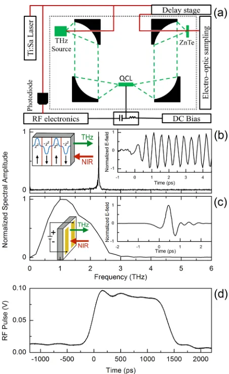
The experimental apparatus is shown in Fig. 1(a). The THz seed pulses are generated by pulsed femtosecond laser excitation of either an interdigitated photoconductive antenna on GaAs, for broad-band seed generation, or a PPLN crystal, for narrow-band seed generation. The fields
and spectra of a narrow-band THz seed and the broad-band THz seed are shown in Figs.1(b)and1(c), respectively. The reflection geometry is used for THz seed generation for both the photoconductive antenna25 and the PPLN crystal. In the case of the PPLN crystal two different THz waves are gener-ated in the forward and backward directions (with respect to the direction of the femtosecond pulse). The frequency of the forward (backward) generated wave is inversely proportional to the difference (sum) of the THz and optical group indices.22,23
The PPLN crystal has multiple periodically poled regions with periodicities ranging from 18.50 to 20.90lm in
increments of 0.30lm. The dimensions of the PPLN crystal
are 5100.5 mm and the dimension of each periodically poled region of the PPLN crystal is 5 0.50.5 mm. By moving the PPLN crystal with respect to the focused femto-second laser beam (approximately 0.3 mm), different peri-odically poled regions (and hence different THz seed frequencies) can be selected. The generated narrow-band THz frequencies range from 2.270 THz to 2.023 THz in steps of approximately 0.036 THz. Ideally, the bandwidth of the THz radiation generated in the PPLN is inversely propor-tional to the number of poling periods. However, THz absorption in the PPLN and variations in the length of the poling period will increase the bandwidth. In order to mini-mize absorption in lithium niobate, which can be significant at room temperature,26 the PPLN crystal is cooled to 10 K. The FWHM of the narrow-band seeds is on the order of 0.013 THz and is limited by absorption.
The THz QCL is a 3.25-mm-long and 0.15-mm-wide bound-to-continuum GaAs/AlGaAs laser processed as a sur-face plasmon waveguide.27 It has a threshold current of 100 A/cm2(at a two-terminal voltage of 3.3 V), and a maxi-mum operating temperature of 70 K. To ensure effective heat sinking, the device is indium bonded to a gold coated copper sub-mount.
In order to achieve injection seeding, before the arrival of the THz seed, a 2 W RF bias pulse, with a rise time of approximately 400 ps and duration on the order of 1.5 ns, is applied to the QCL as shown in Fig.1(d). To assist the nano-second bias pulse and ensure that the QCL is biased well above threshold, a quasi-DC bias is also applied to the QCL (two-terminal voltage: 1.5 V, current density: 45 A/cm2). A fast photodiode is used to generate the clock for the RF elec-tronics. This ensures that the repetition rate of the 1.5 ns bias pulse is synchronized to the 80 MHz repetition rate of the femtosecond laser and the THz seed pulses. The THz seed pulses are coupled into one of the QCL’s cleaved facets with 90 off-axis parabolic mirrors. The output pulses emitted from the opposite facet are measured in a free space electro-optic sampling arrangement with a 2-mm-thickh100iZnTe crystal.
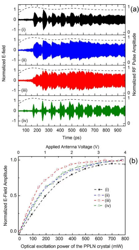
Injection seeding of the THz QCL is performed with a broad-band THz seed (Fig. 1(c)) from an interdigitated antenna in order to measure the frequencies of the longitudi-nal modes. The amplified waveform of the electric field is shown in Fig. 2(a-i). The first pass of the seed through the QCL occurs at time zero and is not shown in Fig.2(a). The THz pulse is injected into the QCL before the RF bias pulse is applied. As the THz seed pulse traverses the QCL, the FIG. 1. (a) Schematic of the experimental apparatus. Red lines are 80 fs
NIR-pulses with a center wavelength of 800 nm, an 80 MHz repetition rate, and an approximately 1W of average power. Green lines are the THz beam generated by the NIR-pulses. The dotted line is the purge box which pre-vents water vapor absorption of the THz beam. Both broad-band and narrow-band THz seed pulses are generated in a reflection geometry with respect to the femtosecond NIR beam. The THz seeds are coupled in to and out of the facets of the THz QCL with parabolic mirrors. A RF bias pulse, synchronized to the femtosecond laser repetition rate, drives the THz QCL above threshold. The THz fields are measured in an electro-optic setup with a 2 mm thick ZnTe crystal. (b) Spectra of a narrow-band THz seed pulse generated by optical rectification of the NIR pulses in the PPLN crystal. Insert: Electric field of the narrow-band seed versus time. (c) Spectra of the broad-band THz seed pulse generated by an interdigitated photoconductive antenna. Insert: Electric field of the broad-band seed versus time. (d) Voltage trace of the RF bias pulse recorded by an optical sampling oscillo-scope through a 50Xload with an attenuation of 40 dB.
[image:3.612.61.287.231.600.2]QCL is driven above threshold by the RF bias pulse. The RF bias pulse increases the gain above the losses in the cavity and enables large unclamped amplification.28As a result, the THz emission increases drastically after two round-trip times in the laser cavity. As the field increases in the laser cavity, stimulated emission of the upper laser level also increases. This decreases the population inversion and will eventually saturate the gain for a sufficiently high value of the inter-cavity electric field. In Fig.2(a), the maximum of the THz field amplitude is reached after three round-trip times at approximately 250 ps. The amplitude of the QCL emission is then nearly constant. However, small systematic variations of the QCL emission for all the THz waveforms are present. These variations arise from small ripples in the RF bias pulse in Fig.1(d)which are super-imposed as dashed lines on the data in Fig.2(a).
Any QCL emission arising from amplified spontaneous emission29 cannot be detected by electro-optic sampling of the THz field. Thus, it is important to verify that the QCL is indeed seeded by the injected THz pulses and not by ampli-fied spontaneous emission. Fig. 2(b) shows the QCL field amplitude at 246 ps as a function of either the near-infrared (NIR) pump power or the antenna bias voltage which are proportional to the narrow-band and broad-band seed ampli-tudes, respectively. When the output of the QCL is saturated by the THz seed, it indicates that the majority of the QCL emission arises from the THz seed amplification.
The time-resolved electric fields are directly Fourier transformed to obtain the spectral amplitude as shown in Fig.
3(a). The corresponding spectral amplitude of the broad-band seeded QCL is shown in Fig.3(a-i). As can be seen, the longitudinal modes consist of several frequencies between 2.173 THz and 2.274 THz, separated by a mode spacing of 0.013 THz. The main mode is centered at 2.223 THz, with two modes at 2.211 THz and 2.198 THz having approxi-mately half the spectral amplitude of the main mode. In addi-tion, a small mode at 2.236 THz and several satellite peaks are observed.
Figs.3(a-ii)–3(a-iv)show the spectra of the QCL when it is seeded with narrow-band THz pulses with center fre-quencies of (ii) 2.204 THz, (iii) 2.240 THz, and (iv) 2.270 THz. The normalized spectra of the narrow-band seed pulses (dashed lines) are superimposed on the corresponding spec-tra of the seeded QCL in Figs. 3(a-ii)–3(a-iv). The FWHM of the seed pulses is of the order of the longitudinal mode spacing. In Fig. 3(a-ii), the frequency of the narrow-band seed is at a lower frequency with respect to the main emis-sion mode observed with the broad-band seed. This causes the narrow-band seed to significantly suppress the main mode in Fig.3(a-i), while enhancing the side mode at 2.211 THz. On the other hand, when the frequency of the narrow-band seed is shifted to a higher frequency in Fig.3(a-iii), by selecting a different PPLN periodicity, the spectrum of the FIG. 2. (a) THz waveforms emitted by the QCL for (i) a broad-band seed
pulse from the interdigitated antenna, and for (ii)–(iv) narrow-band seed pulses from the PPLN crystal with frequencies of 2.204, 2.240, and 2.270 THz, respectively. The zero time corresponds to the first transmission of the seed pulse through the QCL. The black dashed lines are the trace of the RF bias pulse shown in Fig.1(d). (b) Maxima of the QCL field amplitudes in Fig.2(a) at 246 ps, as a function of the applied antenna voltage (for the broad-band seed) and the optical excitation power on the PPLN crystal (for the narrow-band seeds). The applied antenna voltage and the optical excita-tion power are proporexcita-tional to the seed amplitude. The femtosecond laser has a spot size of approximately 300lm.
[image:4.612.60.286.48.455.2]seeded QCL emission is also shifted to a higher frequency. The main peaks in Fig.3(a-ii)and in Fig. 3(a-i)are signifi-cantly suppressed by the seed in Fig.3(a-iii). In contrast, the higher frequency mode at 2.236 THz in Fig.3(a-iii)is dra-matically enhanced. Thus, the spectral emission of the QCL can be set by the seed frequency. In Fig.3(a-iv), the QCL is seeded with a narrow-band THz pulse whose frequency (2.270 THz) is on the high-frequency edge of the multi-mode emission in Fig.3(a-i). Although the satellite peaks at 2.261 and 2.274 THz in Fig.3(a-i)are significantly enhanced by the narrow-band seed in Fig.3(a-iv), the peak mode of the broad-band seeded emission (at 2.223 THz), has the highest spectral amplitude.
Single pass transmission of the broad-band THz pulse is used to measure the spectral gain of the QCL above thresh-old30 which is shown in Fig. 3(b). The maximum spectral gain occurs at a frequency of 2.222 THz which is nearly equal to the frequency of the main mode from the broad-band seeded emission in Fig. 3(a-i). The spectral region, where the narrow-band seeds can control the QCL emission in Figs. 3(a-ii) and 3(a-iii), is very close to the maximum spectral gain. Interestingly, the maximum spectral emission from the highest narrow-band seed frequency in Fig.3(a-iv)
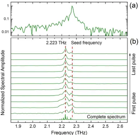
also occurs near the maximum of the spectral gain. This can be explained by noting that although the FWHM of the seed pulses are on the order of the longitudinal mode spacing, the wings of the narrow-band seed pulse extend across several longitudinal modes. This can be more clearly seen in the log-arithmic spectra of the narrow-band seed shown in Fig.4(a).
To investigate the dynamics of the narrow-band QCL seeded emission in Figs. 2(a-iv) and 3(a-iv), consecutive Fourier transforms are taken for each round-trip time, as shown in Fig. 4(b). The individual longitudinal modes are not visible since the resolution is equal to the mode spacing. The first spectrum corresponding to the second pass emitted
from the QCL at 77 ps has a global maximum near the seed frequency (2.274 THz) and a local maximum at the center frequency of the QCL emission spectra (2.223 THz). In con-trast, the second spectrum has a global maximum at the max-imum of the spectral gain while a local maxmax-imum near the seed frequency. For subsequent pulses, the ratio of the spec-tral amplitude at the narrow-band seed frequency decreases with respect to the spectral amplitude at the maximum spec-tral gain. Thus any residual specspec-tral components near the maximum of the gain will experience larger amplification than the spectral components (such as 2.274 THz) that are outside the maximum region of the spectral gain. Moreover, the evolution of the waveform in Fig. 2(a-iv) is also explained by the consecutive Fourier transform in Fig.4(b)
and the gain spectrum in Fig.3(b-iv). At earlier times, sev-eral amplified frequencies are in the cavity resulting in sig-nificant variations of the field amplitude and the formation of short pulses. Since the maximum of the gain is at signifi-cantly lower frequency than the seed in Fig. 3(b-iv), at later times the spectrum becomes narrower and only frequencies near the gain maximum are present.
The narrow-band THz seed pulses with frequencies ranging from 2.023 to 2.174 THz were not capable of satu-rating the gain in contrast to the narrow-band seeds shown in Figs.2(a)and3(a). This implies that a significant portion of the seeded QCL emission originates from amplified sponta-neous emission. However, the QCL emission from these seeds displayed similar behavior to the QCL emission from the 2.270 THz seed in that the strongest spectral components were always close to the maximum gain region.
In conclusion, a THz QCL was injection seeded with narrow-band THz seed pulses, generated with an optically excited PPLN crystal. Near the center of the QCL emission spectrum, seed pulses could be used to selectively enhance the QCL longitudinal mode closest to the seed frequency while suppressing the surrounding modes. Away from the center of the QCL emission spectrum, the seed pulses could be used to enhance the emission of satellite modes at the seed frequencies. However, in this case, they could not sup-press the main modes near the maximum of the spectral gain.
The authors acknowledge the support from: Referat 221 MIWF NRW, BMBF Q.com-H 16KIS0109, Mercur Pr-2013-0001, DFH/UFA CDFA-05-06, the Engineering and Physical Sciences Research Council (EPSRC), UK (COTS Program Nos. EP/J017671/1 and EP/J002356/1); the ERC (TOSCA); the Royal Society; and the Wolfson Foundation.
1
S. Fathololoumi, E. Dupont, C. W. I. Chan, Z. R. Wasilewski, S. R. Laframboise, D. Ban, A. Matyas, C. Jirauschek, Q. Hu, and H. C. Liu,
Opt. Express20, 3866 (2012). 2
L. H. Li, L. Chen, J. Zhu, J. Freeman, P. Dean, A. Valavanis, A. G. Davies, and E. H. Linfield,Electron. Lett.50, 309 (2014).
3H. Richter, M. Greiner-B €
ar, S. G. Pavlov, A. D. Semenov, M. Wienold, L. Schrottke, M. Giehler, R. Hey, H. T. Grahn, and H.-W. H€ubers, Opt. Express18, 10177 (2010).
4
M. Scheller, J. M. Yarborough, J. V. Moloney, M. Fallahi, M. Koch, and S. W. Koch,Opt. Express18, 27112 (2010).
5A. Scheuring, P. Dean, A. Valavanis, A. Stockhausen, P. Thoma, M. Salih,
S. P. Khanna, S. Chowdhury, J. D. Cooper, A. Grier, S. Wuensch, K. Il’in, FIG. 4. (a) Spectral amplitude of the 2.270 THz seed in Fig.2(b-iv)on a
log-arithmic scale. (b) Evolution of the QCL emission frequency as a function of the round-trip time for the 2.270 THz narrow-band seed. Each spectrum is obtained by applying a Fourier transform on each round-trip pulse within the waveform of Fig.2(a-iv). The rectangular window for each Fourier trans-form is 77 ps corresponding to the round-trip time in the QCL.
[image:5.612.62.287.485.704.2]E. H. Linfield, A. G. Davies, and M. Siegel,IEEE Trans. Sci. Technol.3, 172 (2013).
6
S. Fathololoumi, E. Dupont, D. Ban, M. Graf, S. R. Laframboise, Z. R. Wasilewski, and H. C. Liu,IEEE J. Quantum Electron.46, 396 (2010). 7S. Barbieri, J. Alton, C. Baker, T. Lo, H. E. Beere, and D. Ritchie,Opt.
Express13, 6497 (2005). 8
J. R. Gao, J. N. Hovenier, Z. Q. Yang, J. J. A. Baselmans, A. Baryshev, M. Hajenius, T. M. Klapwijk, A. J. L. Adam, T. O. Klaassen, B. S. Williams, S. Kumar, Q. Hu, and J. L. Reno,Appl. Phys. Lett.86, 244104 (2005). 9
A. Nahata, A. S. Weling, and T. F. Heinz, Appl. Phys. Lett.69, 2321 (1996).
10D. Oustinov, N. Jukam, R. Rungsawang, J. Mad
eo, S. Barbieri, P. Filloux, C. Sirtori, X. Marcadet, J. Tignon, and S. Dhillon,Nat. Commun.1, 69 (2010).
11
M. C. Beard, G. M. Turner, and C. A. Schmuttenmaer,J. Phys. Chem. B
106, 7146 (2002).
12A. Dreyhaupt, S. Winnerl, T. Dekorsy, and M. Helm,Appl. Phys. Lett.86,
121114 (2005). 13
J. R. Freeman, J. Maysonnave, H. E. Beere, D. A. Ritchie, J. Tignon, and S. S. Dhillon,Opt. Express21, 16162 (2013).
14J. Maysonnave, K. Maussang, J. R. Freeman, N. Jukam, J. Mad eo, P. Cavalie, R. Rungsawang, S. P. Khanna, E. H. Linfield, A. G. Davies, H. E. Beere, D. A. Ritchie, S. S. Dhillon, and J. Tignon,Opt. Express20, 20855 (2012).
15S. Bouchoule and J.-M. Lourtioz,Ann. Telecommun.49, 595 (1994). 16
Y. Ren, J. N. Hovenier, R. Higgins, J. R. Gao, T. M. Klapwijk, S. C. Shi, A. Bell, B. Klein, B. S. Williams, S. Kumar, Q. Hu, and J. L. Reno,Appl. Phys. Lett.97, 161105 (2010).
17M. S. Vitiello and A. Tredicucci,IEEE Trans. Terahertz Sci. Technol.1,
76 (2011).
18M. I. Amanti, M. Fischer, G. Scalari, M. Beck, and J. Faist,Nat. Photonics 3, 586 (2009).
19
O. P. Marshall, S. Chakraborty, Md. Khairuzzaman, T. Folland, A. Gholinia, H. E. Beere, and D. A. Ritchie,J. Appl. Phys.113, 203103 (2013). 20G. Xu, L. H. Li, N. Isac, Y. Halioua, A. G. Davies, E. H. Linfield, and R.
Colombelli,Appl. Phys. Lett.104, 091112 (2014). 21
Q. Qin, B. S. Williams, S. Kumar, J. L. Reno, and Q. Hu,Nat. Photonics
3, 732, (2009).
22Y.-S. Lee, T. Meade, V. Perlin, H. Winful, T. B. Norris, and A.
Galvanauskas,Appl. Phys. Lett.76, 2505 (2000). 23
Y.-S. Lee, T. Meade, M. DeCamp, T. B. Norris, and A. Galvanauskas,
Appl. Phys. Lett.77, 1244 (2000).
24J. A. L’huillier, G. Torosyan, M. Theuer, C. Rau, Y. Avetisyan, and R.
Beigang,Appl. Phys. B86, 197 (2007). 25
Y. C. Shen, P. C. Upadhya, E. H. Linfield, H. E. Beere, and A. G. Davies,
Appl. Phys. Lett.83, 3117 (2003). 26L. P
alfalvi, J. Hebling, J. Kuhl,A. P eter, and K. Polgar,J. Appl. Phys.97, 123505 (2005).
27
C. Worrall, J. Alton, M. Houghton, S. Barbieri, H. E. Beere, D. Ritchie, and C. Sirtori,Opt. Express14, 171 (2006).
28N. Jukam, S. S. Dhillon, D. Oustinov, J. Madeo, C. Manquest, S. Barbieri,
C. Sirtori, S. P. Khanna, E. H. Linfield, A. G. Davies, and J. Tignon,Nat. Photonics3, 715 (2009).
29J. Maysonnave, N. Jukam, M. S. M. Ibrahim, R. Rungsawang, K.
Maussang, J. Madeo, P. Cavalie, P. Dean, S. P. Khanna, D. P. Steenson, E. H. Linfield, A. G. Davies, S. S. Dhillon, and J. Tignon,Opt. Express20, 16662 (2012).
30N. Jukam, S. S. Dhillon, D. Oustinov, Z.-Y. Zhao, S. Hameau, J. Tignon,