Abstract: The approach of model-based user interface development (MBUID) paradigm is for building user interfaces using a set of models that take into account the various facets of a user interface at a semantic level. In this work model transformation of user interface has been explored from source model to target model using relational mapping and graphical notation. A framework based on mathematical graphical notation is presented and relational mapping to re-engineer declarative user interface model transformation through a platform independent model (PIM) is presented. For re-engineering user interface three steps; namely source code to platform specific source model (Extraction), platform specific source model to platform specific target model (Transformation) and platform specific target model to platform specific target code (Development) are followed. For achieving independence with respect to platform and language, user interface elements are addressed at the semantic level. A layer of abstraction of PIM has been added for defining few common basic user interface elements along with their attributes in semantic terms using mathematical graphical notation. Transformation has been defined between the source and target model and generic rules are applied for every new element extracted from source model and placed in the target model. By adding a new layer in the re-engineering process efforts required to port the user interface from one platform specific source model to one or more platform specific model are reduced. By defining the user interface elements semantically in graphical notation, diversity in the programming languages has been reduced. Bi-directionality has been achieved between the source model and the target model by defining the relational mapping between the two.
Keywords : Meta modeling, Model-to-model transformation, Relational mapping, Platform independent model
I. INTRODUCTION
Model transformation is a core technology that converts a source model to a target model which plays a significant role in model driven software re-engineering. It is described by a transformation definition which consists of a number of transformation rules and executed with the help of a transformational tool. A pre-requisite to model
Revised Manuscript Received on October 05, 2019. * Correspondence Author
Smita Agarwal*, Research Scholar, Department of Computer Science& Engineering, Mewar University, Chittorgarh (Raj), India Email: [email protected]
Alok Aggarwal, School of Computer Science, University of Petroleum & Energy Studies, Dehradun, India Email: [email protected]
S. Dixit, Department of Computer Science& Engineering, Mewar University, Chittorgarh (Raj), India Email: [email protected]
transformation is to build a precise meta-model which defines the structure and the rules of the language in which the models are expressed. Both the source model and target model can be on the same platform or can be on the different platforms. In case of platform specific modeling (PSM), the source model and target model are on the same platform while on different platforms for platform independent modeling (PIM). For example if a swing based desktop application is upgraded to new swing based user interface with some added new features and up gradations then it will be platform specific modeling while if the same application is upgraded to target android based user interface then platform independent modeling. Bi-directionality implies that the source model can be transformed to target model and target model can be transformed back to the source model. Many tools are available for bi-directionality between PSM to code generation but hardly any tool is providing bi-directionality between PIM to PSM. A true bidirectional transformation is difficult to achieve if neither new elements are added nor existing elements are modified. Only declarative model having information about the structure of user interface and ignoring the dynamic nature of the model can achieve bi-directional transformation. Very few tools are available that can achieve bi-directionality.
In this work model transformation of user interface has been explored from source model to target model using relational mapping and graphical notation. A framework based on mathematical graphical notation is presented and relational mapping to re-engineer declarative user interface model transformation through a platform independent model (PIM) is presented. For re-engineering user interface three steps; namely source code to platform specific source model (Extraction), platform specific source model to platform specific target model (Transformation) and platform specific target model to platform specific target code (Development) are followed. For achieving independence with respect to platform and language, user interface elements are addressed at the semantic level. A layer of abstraction of PIM has been added for defining few common basic user interface elements along with their attributes in semantic terms using mathematical graphical notation. Transformation has been defined between the source and target model and generic rules are applied for every new element extracted from source model and placed in the target
model.
Model Transformation of Declarative User
Interface from Platform Specific Model to
Platform Independent Model using Graphical
Notation.
Rest of the paper is organized as follows. In the next section, some of the major works done by earlier researchers in the said area are briefly analyzed. The section III gives the transformation tool. Mathematical approach for defining transformation is given in section 4. Finally, section 5 concludes the work.
II. LITERATUREREVIEW
In the development of software systems, Model Driven Engineering (MDE) is one of the promising methodologies in which model is the center of focus at different levels of abstraction [1]. In model-to-model transformation, one/multiple target model is automatically generated from one/multiple source model based on a transformation specification and is one of the important aspects of MDE paradigm [3]. A well-defined language, called Model Transformation Language (MTL) is used with appropriate syntax and semantics for specifying model-to-model transformations [2]. Declarative, imperative and hybrid are the three styles for model transformation languages [4]. Transformation approaches can be unidirectional and bidirectional [3]. The aim of bidirectional transformation approaches is to preserve the consistency between two or several models [5]. In [6], the authors have proposed a bidirectional transformation approach and later in [7] authors have combined it with traceability techniques to the Epsilon Validation Language (EVL), called EVL+trace. Different methods have been proposed to investigate transformation languages and their characteristics from different aspects [8]-[11]. In [18] authors have proposed a method in which programming language (PL) evaluation criteria have been used for the assessment of MTLs [12] and applied three major criteria and nine sub-criteria for MTL evaluation. Criteria is based on some PL evaluation criteria [13] and some bidirectional features [14]. Proposed criteria is studied on EVL+trace and three other well-known bidirectional
transformation approaches including
Query/View/Transformation-Relational (QVT-R) [15], Triple Graph Grammar (TGG) [16], and Janus Transformation Language (JTL) [17].
In [19] a model-driven approach, MAML, is proposed for mobile app development. Proposed approach focuses on a declarative and platform-agnostic DSL to graphically create mobile business apps. Advanced modeling support is provided by the visual editor component. Twenty six participants including software developers, process modelers, and domain experts confirmed the design goals of achieving a wide-spread comprehensibility of MAML models. Mobile app development can benefit to its full potential from the incorporation of people from all levels of the organization but current approaches often lack the capacity for holistic app modeling, often operating on a low level of abstraction with visual user interface builders or templates [20]-[21],[28]. Various approaches to cross-platform mobile app development have been researched that can be broadly categorized in five categories [22]. Like Apache Cordova [23] is a run time approach which provides a wrapper to web-based apps that allow for accessing device-specific features through interfaces and self-contained runtimes provide separate engines that mimic core system interfaces in which the app runs. J2ObjC [24] is used to transform Android-based business logic to Apple’s language
Objective-C, or model-driven software development for transforming a common model to code. Recently few companies have introduced new apps for this like Bizness Apps [25] and Bubble Group [26] aim for more holistic development approaches using configurators and web based editors. Similarly, graphical tools were provided for UI development, enhancing the programmatic specification of views by complementary drag and drop editors [29]. The WebRatio Mobile Platform [27] also supports codeless generation of mobile apps through a combination of IFML, other UML standards, and custom notations.
III. TRANSFORMATIONTOOL
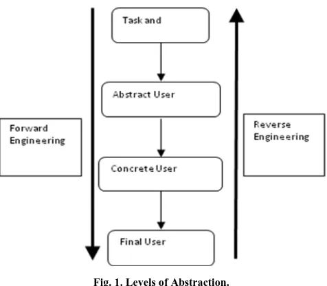
[image:2.595.309.547.495.703.2]The proposed transformation tool transforms from source PSM to abstract level PIM in first step. In the next step, it transforms to abstract level PIM to one or more target PSM. Although some tools do provide such feature to fulfill basic requirement of transforming source PSM to target PSM but there are no tools for providing bi-directionality feature on PSM to PIM level. The proposed XML and relational database based transformation tool for model driven software engineering for declarative user interface provide functionality for PSM to PIM Level. The tool not only relies on model driven architecture but also on XML and relational database. XML has been chosen since various contemporary programming languages have rich library to read and write XML file using DOM or SAX parser. The bi-directionality is achieved by mapping rules in database table and using SQL queries for creating, retrieving, updating or deleting mapping. The approach of model-based user interface development (MBUID) paradigm is for building user interfaces using a set of models that take into account the various facets of a user interface at a semantic level. The abstract representations of user interface are constructed that are transformed into concrete representations through an automated or semi-automatic process. Fig.1. shows the levels of abstraction.
Fig. 1. Levels of Abstraction.
Tasks and concepts describe the high level user tasks, the data and operations the application can support. The task models and domain models are used to represent these tasks and operations. Abstract User Interface (AUI) is the design of the arrangement and functionality
abstract specification may be context (user, platform and environment) and process independent. Concrete User Interface (CUI) is manifestation of AUI for a particular context. At this stage of abstraction, interaction control elements are identified and navigations are defined. This depiction is independent of any platform. Final User Interface is the final application that runs on a particular platform and is ready to be deployed. Many models have been defined for acquiring the different facets of a user interface.
IV. AMATHEMATICALAPPROACHFOR
DEFININGTRANSFORMATION
The standard way for describing modeling languages like UML, XML is meta-modeling. Meta-modeling helps to differentiate between the abstract syntax, concrete syntax and platform semantics. All three are defined using meta-modeling but the transformations between them require more refined approach. The mathematical relational approach is proposed using meta-modeling language to define the transformation. How meta-modeling can define the transformation between abstract syntax & concrete syntax and between abstract syntax & platform semantics, is exhibited in this section. A systematic approach of separating the components and their relationship among them is followed. The relationships among the components need not to be directional and a more generalized approach is used by making the approach bi-directional. Relationship among the components is defined to achieve the goal for a bi-directional approach. Example of editor of a model is presented in which input is the model and is viewed through either textual or diagrammatic syntax. The textual and diagrammatic syntax falls in the category of concrete syntax. The proposed model can be modified using abstract syntax. The tool should be capable of translating the modifications from one concrete syntax to abstract syntax and vice-versa thus achieving bi-directionality. Proposed approach is simplified by taking into account the mathematical model of the relation and encodes it as model object.
A. Mathematical Notation for extraction of elements In this sub-section, notation is given to formally define model transformation mapping from source meta-model to the target meta-model using graphical notation. The observed constraint is that the source model should be declarative and can be represented as graph. This allows to identify the similarities in the notation and to generalize them.
Model-to-model transformation mapping is one of the most intriguing problems for researchers. A mapping is defined as a rule to translate an element in the source model to the corresponding element in the target model, each model conforming to a particular meta-model. A mapping has following properties.
1. A mapping is complete if and only if it is defined for all elements in the model and conserves the relationship between them.
2. A mapping is direct if the source model and target model conform to same meta-model and indirect if they conform to different meta-models.
3. A mapping is uni-directional if the mapping is directed from source model to the target model and is bi-directional if the transformation can be applied from source to target and from target to source.
Notations are developed for the indirect bi-directional and
complete mapping. The user interface is described as a rooted and directed tree where the nodes of the tree represent the different elements in the UI. The widget or the control elements such as text box, button, check box, radio button etc. represent the node. Each node can have 0to n number of attributes representing the properties of the control elements. The dot notation is used to represent relation between the attribute and element. The expression used is UIElement.property = Value, for example Button.text= ―Reset.‖ The rules are defined in the following manner.
e Source Tree : e = elementX(e.attributeA != NULL e.parentNode=―elementY‖) AddNode (id, ―elementZ‖) This rule specifies that for any node e that belongs to the source tree such that it is equal to element X and either it has attribute A or its parent node is element Y, and then a node element Z is added to the target tree.
The syntax of these meta-models in XML is as follows. <model>
<modelname = "model name"/> <object>
id="Objid"
class="class in source library" <attlist>
<attribute>
<attbid> ….</attbid> <attbname> …..</attbname> <attbtype> …..</attbtype>
</attribute> .
. </attlist> <object/> . .
</model>
B. Defining UI Elements
Using the notations and operations for tree defined above, an example is taken for defining few UI Elements. The parameters of function are also defined.
1. Dialog Box –A dialog box is defined as having id, title,
isEnabled, and isVisible to the user and is shown in Fig. 2.
Fig. 2. Defining UI Element Dialog Box
2.Button - A button is defined as having id, text, icon,
isEnabled, isVisible to the user, having specified colour,
text written in specified font style and size and is shown in Fig. 3.
Fig. 3. Defining UI Element Button
3.CheckBox - A check box is defined as having id, text,
isSelected, isVisible to the user, having specified bounds x,
y, width and height and is shown in Fig.4.
Fig. 4. Defining UI Element Check Box
4.Audio - An audio elementis defined as having id, source,
file type and display controls and is shown in Fig.5.
Fig. 5. Defining UI Element Audio
5.Video - A video element is defined ashaving id, source, file type of specified height, width and display controls and is shown in Fig.6.
C. Defining Elements Mapping
In this sub-section, formation of rule is given to define the mapping between the element source tree and target tree. The source tree conforms to the source model and target tree conforms to the target model. The process of element mapping results in the target tree. Following steps are taken:
Initialization
In the first step, the root node for the target tree is created. The root contains the information about the XML version, encoding, platform-version, class and meta-model the tree conforms to. It is shown in Fig.7.
Fig. 7. Initialization
Defining Nodes of target tree
This process begins with the identification of a node in the source tree which leads to creation of node in the target tree. The corresponding node in the target tree is identified. The mappings for few UI Elements are given below.
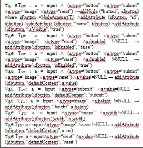
Button
[image:4.595.306.542.366.609.2]This first group of rules defines the extraction rules for Button. In the first rule, the button can be a normal button, submit button, reset button or an image button. The button is added to the tree and assigned id and is visible. In the second rule, the button is disables and isEnabled attribute is set to false. In the third rule, the button is enabled and isEnabled attribute is set to true. In the fourth rule, the value of button is set to a default value. In the fifth rule, the button is set to a submit button by default. In the sixth and seventh rule, the width and height of an image button is set. In the eight rule, the button is set to a reset button by default. These rules are shown in Fig.8.
Fig. 8. Rules for Button
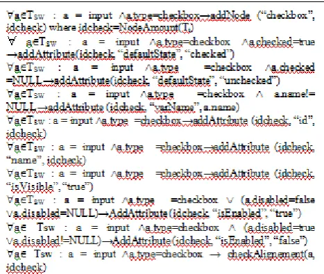
Check Box
In the first rule, the input is identified as the check box and is added to the node. In the second rule, the default state is identified as checked and in the third rule, the default state is identified as unchecked. The fourth rule identifies the name attribute of the check box. In the next two rules, the attributes
id and name are added. The check box is set to visible and is enabled in the next two. The next rule is used to disable the check box. The last rule is to check its alignment. These rules are shown in Fig. 9.
AddNode (text, idcheckBox)[ where idcheckBox = NodeAmount(Tt)] AddAttribute (idcheckBox, “isSelected”,false)AddAttribute (idcheckBox, “isEnabled”, “true”) AddAttribute (idcheckBox, “isVisible”, “true”) AddAttribute (idcheckBox, “text”, idcheckBox) Add Attribute (idcheckBox, “id”, idcheckBox) Add Attribute (idcheckBox, “boundX”, x) Add Attribute (idcheckBox, “boundY”, y) Add Attribute (idcheckBox, “boundWidth”, width) Add Attribute (idcheckBox, “boundHeight”, height)
AddNode (text, idvideo)[ where idvideo = NodeAmount(Tt)] AddAttribute (idvideo, ―source‖ source)AddAttribute (idvideo, ―fileType‖, type) AddAttribute (idvideo, ―text‖, idvideo) Add Attribute (idvideo, ―id‖, idvideo) Add Attribute (idvideo, ―hasControls‖, ―true‖) Add Attribute (idvideo, ―height‖, height) Add Attribute (idvideo, ―width‖, width)
Fig. 9. Rules for Checkbox
Audio
In this set of rules, an audio control is added to the t arget tree. The id, name and type of file (.wav, .mp3, etc) is identified and added to the node as attribute. The next two rules identifies whether or not the control of audio widget is to be displayed. The last two rules identify the default content of the widget. These rules are shown in Fig. 10.
Merging of two trees
The above rule is defined for merging of two trees. This can be translated into copying content of two different windows into a single window. In this operation, the merged tree is T0t and source trees are Tti. The source trees are emptied once the merged tree is obtained. Rule of merging two trees is shown in Fig. 11.
Defining the Alignment
In this step, the alignment of the widget appearing on the window is checked. The widget is represented as the
ElementID in the target tree. If the element has alignment
modifier (center, left, right) in the source tree then an attribute relating to the same is added to replicate the position in the target tree. It is shown in Fig. 12.
Fig. 12. Defining the Alignment Defining Generic Rules
The following generic rules are applied each time a new node is created. These rules check whether or not the element (node) from the source tree and set in the container (table, fieldset, datacell (td)) follows the same structure in the target tree. If not then the same structure is replicated for it.
Rule 1 - It verifies if the element a is in table and if no td, tr or
fieldset is nearer. If the table is the nearest node then an edge is added between the node b (abstraction of the node a in the target tree) and the node c (abstraction of the table in the target tree). It is shown in Fig.13.
Fig. 13. Generic Rule 1
Rule 2 - It verifies if the element a is in td and if no table, tror
fieldset is nearer. If the td is the nearest node then an edge is added between the node b (abstraction of the node a in the target tree) and the node c (abstraction of the td in the target tree). It is shown in Fig. 14. Similar rules are defined for fieldset and tr.
Rule 3 – It checks if the node x is not in the same path as a
table, td, tr, fieldset node. If it is the case, then an edge is added between the node b (abstraction of the node ain the target tree) and the node c (abstraction of the window in the target tree). It is shown in Fig. 15.
Fig. 15. Generic Rule 3
a Ts , ∃ b, c Tt : b = getAbstractNode (a) isInPath (a, table) (pathLength(table, a) <pathLength(tr, a)) (pathLength(table, a) <pathLength(fieldset, a)) (pathLength(table, a) <pathLength(td, a)) →c= getAbstractNode (NearestInPath(table,a)) addEdge(c,b) aTH : a = audio→addnode (―audio‖, idaudio) where idaudio
=NodeAmount(Tt)
aTH : a = audio → addAttribute (idaudio, ―id‖, id) aTH : a = audio → addAttribute (idaudio, ―name‖, name) aH : a = audio → addAttribute (idaudio, ―type‖, type)
aTH : a = audio → addAttribute (idaudio, ―hasControls‖, ―true‖) aTH : a = audio → addAttribute (idaudio, ―hasControls‖, ―false‖) aTH : a = audio x.expr != NULL → addAttribute (idaudio, ―defaultContent‖, a.expr)
aTH : a = audio x.src != NULL → addAttribute (idaudio, ―defaultContent‖, a.src)
a TS : IsInPath(center, a) → AddAttribute (elementId, ―Horizontal‖, ―center‖)
a TS: IsInPath(div.align=center, a) → AddAttribute (elementId, ―Horizontal‖, ―center‖)
a TS: IsInPath(div.align=right, a) → AddAttribute (elementId, ―Horizontal‖, ―right‖)
a TS: IsInPath(div.align=left, a) →AddAttribute (elementId, ―Horizontal‖, ―left‖)
a TS: a.align=left→AddAttribute (elementId, ―Horizontal‖, ―left‖) a TS: a.align =right→AddAttribute (elementId, ―Horizontal‖, ―right‖)
a TS: a.align =center→AddAttribute (elementId, ―Horizontal‖, ―center‖)
a TS: a.valign=bottom→AddAttribute (elementId, ―Vertical‖, ―bottom‖)
a TS: a.valign=top→AddAttribute (elementId, ―Vertical‖, ―top‖) a TS: a.valign=center→AddAttribute (elementId, ―Vertical‖, ―center‖)
a TS: IsInPath(div.valign= center, a)→AddAttribute (elementId, ―Horizontal‖, ―center‖)
a TS: IsInPath(div.valign=top,a)→AddAttribute (elementId, ―Horizontal‖, ―top‖)
a TS: IsInPath(div.valign=bottom, a)→AddAttribute(elelmentId, ―Horizontal‖, ―bottom‖)
a Ts , ∃ b, c, d Tt : b = getAbstractNode (a) getChildNodes (body ) c = getAbstractNode (body) d = table | d getChildNodes (c) getSiblingBefore (d) =NULL ->addEdge(d, b)
ato Ti
t , b T0t : a = window (b= container b=window) a.filename =b.targetfile → CloneNode(a.id, idnew, T0
t) where idnew =NodeAmount(T0t) RemoveNode(a, a.id) RemoveArc(ParentNode(a).id, a.id) c=root(Tit ) ٨Remove Node(c, c.id) ٨AddArc(b.id, idnew)
Fig. 10. Rules for Audio
a Ts , ∃ b, c Tt : b = getAbstractNode (a) isInPath (a, td) (pathLength(td, a) <pathLength(tr, a)) (pathLength(td, a) <pathLength(fieldset, a)) (pathLength(td, a) <pathLength(table, a)) →c= getAbstractNode (NearestInPath(td,a)) addEdge(c, b)
Fig. 14. Generic Rule 2
Implementation of Rules
All rules defined in the above sub-sections can be implemented by simple construct of if..else in the different programming languages. DOM structure can be used to parse the source files. The DOM libraries can parse, validate, serialize and manipulate XML. They implement all the functions such as createNode, createAttribute, deleteNodeetc, thus facilitating the implementation.
V. CONCLUSIONANDFUTURESCOPE
A framework has been defined in this work which is independent of the platform to address the diversity in programming languages using graphical notation and relational mapping. Uniform semi-formal mathematical notations have been used to define rules for extraction of UI elements and to define the relationship between the source and target model. PIM has been proposed between the source model and target model to reduce the efforts required for re-engineering. These rules are in the mathematical terms, simple, systematic, easily expressed& managed and most importantly independent of any kind of implementation. In future these rules can be expanded to include the various attributes and properties of the existing UI elements. More and more new elements and their mappings can be added to the existing list.
REFERENCES
1. Rieger, C. (2018). Evaluating a Graphical Model-Driven Approach to Codeless Business App Development. 51st Hawaii International Conference on System Sciences, (pp. 5725-5734)
2. Agarwal, S., & Agarwal, A. (2014). Model driven reverse engineering of user interface — A comparative study of static and dynamic model generation tools. International Conference on Parallel, Distributed and Grid Computing., (pp. 268 - 273).
3. T. Mens and P. Van Gorp, "A taxonomy of model transformation," Electronic Notes in Theoretical Computer Science, 152: 125-142, 2006.
4. S. Kolahdouz-Rahimi, A comparative study of model transformation approaches through a systematic procedural framework and goal question metrics paradigm. PhD diss., King's College London (University of London), 2013.
5. K. Czarnecki, J. Foster, Z. Hu, R. Lämmel, A. Schürr, and J. Terwilliger, ―Bidirectional Transformations: A Cross-Discipline Perspective,‖ in Theory and Practice of Model Transformations (R. Paige, ed.), vol. 5563 of Lecture Notes in Computer Science, pp. 260–283, Springer Berlin Heidelberg, 2009.
6. L. Samimi-Dehkordi, B. Zamani, and S. Kolahdouz-Rahimi, "From trace-based inter-model validation to bidirectional model synchronization with reconciliation," in the 5th International Conference on Computer and Knowledge Engineering (ICCKE 2015), pp. 123-130, 2015.
7. D. S. Kolovos, R. F. Paige and F. A.C. Polack, "On the Evolution of OCL for Capturing Structural Constraints in Modelling Languages," In Proc. Dagstuhl Workshop on Rigorous Methods for Software Construction and Analysis, 2007.
8. K. Czarnecki and S. Helsen. Feature-based survey of model transformation approaches. IBM Systems Journal, 45(3): 621-645, 2006.
9. R. Grønmo, B. Møller-Pedersen, and G.K. Olsen, "Comparison of three model transformation languages," In Model Driven ArchitectureFoundations and Applications, Springer Berlin Heidelberg, pp. 2-17, 2009.
10. M. V. Amstel, S.Bosems, I. Kurtev, and L. F. Pires, "Performance in model transformations: experiments with ATL and QVT," InTheory and Practice of Model Transformations, Springer Berlin Heidelberg, 2011, 198-212
11. K. Lano, S. Kolahdouz-Rahimi, and I. Poernomo, "Comparative evaluation of model transformation specification approaches,"
International Journal of Software and Informatics, 6(2): 233-269, 2012.
12. L. Samimi-Dehkordi, A. Khalilian, and B. Zamani, "Programming language criteria for model transformation evaluation," In the 4th International eConference on Computer and Knowledge Engineering (ICCKE 2014), IEEE, pp. 370-375, 2014.
13. R. W.Sebesta, Concepts of Programming Languages. 10th Ed., Pearson, 2012.
14. S. Hidaka, M. Tisi, J. Cabot, and Z. Hu, "Feature-based classification of bidirectional transformation approaches," Software & Systems Modeling, pp. 1–22, 2015.
15. OMG, "QVT. Meta Object Facility (MOF) 2.0 Query/View/Transformation 1.2 Beta Specification", 2015. 16. A. Schürr, and F. Klar, "15 years of triple graph grammars," In Graph
Transformations, Springer Berlin Heidelberg, pp. 411-425, 2008. 17. A. Cicchetti, D. Ruscio, R. Eramo, and A. Pierantonio, "JTL: A
Bidirectional and Change Propagating Transformation Language," in Software Language Engineering, vol. 6563, pp. 183–202, 2011. 18. Leila Samimi-Dehkordi, Bahman Zamani,
ShekoufehKolahdouz-Rahimi, ―Bidirectional Model Transformation Approaches: A Comparative Study,‖ 6th International Conference on Computer and Knowledge Engineering (ICCKE 2016), October 20-21, 2016.
19. Christoph Rieger, ―Evaluating a Graphical Model-Driven Approach to Codeless Business App Development,‖ Proc. 51st Hawaii International Conference on System Sciences, pp. 5725-5734, 2018.
20. Xamarin Inc., ―Developer center - Xamarin,‖ 2017. [Online]. Available: https://developer.xamarin.com
21. GoodBarber, ―Goodbarber: Make an app,‖ 2017. [Online]. Available: https://www.goodbarber.com/
22. T. A. Majchrzak, J. Ernsting, and H. Kuchen, ―Achieving business practicability of model-driven cross-platform apps,‖ OJIS, vol. 2, no. 2, pp. 3–14, 2015.
23. Apache Software Foundation, ―Apache Cordova documentation,‖ 2016. [Online]. Available: https://cordova.apache.org/docs/en/latest/ 24. Google Inc., ―J2ObjC,‖ 2019. [Online]. Available: http://j2objc.org/ 25. Bizness Apps, ―Mobile app maker — bizness apps,‖ 2019. [Online].
Available: http://biznessapps.com/
26. Bubble Group, ―Bubble - visual programming,‖ 2019. [Online]. Available: https://bubble.is/
27. WebRatio, ―WebRatio,‖ 2019. [Online]. Available: http://www.webratio. com/site/content/en/home
28. C. Rieger, ―Business apps with MAML: A model-driven approach to process-oriented mobile app development,‖ in Proceedings of the 32nd Annual ACM Symposium on Applied Computing, 2017, pp. 1599–1606.
29. Object Management Group, ―Unified modeling language,‖ 2019. [Online]. Available: http://www.omg.org/spec/UML/2.5
AUTHORSPROFILE
Smita Agarwal has earned Bachelor’s degree of Electronics & and Master’s degree of Information Technology in 1998 &2001 respectively from University of Delhi. She is currently pursuing Ph.D. in Computer Science & Engineering. She has seven years of industry experience and ten years in academic and research experience. She has contributed more than 10 research papers in different conferences and journals in the area of software engineering, m-learning and e-learning.