International Journal of Innovative Technology and Exploring Engineering (IJITEE) ISSN: 2278-3075, Volume-9 Issue-1, November 2019
Abstract— This article gives brief view of UWB microstrip antenna characteristic without a slot and with a triangular slot on the patch of the MSA. Nowadays UWB antenna is a must for wireless communication with the narrow pulses in the series of nanoseconds, for the application of ultra- wideband in frequency domain for very short distance and minimum power densities. The research in this field has become more sought-after and therefore the demand on UWB microstrip antenna is rising rapidly. The currents along the verge of the slot initiates additional resonance, it concords with the main patch resonance, which result in the production of overall frequency response characteristics, ultimately leads to wideband. Thus a crisp novel ultra-wideband configuration with and without a triangular slot have been proposed. And the radiation is in the broadside of antenna with small variation along the entire bandwidth. Thus improving the robustness of the MSA and cost reduction. Due to the potential of UWB antennas,they are significant to improve the performance of wireless communication systems. The MSA (microstrip antenna) is designed with FR-4 substrate. There is increase in bandwidth due to the introduction of triangular slot in the patch and the variation in the antenna parameters are briefed below. This document can be used as guide to design small MSA for mobile communication.
Keywords— MSA, return loss, slot, UWB, bandwidth
I. INTRODUCTION
Microstrip antennas are extensively used owing to their low profile, conformal, light weight and ease of fabrication. While they are generally designed for linear polarization, circularly polarized antennas have captivated much awareness in recent years. These antennas are significant due to their ability to improve the performance of wireless communication systems. Due to the attractive advantage of high speed data rate ,UWB communication system gains enormous attention. The mobile communication has increased urges on the UWB system and eventually to energize the research activities in different UltraWideBand antenna design. One of the key aspect of the forefront and mobile communication technology is the design of conformal,compact and low cost antennas. The major drawback is narrow bandwidth, poor efficiency size. The initial UWB system were designed for the U.S military and
Revised Manuscript Received on July 22, 2019.
J. Joselin Jeya Sheela , Electronics and Communiction Engineering, R.M.K. Engineering College, Chennai, India. Email: joselinmoses @gmail.com
S. Rosaline , Electronics and Communiction Engineering,R.M.K. Engineering College, Chennai, India. Email: [email protected]
M. Aswini , Electronics and Communiction Engineering,R.M.K. Engineering College, Chennai, India. Email: [email protected]
V. Praveen Kumar ,Nagman instrumentation & Electronics Private Limited , Chennai,India. Email :[email protected]
[image:1.595.305.549.266.425.2]other government wings, .i.e. to convert radar and communication equipments. These days the development in the chip has made UWB reliable for commercial and civilian purpose [3]. This supports more data transfer rate for streaming video and audio, and enables high data transfer rate with very less power consumption. In 1980’s UWB was known as impulse or base- band technology.
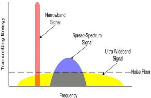
Fig. 1 Bandwidth Classification
Before 1990, the UWB antennas were based on volumetric and less on planar structures. The basic UWB antenna roots to 1939. Carter is the person who investigated biconical and conical monopole antenna with a tapered feed [9] in 1941 Stratton and Chu proposed spheroidal antenna. U.S radio research laboratory staff proposed wideband antenna. The UWB antenna and conventional antenna are compared [1]. The dipole antenna are not befitting for UWB application. Whereas, a non-resonant antenna covers a wide frequency range. Thus a compact novel wideband configuration consisting of triangular slot on the patch is implemented. The radiation pattern of a triangular microstrip antenna are along the broadside of the antenna with a slight variation over the complete bandwidth. This antenna has outspread half power beam width making it acceptable for the largescale examine broadband antenna array. The robustness of the antenna is improved . The analysis of slotted and slot less microstrip antennas are given.
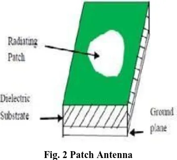
II.MICROSTRIP PATCH ANTENNA In common the microstrip antenna consist of a patch which radiates as shown in Fig.2, this patch can either be non-planar or in geometry present on the one side of the substrate on the rear side with ground plane.
Triangular UWB Antenna with Reduced Ground
Plane Effect
This MSA is also known as ‘printed resonant antenna’ and they are used for narrow-band microwave wireless links where semi-hemispherical coverage is required.
[image:2.595.81.260.142.304.2]Because of the low profile and ease of fabrication, great number of microstrip antennas are studied. The rectangular and circular MSA’s are the basic and commonly used MSA. The evaluation and fruition prediction are
Fig. 2 Patch Antenna
simplified by using various patch shapes such as square, circular, triangular or some other common shape.
Microstrip patch antennas radiate due to the fringing fields linking the ground plane and patch. A thick dielectric substrate having a low dielectric constant is desirable for better antenna performance since it provides good efficiency, wide bandwidth and better radiation characteristics. Moreover, such configuration lead the way to a large sized antenna . Substrates with high dielectric constants are required to model a compact MSA with less efficiency and results in a narrow bandwidth. Hence a crossfire must be accomplished between the dimensions and performance of antenna .
The upsides of MSAs make them appropriate for several applications. The communication and telemetry antennas on missiles ought to be thin and conformal . Radar altimeters employ arrays of microstrip antenna. Aircraft oriented applications incorporate antennas for satellite and telephone communication. Ultra wideband microstrip antenna have been intended for microwave imaging systems. Micropatch antennas have been used in ships and satellites over communication links . Smart weapon system also employ MSA because of their low profile. Pagers, the global system for mobile communication and the global positioning systems are major users of MSA.
III.ULTRAWIDEBAND ANTENNA
Since February 14, 2002, the ultrawideband technology have become the most flourishing and guaranteed wireless communication technologies which persuades to revolutionize high data rate transmission, thus enabling the personal area networking industry developing innovations and with greater service quality to the end users.
Large transmission bandwidth, which ranges from near direct current (dc) to a few GHz, it has a resultant higher immunity to interference and good multipath fading robustness. The
Eventhough, the lower frequencies have better penetration properties across various materials, thus increases the UWB radio coverage.
The UWB radio operates using extremely large bandwidths and co-exist with the other interfering narrow band systems. Simultaneously these narrow band systems should not suffer from unbearable interference from the UWB radio. Consideration of regulations over the wider bandwidth limits the radiated power. The complexity of the receiver and the synchronisation acquisition time can be increased significantly by the lower transmission power levels. As the UWB being the top technology for delivering people from the usage of wires, offering wireless connectivity for multiple devices enabling the transmission of video, audio as well as high bandwidth data. It is designed for short range, used to relay the data from a host device to another devices in the nearby area .i.e. within 10m or 30feet.
In the previous years, there has been a rapid developmental experiments on the technology using UWB signals. Thus the major enhancements in the wireless application areas such as communication, radar positioning or ranging are offered by the UWB technology. This UWB technology also can be delivered over wired lines and cables eg. Cable television [2]. Ever since the antenna plays a captious title role in the UWB communication system. The way out of a specific UWB antenna design must be build on the requirements of the application. In the proposed antenna design the various geometries and perturbation techniques of planar monopole antenna are applied.
IV.DESIGN OF RECTANGULAR MSA Initially a rectangular patch antenna is designed. That is MSA with a dielectric substrate of height 'h', relative dielectric constant εr and antenna operating frequency fr. The efficient width of the patch and length of the patch can be calculated by,
W = c/2f [(∈r + 1) /2] -1/2 and L = c / 2f √∈e − 2Δl [1]
Where, ∈e and Δl can be calculated from [8].
A. Triangular MSA Design
The rectangular patch of width 16mm and length of 12mm is cut into a triangular MSA using the tools in the simulator. An isosceles triangular microstrip antenna is obtained. Thus a triangular patch with minimum size is formed. Only one port is used for simulation
B.MICROSTRIP LINE FEED
International Journal of Innovative Technology and Exploring Engineering (IJITEE) ISSN: 2278-3075, Volume-9 Issue-1, November 2019
V.SIMULATION RESULT A.Without Slot in the Patch
[image:3.595.311.547.52.255.2]The representation of triangular MSA with dielectric substrate made of FR-4 material is shown in Fig. 2
Fig. 2 Front view of triangular MSA
Fig.3 Ground plane of MSA
Characteristics
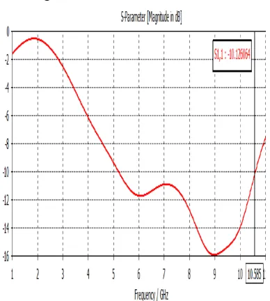
The various parameters such as VSWR, radiation pattern especially the impedance bandwidth is represented here.
The UWB ranges from 5.2GHZ to 10.1GHZ.
[image:3.595.311.548.79.455.2]Fig. 4 Return loss of without slot MSA
[image:3.595.81.258.98.449.2]Fig. 5 VSWR plot of without slot MSA
Fig. 6 Radiation Pattern of without slot MSA B.With slot in the patch
The representation of triangular MSA with slot within patch made of dielectric substrate FR-4 material is shown in Fig.
[image:3.595.341.513.518.677.2] [image:3.595.72.266.521.737.2]Fig. 8 Back view of triangular MSA with slot on the ground plane
Characteristics
[image:4.595.312.548.65.244.2]The various parameters such as VSWR, radiation pattern especially the impedance bandwidth is represented here.
Fig. 9 Return loss of with slot MSA
Fig. 10 VSWR plot of with slot MSA
Fig. 11 Radiation Pattern of with slot MSA The UWB ranges from 5.2GHZ to 10.4GHZ. Thus the parameters are improved.
VI.CONCLUSIONS
Thus the complete analysis of the patch antenna with and without slot within the patch is done in this paper. Through the scrutiny it was put in place that characteristics of MSA with slot on the ground plane is much better than the one without slot. Clear analysis done in this paper for return loss, VSWR and other parameters and the bandwidth is increased. Thus there is variation in bandwidth and other parameters are improved.
REFERENCES
1. Ali Araghi and Gholamreza Dadashzadeh (2012) ‘Oriented design of an antenna for MIMO Applications using Theory of characteristic modes’IEEE antennas and wireless propagation letters, Vol 11.pp1040-1043.
2. Debatosh Guha and Jawad Y.Siddiqui (2004) ‘Resonant Frequency of equilateral triangular Microstrip antenna with and without air gap’, IEEE transactions on antennas and propagation,Vol. 52, No.8,pp.174-2177.
3. Iti Saha Misra and Chowdary.S.K(1998)’Study of Impedence and Radiation Properties of a Concentric Microstrip Triangular-Ring Antenna and its Modelling Techniques Using FDTD Method’,IEEE transactions on antennas and propagation,Vol. 46,No. 4,pp.531-537. 4. Jeen-Sheen Row and Yen-Yu Liou (2006) ‘Broadband Short-Circuited Triangular Patch Antenna’,IEEE transactions on antennas and propagation, Vol. 54,No.7,pp.237-2141.
5. Jieh-Sen Kuo and Gui-bin Hsieh (2003) ‘Gain Enhancement of a Circularly Polarized Equilateral- Triangular Microstrip Antenna with a slotted ground plane’IEEE transactions on antennas and propagation,Vol. 51, No.7,pp.1652-1656.
6. Jui-han Lu,Chia-Luan Tang and Kin-Lu Wong(2000) ‘Novel Dual-Frequency and Broad-Band Designs of Slot-Loaded Equilateral Triangular Microstrip Antennas’,IEEE transactions on antennas and propagation, Vol.48,No.7,pp.1048-1054.
7. Jui-han Lu,Chia-Luan Tang,and Ki-lu Wong(1999) ‘Single-Feed Slotted Equilateral-Triangular Microstrip Antenna for Circular Polarization’,IEEE transactions on antennas and propagation, Vol.47,No.7,pp.1174-1178.
8. Jui-Han Lu and Kin-Lu Wong (2000) ‘Single-Feed Circularly Polarized Equilateral-Triangular Microstrip Antenna with a Tuning Stub’ IEEE transactions on antennas and propagation, Vol.48, No.12, pp.1869-1872.
[image:4.595.56.284.332.704.2]International Journal of Innovative Technology and Exploring Engineering (IJITEE) ISSN: 2278-3075, Volume-9 Issue-1, November 2019
10. Lin,Y.-C. Kuo and H-R .Chuang (2005) ‘A Planar Triangular Monopole Antenna for UWB Communication’,IEEE microwave and wireless components,Vol.15,No.10,pp.624-626.
AUTHORSPROFILE
J.JOSELIN JEYA SHEELA, received her Bachelor’s degree in Electronics and communication Engineering from Anna University in the year 2005 and Master’s degree in Communication system from Anna University in the year 2009, she is currently an Assistant Professor in the Department of Electronics and Communication Engineering, R.M.K Engineering College, affiliated to Anna University, Chennai. Her area of interests and research domain are RF and Antennas. She has published book on ‘RF and Microwave Engineering’ for the benefit of VII semester ECE students.
S.ROSALINE, received her Bachelor’s degree in Electronics and communication engineering from Anna University in the year 2005 and Master’s degree in VLSI Design from Anna University in the year 2008, she is currently an Assistant Professor in the Department of Electronics and Communication Engineering, R.M.K Engineering College, affiliated to Anna University, Chennai. Her area of interests are VLSI Design,Antennas and Embedded Systems.
M. Aswini, received her bachelor’s degree in Electronics and Communication Engineering from Anna University in the year 2006 and Master’s Degree in Communication Systems from Anna University in the year 2008.She is currently an Assistant professor in the department of Electronics and Communication Engineering ,R.M.K. Engineering College affiliated to Anna University Chennai. Her area of interest are RF and Antennas.