Abstract: This paper addresses the behaviour of multi storey structure considering soil structure interaction i.e. interaction between substructure of the building and soil. For this purpose a sample of 5 storey RC frames is analysed in conventional method with incremental static analysis for various load combinations and determines the parameters displacement, shear force and bending moment. Then a same 5 storey RC frame is analysed in numerical analysis using Finite Element Method (FEM) with raft foundation by assigning the soil properties to substructure and determine the parameters displacement, shear force and bending moment. According to the analysis results the parameters displacements, shear force and bending moment varies from conventional analysis to numerical analysis. Displacements of the structure increases, shear forces of the structure decreases and bending moment of the structure decreases at some points and increases at some points from conventional method of analysis to numerical method of analysis.
Keywords : Soil Structure interaction, Conventional Method of Analysis, Numerical Method of Analysis, Displacement, Shear Force, Bending Moment..
I. INTRODUCTION
The process in which the response of the soil influences the motion of the structure and the motion of the structure influences the response of the soil is termed as soil-structure interaction (SSI).Conventional structural design methods neglect the SSI effects. Investigations of soil structure interaction have shown that the dynamic response of a structure supported on flexible soil may differ significantly from response of the same structure when supported on rigid base. One of the significant purposes behind this distinction is that piece of the vibrational vitality of adaptable mounted structure is disseminated by radiation of stress waves in the supporting medium and by hysteretic activity in the medium itself. Expository techniques to figure the dynamic soil-structure communication impacts are settled. At the point when there is more than one structure in the medium, in light of obstruction of the basic reactions through the dirt, the dirt structure reactions through the dirt, soil structure issue
Revised Manuscript Received on November 05, 2019.
KORRAPATI PRATYUSHA, Department of Civil Engineering, Narasaraopeta Engineering College [Autonomous], Narasaraopet, India.
DOREDLA NAGARAJU, Department of Civil Engineering, Narasaraopeta Engineering College [Autonomous], Narasaraopet, India.E-mail:[email protected]
K DINESH KUMAR, Department of Civil Engineering, Narasaraopeta Engineering College [Autonomous], Narasaraopet, India. Department of Civil Engineering, Narasaraopeta Engineering College [Autonomous], Narasaraopet, India.
develops to a cross connection issue between different structures. It has expectedly been viewed as that dirt structure communication beneficially affects the seismic reaction of a structure. Many plan codes have recommended that the impact of SSI can sensibly be dismissed for the seismic investigation of structures. This legend about SSI clearly comes from the bogus observation that SSI decreases the by and large seismic reaction of a structure, and subsequently, prompts improved security edges. A large portion of the plan codes use distorted structure spectra, which accomplish consistent quickening up to a specific period, and from that point diminishes monotonically with period. Considering soil-structure communication makes a structure progressively adaptable and in this manner, expanding the characteristic time of the structure contrasted with the comparing inflexibly bolstered structure. Additionally, considering the SSI impact builds the successful damping proportion of the framework. The smooth romanticizing of structure range proposes littler seismic reaction with the expanded common time frames and successful damping proportion due to SSI. With this presumption, it was generally been viewed as that SSI can advantageously be ignored for preservationist plan. Moreover, dismissing SSI massively lessens the difficulty in the examination of the structures which has enticed originators to disregard the impact of SSI in the investigation.
This moderate improvement is substantial for certain class of structures and soil conditions, for example, light structures in generally firm soil. Sadly, the suspicion doesn't generally remain constant. In fact, the SSI can have a detrimental effect on the structural response, and neglecting SSI in the analysis may lead to unsafe design for both the superstructure and the foundation.
In this paper a 5 storey reinforced concrete frame is analysed and designed as per IS 456:2000 in conventional method with different load combinations and determine the parameters displacements, shear force and bending moment by keeping the base as fixed. From the reactions obtained in conventional methods for the RC frame, raft foundation is designed. Similarly a same 5 storey reinforced concrete frame is analysed in Numerical method based on finite element method with raft foundation at the base by assigning soil properties to the substructure and determine the parameters displacements, shear forces, bending moment. Comparison of parameters displacements, shear forces and bending moments for both models is done i.e. with SSI and without SSI.
Effect of Soil Structure Interaction on
Multi-Storeyed Building with Raft Foundation
Effect of Soil Structure Interaction on Multi-Storeyed Building with Raft Foundation
II. METHODOLOGY
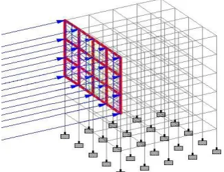
[image:2.595.324.556.49.274.2]A symmetrical 5 storey building is modeled using STAAD Pro software package with 4 no of bays in X direction and 4 no of bays in Z direction. The span of the columns is 3m in X direction and 3m in Z direction. The plinth area of the building is 12m x 12m. The total height of the 5 storey building is considered as 15m. The height of each storey is taken as 3m respectively.
[image:2.595.71.543.140.808.2]Fig 1 Plan view of the structure
Fig 2 Isometric view of the structure 2.1. Model data of the Structure:
Table 1 Structural Properties of the Structure Structural Properties
Structure OMRF
No of Storeys 5
Storey Height 3.00 m
Type of building used Residential
Foundation Type Raft Foundation
Seismic Zone III
Material Properties
Grade of concrete used M 30
Grade of steel used 415 MPA
Young’s Modulus of
Concrete 27.38 x 10
6 KN/m2
Density of Reinforcement
Concrete 25 KN/m
3
Modulus of Elasticity of
brick masonry 3.50 x 10
6 KN/m3
Density of brick masonry 19.2 KN/m3
Member Properties
Thickness of Slab 0.125 m
Beam size 0.45 x 0.23 m
Column size 0.45 x 0.45 m
Thickness of outer wall 0.230 m
Thickness of inner wall 0.115 m
Seismic Parameters
City Vijayawada
Zone III
Response Reduction Factor 3
Structure type RC Framed building
Damping Ratio 5%
Soil Properties
Type of soil Loose Sand
Soil Bearing Capacity 215 KN/m2
Codes
RCC Design IS 456:2000
Seismic Design IS 1893 Part 4
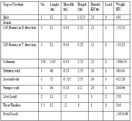
2.2 Calculations of loads:
2.2.1 Dead loads and Live loads of the building: The dead load of the building includes the self-weight, wall load (outer
walls and inner walls), floor load and parapet wall load.
Table 2 Load calculations
2.2.2 Wind load: From IS 875 (Part III)
Design Wind Pressure (Pz) = 0.6 Vz2
Where Pz = design wind pressure in N/ms at height z, and Vz = design wind velocity in m/s at height z. Design Wind Speed (Vz) = Vb x k1 x k2 x k3 Where Vb = basic wind speed
[Vb = 55m/s, Vb = 50m/s, Vb = 47m/s and Vb =39m/s] k1= probability factor (Table 1 clause5.3.1)
k2 = height and structure size factor (Table 2 clause 5.3.2) k3 = topography factor (Table 2 clause 5.3.3)
[image:2.595.62.286.165.452.2] [image:2.595.319.541.382.586.2]Vz = 55 x 1 x 1.1 x 1 = 60.5 m/s; Pz = 0.6 Vz2 = 2.196 KN/m2 Vz = 50 x 1 x 1.1 x 1 = 55.0 m/s; Pz = 0.6 Vz2 = 1.815 KN/m2 Vz = 47 x 1 x 1.1 x 1 = 51.7 m/s; Pz = 0.6 Vz
2
= 1.603 KN/m2 Vz = 39 x 1 x 1.1 x 1 = 42.9 m/s; Pz = 0.6 Vz2 = 1.104 KN/m2
2.2.3 Earthquake load parameters: For Zone III
Structure type = RC framed building Response reduction factor (RF) = 3 Importance Factor (I) = 1
Zone Factor = 0.16 Damping ratio (DM) = 5%
2.2.4 Base Shear Calculation: Zone factor for zone III = 0.16 Importance factor = 1.5 Response factor = 3
Intensity of dead load = 16.8 KN/m3 Imposed load:
Floor load = slab thickness x density of concrete = 0.125 x 25
= 3.125 KN/m3 Liveload = 2 KN/m3 Dust load = 0.5 KN/m3
Imposed load = Floor load + live load +Dust Load = 3.125 + 2+ 0.5
= 5.625 KN/m3
Total floor area = 12m x 12m = 144 m2
Load on one floor = 144 (16.8 + 0.25 x 5.625) = 2621.7 KN Load on roof = 144 x 16.8 = 2419.2 KN
Total load on structure (W) = 5 x 2621.7 + 2419.2 = 15527.7 KN
Base shear (Vb) = AhW
Ah = (ZIS/2RG) = (0.16 x1.5 x 2.5)/ (2 x 3) = 0.1 Base shear (Vb) = 0.1 x 15527.7 = 1552.7 KN
Vertical distribution of base shear: 5th Floor:
Q5 = (W1h1 2/ Σ W
ihi 2
)
= (2419.2 x 182)/ ((2419.2 x 182) (2621.7 x 152) (2621.7 x 122) (2621.7 x 92) (2621.7 x 62) (2621.7 x 32))
Q5 = 0.37 4th Floor: Q4 = (W2h2
2/ Σ W ihi
2 )
= (2621.7 x 152)/ ((2419.2 x 182) (2621.7 x 152) (2621.7 x 122) (2621.7 x 92) (2621.7 x 62) (2621.7 x 32))
Q4 = 0.28 3rd Floor: Q3 = (W3h3
2/ Σ W ihi
2 )
= (2621.7 x 122)/ ((2419.2 x 182) (2621.7 x 152) (2621.7 x 122)(2621.7 x 92) (2621.7 x 62) (2621.7 x 32))
Q3 = 0.18 2nd Floor:
Q2 = (W4h42/ Σ Wihi2)
= (2621.7 x 92)/ ((2419.2 x 182) (2621.7 x 152) (2621.7 x 122) (2621.7 x 92) (2621.7 x 62) (2621.7 x 32))
Q2 = 0.10 1st Floor:
Q1 = (W1h12/ Σ Wihi2)
= (2621.7 x 62)/ ((2419.2 x 182) (2621.7 x 152) (2621.7 x 122) (2621.7 x 92) (2621.7 x 62) (2621.7 x 32))
Q1 = 0.045 Ground Level: Qgl = (Wglh12/ Σ Wihi2)
= (2621.7 x 32)/ ((2419.2 x 182) (2621.7 x 152) (2621.7 x 122) (2621.7 x 92) (2621.7 x 62) (2621.7 x 32))
[image:3.595.300.555.98.402.2]Qgl = 0.011
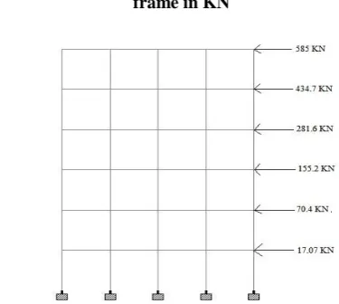
Table 3 Design lateral loads at each floor
Level Wi
(KN) hi (m)
(W1h12/ΣWihi2) Lateral Force (KN)
5th Floor 1552.7 18 0.37 585
4th Floor 1552.7 15 0.28 434.7
3rd Floor 1552.7 12 0.18 281.6
2nd Floor 1552.7 9 0.10 155.2
1st Floor 1552.7 6 0.045 70.4
Ground Level
1552.7 3 0.011 17.07
[image:3.595.326.514.401.569.2]Fig 3 Equivalent static lateral load (sway to right) on frame in KN
Fig 4 Equivalent static lateral load (sway to left) on frame in KN
2.2.5 Load Combinations:
The load combinations given in the analysis according to
relevant IS codes of practice (IS 1893-2002 and IS 875 Part
III-1987)
Effect of Soil Structure Interaction on Multi-Storeyed Building with Raft Foundation
[image:4.595.73.522.35.740.2] 0.9 DL ± 1.5WLz 1.2 (DL+LL± WLx) 1.2 (DL+LL± WLZ) 1.5(DL ± ELx) 1.5(DL ± ELz) 0.9 DL ± 1.5 ELx 0.9 DL ± 1.5ELz 1.2 (DL+LL± ELx) 1.2 (DL+LL± ELZ)
Fig 5 Dead Load Diagram
Fig 6 Live load Diagram
[image:4.595.352.496.48.193.2]Fig 7 Earthquake Load in X Direction
[image:4.595.361.506.233.364.2]Fig 8 Earthquake Load in Z Direction
Fig 9 Earthquake Load in -Z Direction
[image:4.595.342.505.398.523.2]Fig 10 Wind Load in X Direction
[image:4.595.342.515.536.703.2]Fig 12 Wind Load in Z Direction
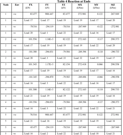
2.2.6 Reaction at Ends:
Table 4 Reaction at Ends
Node Env FX FY FZ MX MY MZ
(kN) (kN) (kN) (kNm) (kNm) (kNm)
1 +ve 83.477 988.447 83.477 272.981 0.122 267.949
1 +ve Load: 17 Load: 17 Load: 19 Load: 19 Load: 17 Load: 20
1 -ve -78.516 -294.119 -78.516 -267.949 -0.122 -272.981
1 -ve Load: 20 Load: 1 Load: 22 Load: 22 Load: 16 Load: 17
2 +ve 101.556 1.16E+3 82.122 272.163 0.117 290.373
2 +ve Load: 17 Load: 19 Load: 19 Load: 19 Load: 22 Load: 20
2 -ve -101.300 -296.031 -79.504 -269.396 -0.118 -290.733
2 -ve Load: 20 Load: 3 Load: 22 Load: 22 Load: 19 Load: 17
3 +ve 101.345 1.17E+3 82.154 272.418 0.066 290.558
3 +ve Load: 17 Load: 19 Load: 19 Load: 19 Load: 17 Load: 16
3 -ve -101.345 -296.870 -79.583 -269.696 -0.066 -290.558
3 -ve Load: 16 Load: 3 Load: 22 Load: 22 Load: 16 Load: 17
4 +ve 101.300 1.16E+3 82.122 272.163 0.118 290.733
4 +ve Load: 21 Load: 19 Load: 19 Load: 19 Load: 19 Load: 16
4 -ve -101.556 -296.031 -79.504 -269.396 -0.117 -290.373
4 -ve Load: 16 Load: 3 Load: 22 Load: 22 Load: 22 Load: 21
5 +ve 78.516 988.447 83.477 272.981 0.122 272.981
5 +ve Load: 21 Load: 16 Load: 19 Load: 19 Load: 19 Load: 16
5 -ve -83.477 -294.119 -78.516 -267.949 -0.122 -267.949
[image:5.595.59.457.280.715.2]
Effect of Soil Structure Interaction on Multi-Storeyed Building with Raft Foundation
36 +ve 82.122 1.16E+3 101.556 290.733 0.118 269.396
36 +ve Load: 17 Load: 17 Load: 19 Load: 19 Load: 17 Load: 20
36 -ve -79.504 -296.031 -101.300 -290.373 -0.117 -272.163
36 -ve Load: 20 Load: 1 Load: 22 Load: 22 Load: 20 Load: 17
37 +ve 101.720 974.958 101.720 291.383 0.076 291.016
37 +ve Load: 17 Load: 11 Load: 19 Load: 19 Load: 17 Load: 20
37 -ve -101.458 -0.697 -101.458 -291.016 -0.076 -291.383
37 -ve Load: 20 Load: 1 Load: 22 Load: 22 Load: 16 Load: 17
38 +ve 101.506 980.936 101.806 291.690 0.079 291.204
38 +ve Load: 17 Load: 11 Load: 19 Load: 19 Load: 17 Load: 16
38 -ve -101.506 -0.702 -101.544 -291.322 -0.079 -291.204
38 -ve Load: 16 Load: 3 Load: 22 Load: 22 Load: 16 Load: 17
39 +ve 101.458 974.958 101.720 291.383 0.076 291.383
39 +ve Load: 21 Load: 11 Load: 19 Load: 19 Load: 19 Load: 16
39 -ve -101.720 -0.697 -101.458 -291.016 -0.076 -291.016
39 -ve Load: 16 Load: 3 Load: 22 Load: 22 Load: 22 Load: 21
40 +ve 79.504 1.16E+3 101.556 290.733 0.117 272.163
40 +ve Load: 21 Load: 16 Load: 19 Load: 19 Load: 21 Load: 16
40 -ve -82.122 -296.031 -101.300 -290.373 -0.118 -269.396
40 -ve Load: 16 Load: 2 Load: 22 Load: 22 Load: 16 Load: 21
71 +ve 82.154 1.17E+3 101.345 290.558 0.066 269.696
71 +ve Load: 17 Load: 17 Load: 19 Load: 19 Load: 22 Load: 20
71 -ve -79.583 -296.870 -101.345 -290.558 -0.066 -272.418
71 -ve Load: 20 Load: 1 Load: 18 Load: 22 Load: 19 Load: 17
72 +ve 101.806 980.936 101.506 291.204 0.079 291.322
72 +ve Load: 17 Load: 11 Load: 19 Load: 19 Load: 18 Load: 20
72 -ve -101.544 -0.702 -101.506 -291.204 -0.079 -291.690
72 -ve Load: 20 Load: 1 Load: 18 Load: 18 Load: 19 Load: 17
Node Env FX FY FZ MX MY MZ
(kN) (kN) (kN) (kNm) (kNm) (kNm)
73 +ve 101.592 986.904 101.592 291.511 0.000 291.511
73 +ve Load: 17 Load: 11 Load: 19 Load: 19 Load: 19 Load: 16
73 -ve -101.592 -0.000 -101.592 -291.511 -0.000 -291.511
73 -ve Load: 16 Load: 2 Load: 18 Load: 18 Load: 18 Load: 17
74 +ve 101.544 980.936 101.506 291.204 0.079 291.690
74 +ve Load: 21 Load: 11 Load: 19 Load: 19 Load: 19 Load: 16
74 -ve -101.806 -0.702 -101.506 -291.204 -0.079 -291.322
74 -ve Load: 16 Load: 2 Load: 18 Load: 18 Load: 18 Load: 21
75 +ve 79.583 1.17E+3 101.345 290.558 0.066 272.418
75 +ve Load: 21 Load: 16 Load: 19 Load: 19 Load: 19 Load: 16
75 -ve -82.154 -296.870 -101.345 -290.558 -0.066 -269.696
75 -ve Load: 16 Load: 2 Load: 18 Load: 18 Load: 18 Load: 21
106 +ve 82.122 1.16E+3 101.300 290.373 0.117 269.396
106 +ve Load: 17 Load: 17 Load: 23 Load: 23 Load: 20 Load: 20
106 -ve -79.504 -296.031 -101.556 -290.733 -0.118 -272.163
106 -ve Load: 20 Load: 1 Load: 18 Load: 18 Load: 17 Load: 17
107 +ve 101.720 974.958 101.458 291.016 0.076 291.016
107 +ve Load: 17 Load: 11 Load: 23 Load: 23 Load: 16 Load: 20
107 -ve -101.458 -0.697 -101.720 -291.383 -0.076 -291.383
107 -ve Load: 20 Load: 1 Load: 18 Load: 18 Load: 17 Load: 17
108 +ve 101.506 980.936 101.544 291.322 0.079 291.204
108 +ve Load: 17 Load: 11 Load: 23 Load: 23 Load: 16 Load: 16
108 -ve -101.506 -0.702 -101.806 -291.690 -0.079 -291.204
108 -ve Load: 16 Load: 4 Load: 18 Load: 18 Load: 17 Load: 17
109 +ve 101.458 974.958 101.458 291.016 0.076 291.383
109 +ve Load: 21 Load: 11 Load: 23 Load: 23 Load: 19 Load: 16
109 -ve -101.720 -0.697 -101.720 -291.383 -0.076 -291.016
109 -ve Load: 16 Load: 2 Load: 18 Load: 18 Load: 18 Load: 21
110 +ve 79.504 1.16E+3 101.300 290.373 0.118 272.163
110 +ve Load: 21 Load: 16 Load: 23 Load: 23 Load: 16 Load: 16
110 -ve -82.122 -296.031 -101.556 -290.733 -0.117 -269.396
110 -ve Load: 16 Load: 2 Load: 18 Load: 18 Load: 21 Load: 21
141 +ve 83.477 988.447 78.516 267.949 0.122 267.949
141 +ve Load: 17 Load: 18 Load: 23 Load: 23 Load: 16 Load: 20
141 -ve -78.516 -294.119 -83.477 -272.981 -0.122 -272.981
141 -ve Load: 20 Load: 4 Load: 18 Load: 18 Load: 17 Load: 17
142 +ve 101.556 1.16E+3 79.504 269.396 0.118 290.373
142 +ve Load: 17 Load: 18 Load: 23 Load: 23 Load: 18 Load: 20
Effect of Soil Structure Interaction on Multi-Storeyed Building with Raft Foundation
142 -ve -101.300 -296.031 -82.122 -272.163 -0.117 -290.733
142 -ve Load: 20 Load: 4 Load: 18 Load: 18 Load: 23 Load: 17
143 +ve 101.345 1.17E+3 79.583 269.696 0.066 290.558
143 +ve Load: 17 Load: 18 Load: 23 Load: 23 Load: 16 Load: 16
143 -ve -101.345 -296.870 -82.154 -272.418 -0.066 -290.558
143 -ve Load: 16 Load: 4 Load: 18 Load: 18 Load: 17 Load: 17
144 +ve 101.300 1.16E+3 79.504 269.396 0.117 290.733
144 +ve Load: 21 Load: 18 Load: 23 Load: 23 Load: 23 Load: 16
144 -ve -101.556 -296.031 -82.122 -272.163 -0.118 -290.373
144 -ve Load: 16 Load: 4 Load: 18 Load: 18 Load: 18 Load: 21
2.3 NUMERICAL ANALYSIS USING FINITE ELEMENT METHOD
[image:8.595.65.457.49.245.2]All design parameters are shown in table 5 below Table 5 design parameters
Parameters Value
Yield strength of steel 415 MPA
Strength of concrete 30 MPA
Young modules of elasticity 2000000
Soil unit weight 17.5 KN/m3
Allowable bearing stress 215 KN/m3
2.3.1 Raft Modeling and Analysis:
Fig 13 Raft layout Total area of the raft = 12m x 12m = 144 m2 Total column loads = 27400 KN
2.3.2 Soil Pressure Check:
In this section, the soil net pressure should be checked in each point of the raft foundation. The raft foundation is symmetric around x-axis and y-axis. Moments effects on the raft should be checked to assure that stress of the raft under all columns are less than the net allowable stress which is equal to 215 KN/m2.
Eccentricity along x direction is obtained by taking moments of columns loads about the grid 1-1
x = 3(1200 + 1000 + 1000 + 1000 + 1200) + 6(1200 + 1000 + 1000 + 1000 + 1200) + 9(1200 + 1000 + 1000 + 1000 + 1200) + 12(1000 + 1200 + 1200 + 1200 + 1000) / (27600)
x = 6.0
ex = 6.0 – 6 = 0.0 m
Eccentricity along y direction is obtained by taking moments of columns loads about the grid E-E
y = 3(1000 + 1000 + 1000 + 1200 + 1200) + 6(1200 + 1000 + 1000 + 1000 + 1200) + 9(1000 + 1200 + 1200 + 1000) / 27600
ey = 3.0 – 3.0 = 0.0 m
Soil pressure will be checked in four corners of the raft. Soil pressure should not be more than allowable stress of the soil and not less than 0 KN/m2, to make sure that no tension could occur in any part of the raft.
Soil pressure at corner 1, 2, 3 and 4 (Qi) = (P/A) ± (My/Iy) ± (Mx/Ix)
Ix = I y = 12 x123 / 12 = 1728 mm4 My = Mx = 0
Qi = 27600/144 +0 + 0 = 191.6 KN/m2 < 215 KN/m2 Hence all pressure values are in compression and they are less than the net bearing stress of the soil which is equal to 215 KN/m2
2.3.3 Bending Moment Calculations:
Bending moment is obtained by using a coefficient of 1/10 and L as centre of column distance,
+M = -M = wL2/10 = 191.6 x 32 / 10 = 171.9 KNm/m As the columns are symmetrical the bending moment is equal at all corners.
2.3.4 Raft Thickness:
The depth of the raft will be governed by two way shear at one of the exterior columns. In case location of the critical shear is not obvious, it may be necessary to check all possible locations.
Shear strength of the concrete Tc = 1.36 N/mm2 For corner column say C-1
[image:8.595.44.290.311.663.2]d = 810 mm
For side column say A- 2
Perimeter (b) = 2(d/2 +450) + d = 2d + 900 Tv = Vu/bd = 1.5 x 1200 x 1000 / (d + 900)(d) d = 818 mm
Adopt an effective depth of 820 mm and overall depth of 850 mm
2.3.5 Reinforcement Calculations:
Bending moment = 0.87 x 415 x Ast x (820 – (415 Ast) / (30 x 1000)
171.6 x 106 = 0.87 x 415 x Ast x (820 – (415 Ast) / (30 x 1000) Ast = 1050 mm2/ mm
Minimum reinforcement in slabs = 0.12%
= 0.12/100 x 850 x 1000 = 1020 mm2/ mm < 1050 mm2/ mm
Minimum steel will govern in the remaining raft.
Provide 20 mm bars @ 300 mm c/c at top and bottom in both directions.
2.3.6 Raft thickness check: One way shear check:
Vu = Maximum shear – (d) (Wsoil)
To determine the Wsoil, the average soil pressure should be determined in the maximum loads strips. Take strip 3-3, maximum shear value is 2055.5 KN.
Ultimate bearing stress of the soil:
Qult = Total factored load in strip 3-3/ area of strip = 8400/3 x 12 = 233.3 KN/m2
Wsoil, = 233.3 x width of the strip = 233.3 x 3 = 699.9 KN/m2 Assuming d = 850 -75 = 775 mm
Vu = Maximum shear – (d) (Wsoil) = 2055.5 – 0.775 x 699.9 = 1513.07 KN
d = (1513.07 x 1000) / (0.75 x Sq 30x (1/6) x 3000) = 736.62 mm < 850 mm (SAFE).
Two way shear (Interior Column): Vu = Column axial load – (d + a)2 (Wsoil)
To determine the (Wsoil), the average soil pressure should be determined in the maximum load strips
Qult = 233.3 KN/m2
Assuming d = 850 -75 = 775 mm
Vu = 1200 – (0.775 + 0.45)2 x 233.3 = 849.5KN b = 4 (a+d) = 4(450 +775) = 4900 mm
d = (849.5 x 1000) / (0.75 x Sq 30x (1/6) x 4900) = 401.3 mm < 850 mm (SAFE).
2.4 Modeling in ANSYS:
[image:9.595.309.545.47.231.2]A symmetrical 5 storey building with raft foundation is taken with 4 no of bays in X direction and 4 no of bays in Z direction. The span of the columns is 3m in X direction and 3m in Z direction. The plinth area of the building is 12m x 12m. The total height of the 5 storey building is considered as 15m. The height of each storey is taken as 3m respectively. BEAM4 Real constants:
Table 6 Real constants set No 1: Beams
Parameter Notation Value
Cross sectional area
Area 103500 mm2
Area moment of inertia
IZZ 1746562500 mm4
Area moment of inertia
IYY 456262500 mm4
Thickness along Z axis
TKZ 230 mm
Thickness along Y axis
TKY 450 mm
Table 7 Real constant set No 2: Columns
Parameter Notation Value
Cross sectional area
Area 202500 mm2
Area moment of inertia
IZZ 3417187500 mm4
Area moment of inertia
IYY 3417187500 mm4
Thickness along Z axis
TKZ 450 mm
Thickness along Y axis
TKY 450 mm
SHELL63 Element:
In this structure slabs and raft foundation are taken as shell elements. The geometry, node locations, and coordinate systems for this element are shown in figure below.
SHELL63 Real constants:
Table 8 Real constant set No 3: Slabs
Parameter Notation Value
Shell thickness at node I
TK(I) 125 mm
Distance from mid surface to top
CTOP 62.5 mm
Distance from mid surface to bottom
CBOT 62.5 mm
Table 9 Real constant set No 4: Raft Foundation
Parameter Notation Value
Shell thickness at node I
TK(I) 850 mm
Distance from mid surface to top
CTOP 425 mm
Distance from mid surface to bottom
CBOT 425 mm
COMBIN14 Element:
[image:9.595.340.511.573.671.2]COMBIN14 has longitudinal or torsional capability in 1-D, 2-D, 3-D applications. The longitudinal spring damper option is a uniaxial tension-compression element with up to three degrees of freedom at each node, translations in the nodal x, y and z axis. No bending or axial loads are considered.
Fig 14 COMBIN14 Element
The spring damper element has no mass. Masses can be added by using the appropriate mass elements. The spring or the damping capability may be removed from the element.The modulus of sub grade (K) value of soil taken as 12000 KN/m3. This value is assigned for each spring by multiplying it by area on which the spring is
[image:9.595.58.281.678.790.2]Effect of Soil Structure Interaction on Multi-Storeyed Building with Raft Foundation
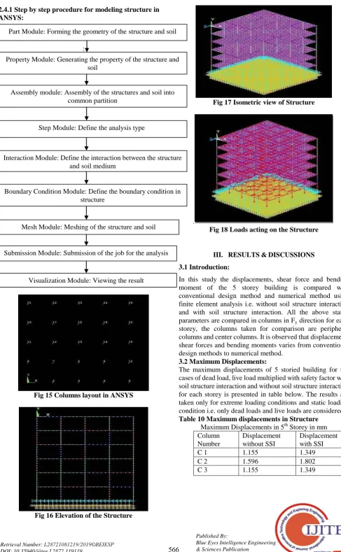
2.4.1 Step by step procedure for modeling structure in ANSYS:
:
[image:10.595.49.537.43.833.2]Fig 15 Columns layout in ANSYS
[image:10.595.329.525.52.182.2]Fig 16 Elevation of the Structure
Fig 17 Isometric view of Structure
.
Fig 18 Loads acting on the Structure
III. RESULTS & DISCUSSIONS 3.1 Introduction:
In this study the displacements, shear force and bending moment of the 5 storey building is compared with conventional design method and numerical method using finite element analysis i.e. without soil structure interaction and with soil structure interaction. All the above stated parameters are compared in columns in Fy direction for each storey, the columns taken for comparison are peripheral columns and center columns. It is observed that displacement, shear forces and bending moments varies from conventional design methods to numerical method.
3.2 Maximum Displacements:
The maximum displacements of 5 storied building for the cases of dead load, live load multiplied with safety factor with soil structure interaction and without soil structure interaction for each storey is presented in table below. The results are taken only for extreme loading conditions and static loading condition i.e. only dead loads and live loads are considered. Table 10 Maximum displacements in Structure
Maximum Displacements in 5th Storey in mm Column
Number
Displacement without SSI
Displacement with SSI
C 1 1.155 1.349
C 2 1.596 1.802
C 3 1.155 1.349
Part Module: Forming the geometry of the structure and soil
Property Module: Generating the property of the structure and soil
Assembly module: Assembly of the structures and soil into common partition
Step Module: Define the analysis type
Interaction Module: Define the interaction between the structure and soil medium
Boundary Condition Module: Define the boundary condition in structure
Mesh Module: Meshing of the structure and soil
Submission Module: Submission of the job for the analysis
Maximum Displacements in 4th Storey in mm
Column Number
Displacement without SSI
Displacement with SSI
C 1 1.119 1.33
C 2 1.555 1.79
C 3 1.119 1.33
Maximum Displacements in 3rd Storey in mm
Column Number
Displacement without SSI
Displacement with SSI
C 1 1.020 1.331
C 2 1.41 1.798
C 3 1.020 1.331
Maximum Displacements in 2nd Storey in mm
Column Number
Displacement without SSI
Displacement with SSI
C 1 0.857 1.331
C 2 1.173 1.791
C 3 0.857 1.331
Maximum Displacements in 1st Storey in mm
Column Number
Displacement without SSI
Displacement with SSI
C 1 0.659 1.31
C 2 0.860 1.7
C 3 0.659 1.31
Maximum Displacements in G.L in mm
Column Number
Displacement without SSI
Displacement with SSI
C 1 0.340 1.31
C 2 0.460 1.71
C 3 0.34 1.301
Graph 1 Maximum displacement in 5th storey with and without soil structure interaction
Graph 2 Maximum displacements in 4th storey with and without soil structure interaction
Graph 3 Maximum displacements in 3rd storey with and without soil structure interaction
Graph 4 Maximum displacements in 2nd storey with and without soil structure interaction
Graph 5 Maximum displacements in 1st storey with and without soil structure interaction
Graph 6 Maximum displacements in G.L with and without soil structure interaction
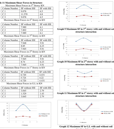
3.3 Maximum Shear Forces:
Effect of Soil Structure Interaction on Multi-Storeyed Building with Raft Foundation
Table 11 Maximum Shear Forces in Structure Maximum Shear Forces in 5th Storey KN
Column Number SF without SSI SF with SSI
C 1 9.078 6.5
C 2 11.570 6.8
C 3 9.078 6.5
Maximum Shear Forces in 4th Storey in KN
Column Number SF without SSI SF with SSI
C 1 7.989 6.1
C 2 7.892 5.9
C 3 7.989 6.1
Maximum Shear Forces in 3rd Storey in KN
Column Number SF without SSI SF with SSI
C 1 7.948 5.91
C 2 8.85 6.23
C 3 7.945 5.91
Maximum Shear Forces in 2th Storey in KN
Column Number SF without SSI SF with SSI
C 1 7.945 5.91
C 2 8.74 6.23
C 3 7.945 5.91
Maximum Shear Forces in 1st Storey in KN
Column Number SF without SSI SF with SSI
C 1 6.720 4.431
C 2 5.724 4.22
C 3 6.720 4.431
Maximum Shear Forces in G.L in KN
Column Number SF without SSI SF with SSI
C 1 3.045 2.79
C 2 1.529 1.43
C 3 3.045 2.79
Graph 7 Maximum SF in 5th storey with and without soil structure interaction
Graph 8 Maximum SF in 4th storey with and without soil structure interaction
Graph 9 Maximum SF in 3rd storey with and without soil structure interaction
Graph 10 Maximum SF in 2nd storey with and without soil structure interaction
Graph 11 Maximum SF in 1st storey with and without soil structure interaction
Graph 12 Maximum SF in G.L with and without soil structure interaction
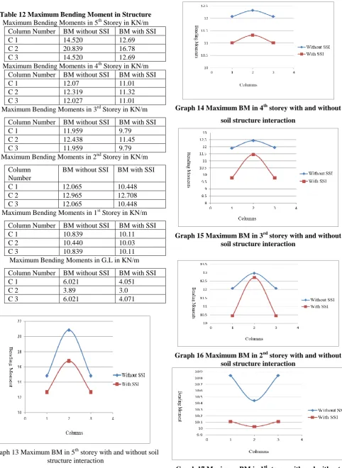
3.4 Maximum Bending Moments:
Table 12 Maximum Bending Moment in Structure Maximum Bending Moments in 5th Storey in KN/m
Column Number BM without SSI BM with SSI
C 1 14.520 12.69
C 2 20.839 16.78
C 3 14.520 12.69
Maximum Bending Moments in 4th Storey in KN/m
Column Number BM without SSI BM with SSI
C 1 12.07 11.01
C 2 12.319 11.32
C 3 12.027 11.01
Maximum Bending Moments in 3rd Storey in KN/m
Column Number BM without SSI BM with SSI
C 1 11.959 9.79
C 2 12.438 11.45
C 3 11.959 9.79
Maximum Bending Moments in 2nd Storey in KN/m
Column Number
BM without SSI BM with SSI
C 1 12.065 10.448
C 2 12.965 12.708
C 3 12.065 10.448
Maximum Bending Moments in 1st Storey in KN/m
Column Number BM without SSI BM with SSI
C 1 10.839 10.11
C 2 10.440 10.03
C 3 10.839 10.11
Maximum Bending Moments in G.L in KN/m
Column Number BM without SSI BM with SSI
C 1 6.021 4.051
C 2 3.89 3.0
C 3 6.021 4.071
Graph 13 Maximum BM in 5th storey with and without soil structure interaction
Graph 14 Maximum BM in 4th storey with and without soil structure interaction
Graph 15 Maximum BM in 3rd storey with and without soil structure interaction
Graph 16 Maximum BM in 2nd storey with and without soil structure interaction
Effect of Soil Structure Interaction on Multi-Storeyed Building with Raft Foundation
or-1 Photo
or-1 Photo Graph 18 Maximum BM in G.L with and without soil
structure interaction
IV. CONCLUSION
The displacements, shear forces and bending moments are estimated from conventional design method and numerical analysis method using finite element method in columns i.e. without soil structure collaboration and with soil structure association. The relocations, Shear powers and twisting minutes are contrasted and soil structure connection and without soil structure cooperation. The estimation of sub grade modulus response ( Ks) have been expected 12000 KN/m3.
The accompanying ends have been drawn from above outcomes:
Analysis of structure with soil structure collaboration indicates more removal than the investigation of structure without soil structure association.
Analysis of structure with soil structure
communication indicates less shear powers as contrasted and examination of structure without soil structure connection.
Analysis of structure with soil structure interaction shows more or less Bending moments as compared with analysis of structure without soil structure interaction.
Analysis of structure with soil structure interaction shows avg of 38% increase in displacements compared with analysis of structure without soil structure interaction.
Analysis of structure with soil structure interaction shows avg of 29.6% decrease in shear forces compared with analysis of structure without soil structure interaction.
Design performed by conventional method is high safe as we are designing the structure for higher shear forces and higher bending moments.
Conventional method of design is somewhat
uneconomical as the structure is design for higher shear forces and higher bending moments, so we can go for a structure designed by considering soil structure interaction.
REFERENCES
1. K. Natarajan and B. Vidivelli 2009 : Effect of column spacing on the behaviour of frame raft and soil systems.
2. Haytham Adnan Sadeq, Mohammed saleem Taha 2009: Structural design of raft foundation with soil structure interaction.
3. H.S Chore , V.A Sawant and R.K Ingle 2012: Non-linear analysis of pile groups subjected to lateral loads.
4. Sushma Pulikanti and Pradeep kumar Ramancharla 2013: SSI Analysis of framed structures supported on pile foundations
5. Vivek Garg and M.S Hora 2012: A review on interaction behavior of structure foundation soil system.
6. R. R. Chaudhari, Dr K. N. Kadam 2013: Effect Of Piled Raft Design On High-Rise Building Considering Soil Structure Interaction.
7. Gaikwad M.V, Ghogare R.B, Vagessha S. Mathada 2015: Finite element analysis of frame with soil structure interaction.
8. Lou Menglin, Wang Huaifeng, Chen Xi Zhai Yongmei 2011: Structure soil Structure interaction: literature review.
9. Dr. M. Reza Emami Azadi, Ali Akbar Soltani 2010: Effect of soil structure interaction on dynamic response of Delijan cement storage silo under earthquake loading.
10. D. Daniel Thangaraj and L Ilampathi 2012: Numerical analysis of soil raft foundation and space frame system.
11. Eduardo Kausel 2010: Early history of soil structure interaction. 12. IS 875 (Part-3)-1987 Indian Standard Code of Practice for “Design of
Wind Loads for Buildings and Structures”.
13. IS 456:2000 Indian Standard Code of Practice for “Plain and Reinforced concrete design”.
14. IS 1893 (Part-4)-2002 Indian Standard “Criteria for Earthquake Resistant Design of Structures”.
AUTHORS PROFILE
Korrapati Pratyusha, M.TECH [SE], Assistant professor in Department of Civil Engineering, Narasaraopeta Engineering college (Autonomous), Narasaraopet. She had published several research papers in various Scopus Indexed Journals. she had good experience Teaching Pedagogy, had attended for several workshops and conferences in the field of civil engineering, having hands-on experience on several finite element software and continuously carrying out her research in the field of Structural Engineering.
Doredla Nagaraju, M.TECH [SE], M.B.A, working as Assistant professor in Department of Civil Engineering, Narasaraopeta Engineering College (Autonomous), Narasaraopet. APE member of Engineering council of India, Associate member of Institution of Engineers (India), Life Member of Indian Society for Technical Education, Jr.Associate Member of American Society of Civil Engineers, had published several research papers in various Scopus Indexed journals, had attended for several workshops and conferences in the field of civil engineering, having hands-on experience on several finite element software and continuously carrying out his research at diverse areas by extending the study in the field of Structural Engineering.