Performance of Boost Converter with Fuzzy Logic
Controller to Increase the DWIG Speed Range in
Wind Power System
C Surya Prakash
Abstract-In this paper the wind energy conversion with avariable speed of wind turbine connected to the grid which is based on dual stator induction generator (DWIG) which is excited by Static Excitation Controller (SEC) on the Control winding side which utilized by Control –Winding Voltage Oriented Control (CWVOC), and followed by Step up converter at the power winding side which utilized Fuzzy Logic Controller in its control strategy to increase the speed range of DWIG. The performance of boost converter with FLC in increasing the wide range of speeds can be executed by using mat lab/Simulink.
Index terms: Control –Winding Voltage Oriented Control (CWVOC), Dual Stator Winding Induction Generator (DWIG), Fuzzy Logic Controller (FLC), Semiconductor Excitation Capacitor (SEC)
I. INTRODUCTION
Wind power generation has become an attractive consideration because of the rapid utilization of non- renewable energy sources and the expanding natural concerns. Normally 10%-12% of overall electrical energy is producing from wind power, due to drastically changing concerns in the world by 2030 there would be an inclination in the production of wind energy since it is a renewable source of energy [1].
Earlier wind turbines were utilizing squirrel cage induction generators for grid connection, but due to its constant rotor speed which will not match the incoming variable wind speed and gear box problems and even it is not used for obtaining maximum power. By considering all this constraints power electronic converters were introduced along with generators which is suitable for variable speed systems [2]-[3]. While most of the variable speed turbines are of costly, besides have higher efficiency. For economic considerations, Dual Stator Winding Induction Generators (DWIG) are introduced which are of low cost, but is of low efficiency. The wind condition is better at the offshore side to extract maximum wind power, so there is drastically appearing demand for offshore wind turbines. For economical transmission of power for longer distances High Voltage Direct Current (HVDC) transmission is utilized instead of AC transmission. Due to economic concerns and wide speed range operations DWIG systems are introduced in the offshore areas.
Revised Manuscript Received on November 2, 2019.
* Correspondence Author
*C Surya Prakash, M.Tech Scholar from Electrical & Electronics Engineering, JNTUA College of Engineering, Ananthapuramu, Andhra Pradesh, INDIA. Email: [email protected]
In this paper, the main aim is to increase the speed range of DWIG especially to obtain voltage in the low speed region. As the speed is low the output power obtained is also low, to obtain this a step up converter is utilized along with DWIG which increase voltage at low speeds DWIG consists of two windings namely control winding and power winding which are wounded under same stator slots, In control winding part, Static Excitation Capacitor (SEC) is used to vary capacitor voltage (Vdc) which regulates control winding voltage (Vc). By considering v/f characteristics of DWIG in the control winding side SEC utilizes Control Winding Voltage Oriented Control (CWVO). Generally DWIG can run at between 0.66-1.6 p.u speed range. In order to obtain voltage at low rotor speed and to increase speed range at low values than usual i.e., 0.4-1.6 p.u at control winding side SEC is utilized. In power winding part there is a capacitor which is connected along with 3-phase diode rectifier, the output of this is connected to step up converter which is used to increase the output voltage using MPPT technique. From step up converter the output is connected to grid .Finally the ideal speed range is obtained and simulated.
II. DWIG BASED CONFIGURATION
Fig.1.Power vs Speed curve of Wind turbine at different speeds(vw).
Fig.2. DWIG based configuration
SEC is connected to control winding of generator by inductor (LSEC) which is used to vary DC link voltage to turn off the diode which is connected in series with a low level voltage source, by varying the link voltage more than battery voltage. The control winding voltage is mainly varied by using SEC. The frequency is dependent on speed, at low speeds due to reduction in frequency the saturation of generator occurs .In order to avoid this by considering v/f strategy to increase voltage step up converter is utilized at power winding side A 3-stage rectifier and an excitation capacitor are connected on the power winding side. The rectifier converts AC voltage to DC voltage, similarly the rectifier converted varying voltage to constant DC voltage (VB1).Thus obtained voltage is adjusted at maximum level by using MPP. By governing the input current (IB1) of the step up converter this can be obtained, which prompts the control of the generator control winding current, just as the generator control. The yield voltage of the step up converter is directed at a higher steady state and used for HVDC transmission.
III. MATHEMATICAL APPROACH OF DWIG
The DWIG active voltage equations at d-q outline, in view of the technique, can be communicated as (1):
𝑉𝑐𝑑 = 𝑅𝑐𝑖𝑐𝑑− 𝜔𝜆𝑐𝑞 + 𝑑 𝜆𝑐𝑑
𝑑𝑡
𝑉𝑐𝑞 = 𝑅𝑐𝑖𝑐𝑞 + 𝜔𝜆𝑐𝑑+ 𝑑 𝜆𝑐𝑞
𝑑𝑡
𝑉𝑝𝑑 = 𝑅𝑝𝑖𝑝𝑞 − 𝜔𝜆𝑝𝑞 + 𝑑 𝜆𝑝𝑑
𝑑𝑡
𝑉𝑝𝑞 = 𝑅𝑝𝑖𝑝𝑞 + 𝜔𝜆𝑝𝑑 + 𝑑 𝜆𝑝𝑞
𝑑𝑡
𝑉𝑟𝑑 = 𝑅𝑟𝑖𝑟𝑑− 𝜔 − 𝜔𝑟 𝜆𝑟𝑞+ 𝑑 𝜆𝑟𝑑
𝑑𝑡 = 0
𝑉𝑟𝑞 = 𝑅𝑟𝑖𝑟𝑞− 𝜔 − 𝜔𝑟 𝜆𝑟𝑑+ 𝑑 𝜆𝑟𝑞
𝑑𝑡 = 0
− − − − − (1)
Where the rotor speed is ωr, angular synchronous frequency is ω and flux linkage, current, voltage are λ,i and v individually. The records r,p and c are identified with the rotor parameters, power- winding and control- winding. In power winding side both rotor and control parameters of winding are referred. Because of the squirrel confine sort of the rotor both q and d hub rotor winding voltages are zero. The linkage transitions conditions are depicted in (2):
𝜆𝑐𝑑 = 𝐿𝑐𝑖𝑐𝑑 + 𝐿𝑐𝑝𝑖𝑝𝑑 + 𝐿𝑐𝑟𝑖𝑟𝑑 𝜆𝑐𝑞 = 𝐿𝑐𝑖𝑐𝑞 + 𝐿𝑐𝑝𝑖𝑝𝑞 + 𝐿𝑐𝑟𝑖𝑟𝑞 𝜆𝑝𝑑 = 𝐿𝑝𝑐𝑖𝑐𝑑 + 𝐿𝑝𝑖𝑝𝑑 + 𝐿𝑝𝑟𝑖𝑟𝑑 𝜆𝑝𝑞 = 𝐿𝑟𝑐𝑖𝑐𝑞 + 𝐿𝑝𝑖𝑝𝑞 + 𝐿𝑝𝑟𝑖𝑟𝑞 𝜆𝑟𝑑 = 𝐿𝑟𝑐𝑖𝑐𝑑+ 𝐿𝑟𝑝𝑖𝑝𝑑 + 𝐿𝑟𝑖𝑟𝑑 𝜆𝑟𝑞 = 𝐿𝑟𝑐𝑖𝑐𝑞 + 𝐿𝑟𝑝𝑖𝑝𝑞 + 𝐿𝑟𝑖𝑟𝑞
− − − − − (2)
Where inductances are:
𝐿𝑐 = 𝐿𝑙𝑐 + 𝐿𝑙𝑐𝑝 + 𝐿𝑚 𝐿𝑝 = 𝐿𝑙𝑝 + 𝐿𝑙𝑐𝑝+ 𝐿𝑚 𝐿𝑟 = 𝐿𝑙𝑟 + 𝐿𝑙𝑐𝑝+ 𝐿𝑚 𝐿𝑐𝑝 = 𝐿𝑝𝑐 = 𝐿𝑙𝑐𝑝 + 𝐿𝑚
𝐿𝑐𝑟 = 𝐿𝑟𝑐 = 𝐿𝑚 𝐿𝑝𝑟 = 𝐿𝑟𝑝 = 𝐿𝑚
− − − − − (3)
in which Llr is the rotor-winding spillage , Llc is control-winding, Llp is power-winding inductances respectively and the magnetizing inductance is Lm. Where Llcp coupling leakage inductance can be disregarded in light of its irrelevant worth. Fig. 3 demonstrates the proportionate d-pivot and q-hub circuit models of the DWIG.
(b)
Fig.3 a) Equivalent circuit of DWIG in d-axis b) Equivalent circuit of DWIG in q-axis
IV. CONTROL APPROACH A) Excitation approach of DWIG:
To energize DWIG, the voltage of control-winding (Vc) modification is the primary job of SEC. To expand the yield voltage level, the step up converter is utilized in the proposed topology, for low-speed output V/f system can be used for
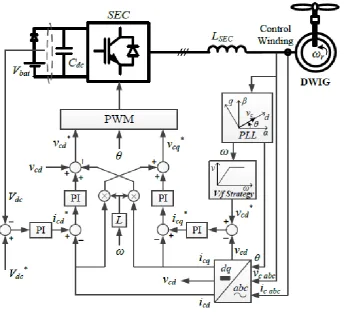
[image:3.595.91.516.49.163.2]DWIG excitation. The SEC DC-interface voltage (Vdc) must be managed at reference esteem for this reason. CWVO technique is utilized by SEC in order to alter the Vc and Vdc. Fig. 4 demonstrates the square chart of CWVO control methodology for DWIG.
Fig.4. CWVO excitation control approach. Adjusting the voltage in the winding side of control with the
d-pivot, the q-hub voltage (𝑣𝑐𝑞) ends up zero and the d-hub voltage (Vcd) approaches the plentifulness of the control-twisting voltage as in (4):
𝑉𝑐𝑑 = 𝑉𝑐
𝑉𝑐𝑞 = 0 − − − (4)
In this manner, as indicated by the prompt power hypothesis, the dynamic power winding side of control (pc) and static power (qc) are:
𝑃𝑐= 3 2 𝑉𝑐𝑑𝑖𝑐𝑑
𝑞𝑐 = 3 2 𝑉𝑐𝑑𝑖𝑐𝑞
− − − (5)
For vcd in equ (1), winding obstruction voltage loss (Rcicd) is disregarded and the control-winding d-pivot motion is thought to be consistent(𝑑𝜆𝑐𝑑/𝑑𝑡 = 0), at that point:
[image:3.595.130.475.312.629.2]𝑃𝑐 ≅ − 3
2𝜔 𝜆𝑐𝑞𝑖𝑐𝑑
𝑞𝑐≅ + 3
2𝜔 𝜆𝑐𝑞𝑖𝑐𝑞
− − − (7)
By constraining icd and icq individually, the demonstration of control-winding dynamic and receptive power can be done. The power balance connection between the control-winding and SEC DC-connection can be communicated as in Equ (8):
𝜕(12𝐶𝑑𝑐𝑉𝑑𝑐2)
𝜕𝑡 + 𝑃𝑆𝐸𝐶 _𝑙𝑜𝑠𝑠 = −𝑃𝑐− −(8)
Where PSEC_loss is the loss in power and Cdc is the Direct Current-interface capacitor of SEC . Like a Synchronous Static Compensator (STATCOM), for its internal loss of power SEC utilizes small amount of active power, when trading receptive influence; generally, the DC-interface voltage would not be steady. Accordingly, Vdc can be constrained by dynamic power of control winding. The flux linkage on the winding of control side (λcq) can be controlled by static power on the winding of control side (qc) at similar speeds. Equ (9) can be shown by utilizing the flux linkage on winding side of control λcq and static power qc, surrendered Equ (2) and Equ (7) separately.
𝜆
𝑐𝑞𝜆
𝑐𝑐𝑞= 𝑞
𝑐.
𝐿𝑠
𝜔
− − − (9)
where λccq is a subset of the flux linkage on the side of control part λcq, prompted by isq in the winding side of control part. Then again, Equ (4) and Equ (6) demonstrate that by controlling the winding side of control part q-pivot transition (λcq), the abundancy of winding voltage at control side can be balanced. In this way considering Equations (7), (8), and (9), it very well may be communicated that:
𝑖𝑐𝑑 ⟹ 𝑝𝑐⟹ 𝑉𝑑𝑐
𝑖𝑐𝑞 ⟹ 𝑞𝑐 ⟹ 𝜆𝑐𝑞 ⟹ 𝑉𝑐− − − −(10)
Condition (10) shows that by the control of icd and icq separately, the voltage at winding side of control Vc, DC couple voltage Vdc can be precised.
In the CWVO excitation of DWIG as appeared in Fig. 4, To control icd and Icq independently and the DWIG free parameters the controller utilizes a methodology of decoupling with PI controllers in the loop of current. To decide the winding side of control part d-hub current of reference (icd*), Vdc is contrasted and its reference esteem and the yield blunder is gone through a controller of PI. So also, the q-pivot reference current (icq*) is gotten by contrasting Vcd and its reference worth and utilizing another controller of PI. At the minimum-recurrence activity, relating to minimum speed of generator, methodology of V/f is applied, therefore Vsd* is resolved by the working recurrence.
B) MPPT strategy of Boost converter
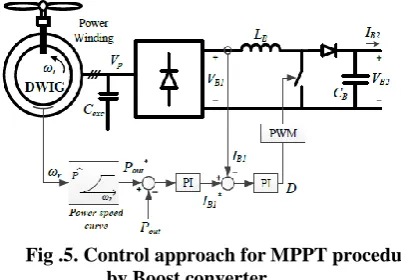
The voltages of DWIG are varied by applying energy at control side, the step up converter controls the dynamic power of generator dependent on MPPT. By V/f methodology, the step up converter gives a wide speed scope of activity, including minimum condition of speed, where the voltage of DWIG is decreased. Step converter suits the expansion in the yield voltage and associates the higher level voltage generator. For MPPT, the methodology of control introduced is utilized. The step up converter control plot has appeared in Fig. 5.
Fig .5. Control approach for MPPT procedure by Boost converter
To accomplish MPPT, converter utilizes a table, which is obtained from the curves of speed vs power exhibited in Fig.1. The ideal power (Pout*) is put away in table, for all speed of DWIG (ωr) . By the consideration of the ideal power is as a reference control in the step up controller to change the yield control at MPP. In the event that the step up converter control misfortune is disregarded, the yield influence (Pout)
𝑃𝑜𝑢𝑡 = 𝑉𝐵2𝐼𝐵2 ≅ 𝑉𝐵1𝐼𝐵1− − − (11)
VB1 shall be composed as a steady proportion of the voltage of winding of power side if the voltage drop of rectifier is disregarded. Meanwhile the same air gap flux has been experienced by both the windings, controlling the control-twisting voltage prompts guideline of winding voltage intensity. In this way by replacing both the winding voltages by bearing in mind loss of impedance of generator. The voltage drop relies upon both currents of winding which are controlled by voltage on control winding side and current of rectifier/step up converter. Along these lines, VB1 and Pout can be communicated by (12) and (13), individually:
𝑉𝐵1= 3 2
𝜋 . 𝑈𝑝 = 3 2
𝜋 . 𝑛𝑝 𝑛𝑐
. 𝑈𝑐− ∆𝑈 𝐼𝐵1𝑈𝑐 − − − (12)
𝑃𝑜𝑢𝑡 = 3 2
𝜋 . 𝑛𝑝 𝑛𝑐
𝑈𝑐− ∆𝑈 𝐼𝐵1𝑈𝑐 . 𝐼𝐵1− − − (13)
Where Up and Uc indicate the intensity winding line voltage and control-twisting individually; ΔU is the change in voltage crosswise over control-winding and power-winding;
n
p/n
c is the windings turns ratio. Since Ucis managed by thecontrol excitation to its esteem reference, Pout - yielded in Equ (13) - can be constrained by IB1. So in the power guideline circle, Pout is contrasted and its reference worth and
[image:4.595.333.534.55.195.2]V. FUZZY LOGIC CONTROLLER
Fuzzy logic controller (FLC) mainly depends on the rules based. It is the form of input and output. The FLC input has two values like error value and change in error value. The output value depends upon the input values and rules configuration. The limits of variable between -1 to 1. The truth value of Boolean logic the variables may be 0 or 1. The fuzzy logic controller has classified into following types as Fuzzification, rule matrix, Defuzzification. The below circuit diagram explains the relations between three controllers.
Fig.6. Fuzzy logic analysis and control Fuzzy rules are classified depends upon input and output membership functions. The schematic circuit diagram of
membership functions shown below
Input 1 Membership Function
Input 2 Membership Function
Output Membership Function
In FLC input values of error and change in error and the output. The rules are combination of 5 triangle functions for each. These fluffy sets are interfaced by 'negative huge (NB)', 'negative little (NS)', 'positive little (PS)', 'Zero (Z)', and 'Positive Big (PB)' for each fluffy participation capacities. The fluffy principles are directional by 25 for the five elements of blunder and change in mistake (Contribution of the FLC)
Table: 1 Rule based fuzzy table
Δe
e
NB
NS
ZO
PS
PB
NB
NB
NB
NB
NS
ZO
NS
NB
NB
NS
ZO
PS
ZO
NB
NS
ZO
PS
PB
PS
NS
ZO
PS
PB
PB
PB
ZO
PS
PB
PB
PB
Fig.7. Boost control strategy with fuzzy logic controller configuration
VI. SIMULATION RESULTS A) Simulation results by using PI controller:
Fig.8. Simulation results of 2.3Micro grid by using Pi controller
B) Simulation results by using fuzzy logic controller: By using the boost converter with FLC increase the speed and improve the power. In this project by considering the boost converter by using Simulink shown below.
Fig.9. Simulation results of 2.3Micro grid by using Fuzzy logic controller
VII.CONCLUSION
In this paper discussing about increasing the speed range of doubly winding induction generator by using boost converter along with fuzzy logic controller. For broad speed range and MPPT a step up converter is employed, particularly at minimum-speed showed up. At minimum speed, DWIG voltage is discarded because of v/f control system and a step up converter is utilized to expand the voltage level to meet the sophisticated and consistent voltage prerequisite, In this paper by replacing fuzzy logic controller in the place of PI controller we can obtain bulk values at low speed region and at nominal speed region so that speed range is increased in the results of DWIG and boost converter. The performance of DWIG and boost converter can be evaluated by using mat lab/Simulink
REFERENCES
1. REN21, “Renewables 2016: Global status report,” 2016. [Online]. Available: http://www.ren21.net.
2. F. Blaabjerg and K. Ma, "Future on Power Electronics for Wind Turbine Systems," IEEE Journal of Emerging and Selected Topics in Power Electronics, vol. 1, no. 3, pp. 139-152, Sept. 2013.
3. Z. Chen, J. M. Guerrero, and F. Blaabjerg, "A Review of the State of the Art of Power Electronics for Wind Turbines," IEEE Transactions on Power Electronics, vol. 24, no. 8, pp. 1859-1875, Aug. 2009. 4. V. Yaramasu, B. Wu, P. C. Sen, S. Kouro and M. Narimani,
"High-power wind energy conversion systems: State-of-the-art and emerging technologies," Proceedings of the IEEE, vol. 103, no. 5, pp. 740-788, May 2015.
5. H. Nian and Y. Song, "Direct Power Control of Doubly Fed Induction Generator Under Distorted Grid Voltage," IEEE Transactions on Power Electronics, vol. 29, no. 2, pp. 894-905, Feb. 2014.
6. H. Li, and Z. Chen, “Overview of different wind generator systems and their comparisons,” IET Renew. Power Gener., vol. 2, no. 2, pp. 123-138, Jun. 2008.
7. S. M. Muyeen, R. Takahashi, and J. Tamura, "Operation and Control of HVDC-Connected Offshore Wind Fa
AUTHORSPROFILE