The Personal Distributed Environment
Robert C Atkinson
∗, James Irvine
∗, John Dunlop
∗and Sunil Vadgama
†∗
Mobile Communications Group,
Institute for Communications and Signal Processing,
Dept. Electronic & Electrical Eng.,
University of Strathclyde,
Glasgow, G1 1XW, UK,
Email:
{
r.atkinson, j.irvine, j.dunlop
}
@eee.strath.ac.uk
†
Fujitsu Laboratories of Europe Ltd
Hayes Park, Hayes End Road,
Hayes, Middlesex, UB4 8BE, UK
Email: s.vadgama@
fl
e.fujitsu.com
Abstract— Network evolution Beyond 3G continues to domi-nate discussion within the cellular community. A variety of issues are being actively debated: requirement for a new air-interface, greater interworking with WLAN and other networks, service-driven approach, and potential for increasing market penetration of network-enabled devices. The Mobile VCE vision for Beyond 3G encompasses a world that has embraced a disparate range of networked processing and communications devices. This paper presents an architecture for user-centric communication across heterogeneous access networks.
I. INTRODUCTION
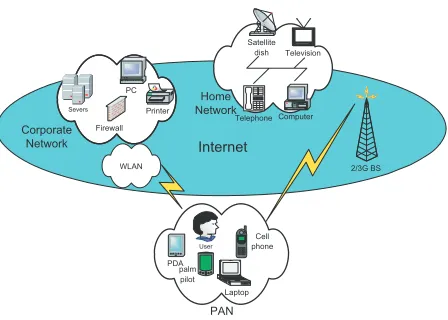
It is anticipated that in the future there will be a greater proliferation of wireless processing devices. These devices will include wireless enabled-laptops, PDAs and smartphones, to-gether with new and innovative devices such as environmental and biomedical sensors. Each will have its own distinct ca-pabilities and characteristics such as screen size & resolution, and the ability to support audio/video/other sessions. Thus, users will own and control a plethora of diverse devices, giving rise to the Personal Distributed Environment (PDE) concept [1]. The PDE is a personal networking solution aimed at providing access to a diverse range of services over these multifaceted terminals. User devices are organized into location-dependant (i.e. both local and remote) subnetworks; PDE is the means by which services can be delivered to the user over heterogeneous networks to these terminals. Unlike many initiatives, the PDE takes a user-centric approach; it is the user who manages the various subnetworks and controls session delivery.
The vision of mass distribution of wireless devices is not unique to PDE. Much research is being conducted on Ambient Networking [2]; a concept that has many interpretations, though context aware wireless connectivity is central to many of them. A closely related concept is that of Sensor Networks [3]: clusters of wireless interconnected sensors capable of measuring a range of qualities such as temperature and air pressure. Other research is focussing on the Mobile Grid: a collection of wireless processing devices that cooperate to share resources such as processor time and memory. More recently, an IST 6thframework project, My personal Adaptive
NETwork (MAGNET), has also examined the concept of personal networking. The central theme that underpins these initiatives is that of ad hoc networking.
In tandem with the research into increased wireless con-nectivity, interworking of access networks has received much attention recently. Current advances in 802.11 Wireless LAN (WLAN) technologies have motivated the standardization of WLAN-UMTS interworking through 3GPP Release 6. In-creased deployment of digital broadcast systems such as Digi-tal Video Broadcasting (DVB) and DigiDigi-tal Audio Broadcasting (DAB) has led industrial players to examine the possibility of DxB-cellular interworking through initiatives such as the DVB group: Convergence of Broadcast and Mobile Services (CBMS).
It is the unification of these trends that gives rise to the PDE concept pioneered by the Mobile Virtual Centre of Excellence (MVCE) [4].
The remainder of this paper is arranged as follows: Section II provides an outline of the PDE Architecture, describing the main entities and their roles. Section III presents discussion on the physical location of the functional entity that manages a subnetwork. Section IV examines the need for location privacy within the PDE. Finally, Section V provides a summary and outlines areas of future research.
II. PDE ARCHITECTURE
A key objective of the PDE is to provide virtual personal network connectivity in a dynamic and heterogeneous envi-ronment, irrespective of device location. Therefore, enabling not only ubiquitous access to a user’s own personal devices and network space, but also access to global communication and information services.
The design of the architecture is constrained by the need to ensure ubiquitous connectivity; this translates into a re-quirement for a nominated contact point for each user with a unique address, permitting a DNS-like lookup procedure to readily return that address. Within the context of the PDE, this entity is known as the Device Management Entity (DME). A person-based URI is mapped to the IP address of the DME. All session set-up requests irrespective of the their type (voice call, email, etc.) are sent to this URI. Intelligent management functionality resident within the DME preforms intelligent end point determination for each service; this permits the most appropriate device to be chosen to suit the session. The user-centric nature of the PDE gives rise to the notion of a DME containing much of the functionality of a user-based proxy. The proxy operates on behalf of a single individual and is based on the IETF Session Initiation Protocol (SIP) [5]. The idea is that the DME contains the functionality of a SIP proxy and other additional functionality required to manage the PDE. Given the assumption that the user will exercise control over a variety of communication devices, SIP is an ideal technology for a rendez-vous protocol that facilitates location tracking, permitting the user to be contacted irrespective of location. One of the unique aspects of the PDE is that it encompasses both local (e.g. within the user’s PAN) and remote (e.g. within the user’s household) devices. Thus, SIP can be used to direct session set-up requests to the appropriate device, based on user location and also device capabilities. The session set-up requests from other parties can describe the required characteristics of end terminals using the Session Description Protocol (SDP) [6]. Within the architecture, a Call Processing Language [7] acts as an interface between session requests received via SIP and the information stored in internal DME registers, as will now be explained.
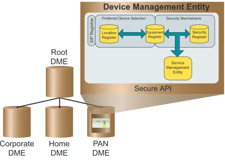
Central to PDE provision is a controlling logical functional entity known as the Device Management Entity, as shown in Figure 2. This entity contains a number of functional subcom-ponents, called registers, that assist in managing coordinated device operation and service delivery within the PDE [8].
The equipment register is used to store device capabilities and characteristics. A number of security issues are prevalent in distributed networks such as the PDE; the security register stores encryption keys for devices and security policies for the PDE as a whole.
The PDE may be viewed as a composite of several phys-ically separate subnetworks; in particular some of those net-works may exhibit high mobility profiles: e.g. the automobile network and the PAN. Thus, mobility management within the PDE requires a tracking entity. This task is performed by a DME subcomponent known as the location register: a com-ponent that provides a service analogous to the SIP location service. Implementation of the location service is not specified by the SIP specification and can therefore be implemented
using other appropriate technologies. The Berkeley database has been used to implement the location register; it is also being used to implement the other registers. Interaction with the database is conducted through the Lightweight Directory Access Protocol (LDAP) [9]. Conveniently, both database and access protocol are included in the open source software component, openLDAP. The DMEs and their registers were therefore implemented using openLDAP on a Mandrake 9.0 Linux platform.
In order to minimize the amount of signalling across the var-ious networks that the PDE transcends, a portion of the DME is devolved to each subnetwork to permit local management, as shown in Figure 2. Thus, each subnetwork is permitted to operate in a semi-autonomous fashion. However, data stored in each of the local DMEs is cached within the root DME. This two-level approach is beneficial since:
1) When a device wishes to determine the capabilities of a device in its own subnetwork, it contacts its local DME, reducing the need to communicate with the root DME directly. This is advantageous because the root DME will generally be further away; the increased hop count will result in increased latency. Moreover, communication with a local device may allow utilization of non-tariff based links.
2) When a device wishes to determine the capabilities of a device in another subnetwork, it is redirected by its local DME to the root DME, which has visibility of the characteristics of all devices. Thus, signalling is constrained to be local, where possible. This redirection, also known as referral, is preferred over a chaining approach in implementation. Chaining, where, the local DME would pass on the request on behalf of the device is beset by security problems.
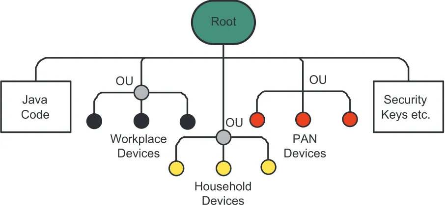
The PAN section of the PDE will encounter a range of foreign devices by virtue of its mobility. These could be either other users’ wireless-enabled devices or public wireless devices with integrated services that users may wish to utilize opportunistically. When the PAN encounters a foreign device, it may be added to its local DME’s internal registers such that devices within the PAN may access that foreign device/service. Many of these public devices will be designed to provide local services, e.g. a wireless-enabled machine at a railway station may provide travel tickets. The salient point is that local services will only be of value to the user when in the vicinity of those device/service. Based on the assumption that local user devices are more likely to interact with local services, foreign devices and services need only be mapped locally, i.e. in the local DME. This approach has the potential to minimize signalling of topological changes to other sections of the PDE, hence reducing the requirement for signalling over the wireless links that may incur a high tariff. The tree-like nature of LDAP permits the characteristics of devices located in different subnetworks to be stored in different branches under an organizational unit (ou), as shown in Figure 3. This technology facilitates delegation of authority to manage this information to the respective subnetworks.
two levels of management. The top-level management entity, therootDME, andlocalDMEs that are resident in each of the PDE subnetworks. Section III examines the physical location of the local DME.
III. PHYSICALLOCATION OFLOCALDME
Within each PDE subnetwork, local DME functionality will reside on one of the devices. In wireless subnetworks (with dynamic topology) it would be advantageous if the host could change to reflect variations in residual battery power or topology. Topological changes that may require a change of host include addition of a new node or subnetworks becoming co-located, i.e. resident at the same location. The former implies that a new node may be better able to support the DME management functionality. The latter implies that two or more wireless subnetworks belonging to the same user occupy the same radio environment; in this circumstance one copy of the management functionality may become redundant. An automated algorithm is used to identify the most appropriate device to host the local DME functionality; note the DME is not a form of piconet controller that controls access to the radio medium, rather it is a higher layer functional management entity. Nonetheless, the algorithmic approach to determining a suitable host for the DME has similarities to piconet controller selection mechanisms. The algorithm could consider such factors as availability of power1, processing power, memory
constraints, and optionally connectivity2. However, the
abun-dance of powerful personal computing devices, both within the household and workplace, is such that processing, memory and energy constraints are unlikely to be an issue for these devices. Therefore, the selection of a device to host the local DME in the fixed subnetworks is unlikely to be problematic. The same cannot be said, however, for the mobile subnetworks: energy capacity is a significant limiting factor due to the limited battery life of mobile devices. Successive generations of mobile handsets and PDAs have been accompanied by increased processing ability and storage capability. Based on this trend, it is unlikely that these constraints will be the limiting factor.
Although available processing power and storage capacity in a mobile device may be subject to temporal variation, it is residual battery power that will be the most dynamic. Based on this premise, the choice of the most suitable device to host the DME in a wireless network may vary with time; this poses the significant problem of how to determine the most suitable host. For implementation purposes it was decided to focus on selection algorithm based on residual energy.
Within the algorithm, the best candidate is defined as the node which has the highest level of residual energy. Each node that has sufficient processing power and storage capa-bilities (based on predetermined threshold values) broadcasts its estimated battery life on all local interfaces. The broadcast will take the form of a packet that contains the candidate’s
1Clearly devices that have access to afixed supply are preferable to devices
relying on battery power. Similarly, devices with large residual battery power are preferable to those with little remaining power.
2Ability to communicate directly with other devices within the subnetwork,
particularly over heterogeneous links.
address (or range of addresses for a multimode device), a global PDE identifier, a handoverflag, the estimated battery life, a magic number3, and a time-to-live count. The packet
may be encrypted so as to prevent other wireless devices from intercepting transmissions. On reception of the broadcast packet, the other devices in the subnetwork decrement the time-to-live counter. If the counter value is non-zero then the packet is re-broadcast on all available local interfaces. Where a device has multiple interfaces it may receive multiple copies of the packet. In this case the device can use the magic number to determine whether it is the same packet or another packet: loop detection; clearly, a node will not broadcast a packet that it has broadcast previously. In this way each device in the subnetwork is made aware of the DME’s location, i.e. the MAC address of the DME’s host device within the subnetwork. The maximum number of times that the broadcast packet need be transmitted can be determined. For a network con-taining N devices (D1−DN), where each device hasIn local
interfaces, then the number of broadcast packets is given by:
P kts=
N
n=1
In (1)
All nodes in the subnetwork are able to receive these broadcasts; when the handoverflag is set, the candidate with the longest battery life is regarded as the most suitable device. The successful candidate will assume the role of DME host and will commence periodic transmission of beacon packets. Beacon packets are defined as broadcast packets with the handoverflag reset. The purpose of the broadcast packets is two-fold. Other devices use these to determine the address of their local DME - when the handover flag is zero. Their secondary purpose is to allow other candidate hosts to continue monitoring their residual power and compare it with that broadcast - when the handoverflag is 1. If the incumbent host falls below an acceptability threshold (i.e. a residual energy threshold) and another candidate has a significantly better projected battery life then it replies by transmitting its estimate to the incumbent host. For another device to be considered as better, two conditions must exist: the incumbent breaches its minimum energy threshold, and the candidate has a battery life greater than that of the incumbent plus a hysteresis margin. This approach is adopted in order to avoid unnecessary handover of the DME hosting role, which is undesirable since handover involves transferring computer code and data to the successor, incurring a cost in terms of power & bandwidth consumption. Estimation of battery life may be subject to measurement error; therefore, the hysteresis margin is required to prevent ping-pong handovers. If the incumbent host is able to support the DME despite the presence of another more suitable candidate, a handover is not required. Opting not to handover in this circumstance avoids the cost associated with handover. It is for this reason that a minimum power threshold must be breached before handover is triggered.
In order to determine the performance of the algorithms and techniques 2 metrics will be used, For a simulation consisting
3A random number generated by nodes and inserted into a packet to enable
of a set, N, ofxnodes such that N ={n1...nx}, a setT of
their respective lifetimes is obtainedT ={t1...tx}. The setT
is used to calculate the metrics.
1) Mean Node Lifetime (m1): this is the mean value taken across all node that form the ad hoc network:
m1=
x
i=1Ti
x (2)
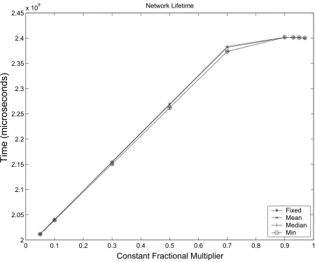
2) Network Lifetime (m2): this is the time that the entire ad hoc network is still operational without any node failures due to battery power. Since the network will no longer be regarded as fully operation on the failure of a single node, then this metric translates into the shortest lifetime of all nodes in the simulation.
m2=min(T) (3)
Since handover selection is triggered whenever the current DME falls below the energy threshold value, it follows that when all nodes are below that value the network will be in a condition of permanent DME selection. The signalling traffic this incurs leads to rapid energy consumption on all nodes. It is worth noting that energy consumption results not just from transmission of (signalling) packets but also from reception. A device will consume battery energy every time it transmits a packet. Additionally, every device within radio range of the transmitter will consume energy in order to decode it, and these devices will process the packet in one of two ways. If the device is the intended recipient it will decode the layer-2 frame and pass it up the IP stack for further processing; if it is not the intended recipient, it will decode the frame, examine the address, then discard it: a process known as overhearing. Studies of 802.11-based networks have shown that energy consumed during reception is almost equal to that consumed during overhearing [10] at low transmission power levels, e.g. 1mW.
It is therefore important to recognise the effect of threshold value on battery life:
• High threshold values lead to short node life. This is the
result of continual controller selection once all nodes are below the threshold. Before this occurrence, a handover is triggered relatively infrequently and therefore the asso-ciated energy overhead is small. The higher the threshold value, the sooner all nodes are below that value. Since handovers are triggered whenever the controller node is below the threshold value, continual controller selection (and hence signalling) results.
• Low threshold values lead to high variation in node
lifetime. This is because handover only occurs when the first node to become the local DME has almost exhausted its energy reserves.
In a network where all nodes are within radio range of each other (i.e. a fully interconnected mesh), it is clear that the state of continual leadership elections will lead to catastrophic effect in terms of battery life. To prevent this situation a dynamic threshold value is required. Consequently, another algorithm is required to determine the new value of this threshold.
Four approaches have been simulated and assessed:
• Fixed Percentage: The handover threshold is set to afixed
percentage (say 90%) of its previous value.
• Percentage Of Mean: The handover threshold is set to a
fixed percentage of the mean residual energy of all nodes.
• Percentage Of Median: The handover threshold is set to
a fixed percentage of the median residual energy of all nodes.
• Percentage Of Minimum: The handover threshold is set
to afixed percentage of the lowest residual energy of all nodes.
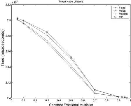
Each of the four cases have been evaluated and compared. Their performance is assessed with the metrics described in Equations 2 & 3 across a range of fixed percentages. In all four cases the first iteration is triggered to occur at 90% of the energy level of the nodes. Thereafter, the threshold is adjusted according to the appropriate algorithm. Common to all these approaches is that the new threshold value is set to a percentage or fraction of either the previous value or a measure of node energy. This is achieved by multiplying the measure by a constant factor between 0 and 1: this factor will be referred to as the Constant Fractional Multiplier (CFM).
Simulation revealed that each of the four approaches, for a range of CFM values, led to similar results in terms of node and network lifetime; the difference between the best and worst performing scheme was typically less than 1%, even when the nodes had nonuniform initial energy values as shown in Figures 4 & 5. The simulations did reveal, however, that the correct choice of CFM could extend mean node lifetime by 4% and network lifetime by 16%. If it is of critical importance to keep all devices in the network alive as long as possible then a high value of CFM should be chosen in the region of 0.85. If the objective is to keep only one device in the network alive as long as possible then a small value of CFM should be chosen, in the region of 0.1. High values of CFM lead to more frequent handover selections and this distributes the load of hosting the local DME more evenly across the devices in the subnetwork. Low values of CFM should be chosen since fewer handover selections lead to lower energy consumption as a result of the signalling entailed. In this case handover is only preformed when the current host is close to power failure. This results in significant variations in device lifetimes within the network, but has the advantage that one of the devices will have a long lifetime.
then the subnetworks are said to have merged. The benefit of a single DME is derived from battery power conservation, and increased knowledge base. The former implies that it is more power efficient for a single device to be assigned that task of managing a network than to have several devices performing this task in parallel. The latter implies that better decision making is possible by a single DME with access to full information with the subnetwork than by two or more DMEs with access to a subsection of information.
As mentioned DME hosts periodically broadcast packets detailing their appropriateness to host the DME. Therefore, when PDE subnetworks become co-located, both hosts will be able to receive each others packets. On mutual reception of packets, that with the longer battery life (plus hysteresis margin) is identified as the most appropriate host. However, it is not necessary to merge both DMEs immediately. It is pro-posed that merging of DMEs is postponed until a predefined time period has elapsed. The purpose of this time period is to avoid merging and disjoining of local DMEs when PDE subnetworks become co-located for short time periods such as a short car journey. During this period the subnetworks will continue to be managed independently. After this period, however, it is proposed that a single DME entity manages the conjoined subnetworks.
Merging of DME logical entities is achieved as follows. The DME host that does not have precedence, i.e. has the lower battery life, indicates that it is willing to handover copies of its registry information to the DME host with precedence. On receipt of an acknowledgement, copies of the records held in the registries are transmitted. It should be noted that the former DME host does not depopulate its database; rather it simply stores it but no longer operates as a DME. The rationale for retaining this information is that it may be needed in the near future if the PDE subnetworks become disjoined again.
Within PDE a range of security issues are being examined: Digital Rights Management (DRM), trust of foreign entities, Single Sign-On mechanisms (SSO), and location privacy. DRM mechanisms are required to permit the user to transfer content across their devices but not to others’ devices with-out payment. Trust management is required for opportunistic communication; should a PDE device trust another device or service provider if it has no previous experience of that device? SSO permits the PDE to authenticate to many access networks by authenticating with only one of them; this also facilitates aggregated billing mechanisms. The transfer of signalling traffic between local and root DME entities may reveal the user’s location to other parties. Indeed, monitoring a media session could also reveal a user’s end point. Thus, location privacy is an important consideration in Personal Networking. The issue of location privacy is discussed in Section IV.
IV. LOCATIONPRIVACY
Since each of the PDE subnetworks is physically separate, they will exchange signalling information over intermediate networks: UMTS networks, WLAN networks, and ISP/telcos. Clearly, within the intermediate networks there exists the possibility that a user’s location privacy requirements could
be violated using traffic analysis. In fact, it is not possible in any such system to completely obscure location information. However, within the PDE there exists an additional danger to the PDE’s location register [11]. Accurate knowledge of the PDE’s topology relies on the location register being supplied with true information. From a security perspective, this highlights the need to ensure that the database is not supplied with misinformation regarding topological changes.
The misinformation may arise from two sources: malicious devices/users, and malfunctioning devices/networks. With the former case, a malicious source may attempt to deliberately mislead the location register as to the true topology of the PDE. For example, it may attempt to inform the location register that the devices residing in a user-based PAN are erroneously contactable through a WLAN network (with sup-plied gateway address). Based on this information the root DME is misled with regards to the true contact information of the PAN. Of course, the malicious entity need not be a source, rather it could be an entity resident in an intermediate network that tampers with originally correct information. This is undesirable since it would result in a section of the PDE (in this case the PAN) becoming detached from the rest (out of contact with the PDE). With the latter case, a malfunctioning node may attempt to update its own topological database but unwittingly sends the information to the wrong destination (i.e. wrong DME address). Alternatively, a malfunctioning network may route accurately addressed information to the wrong destination: stray messages. In this case, it is possible that a section of a user’s PDE becomes conjoined with that of another user.
Both cases indicate that interception (substitution) of loca-tion informaloca-tion traversing the PDE can lead to secloca-tions of the PDE becoming detached from the rest (denial of service), or perhaps sections of another PDE becoming erroneously attached. Thus, interception of location information may have the effect of destabilizing the entire PDE. Clearly, there is a need for robust security mechanisms to operate between the root DME and its local components resident in each PDE subnetwork.
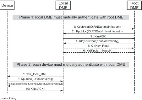
The root DME is able to decrypt this request using its private key and responds (message 2) with the same time info, random number, authentication request identifier, and session key (Klr). All of this is encrypted by the local DME’s
public key, Kpubloc. By including the random number in this
transaction, the root DME indicates that it has the private key and in doing so authenticates itself to the local DME. The local DME then authenticates to the root DME by transmitting an acknowledgement (message 3) encrypted using the session key contained in message 2. Finally, the root returns (message 4) an authentication token,Kprivroot{Klpuboc: validity}. The
authentication token is the local DME’s public key and validity information signed by the private key of the root DME. In this context validity information contains the ID of the local DME, and timing information to reveal the period for which the token can be used in order to prevent replay attacks. The local DME can use this token later to prove to other devices that it has previously been authenticated by the root DME. If the local DME has no prior knowledge of the otherN devices in its subnetwork, it can request (message 5) a copy of their public keys4 encrypted using the session key. The root DME
subsequently responds (message 6) with a list of keys (public or secret), Kpub1toKpubN.
Phase two involves mutual authentication between local DME and the device in its subnetwork; it is assumed there are Nsuch devices. The local DME transmits a broadcast message (message 7) to allNdevices indicating that it is the local DME. Each device responds with a request to register (reg) with the local DME. Message 8 shows just such a response from a particular device, device ‘X’. A similar procedure is adopted to that in phase one where the request is accompanied with ID data and timing information to prevent replay attacks. This information is encrypted using the local DME’s public key,
Kpubloc. The local DME is able to decrypt this request using
its private key. The local DME then authenticates itself to the device by responding (message 9) with the authentication token, timing information, and a session key to be used between the device and the local DME (Kldx). The device
is able to decrypt this message using its private key. Analysis of the authentication token verifies that the local DME has authenticated to the root DME and is therefore part of the PDE. The device is then able to authenticate to the local DME (message 10) by returning an acknowledgement encrypted using the session key, Kldx.
V. CONCLUSIONS
In a future populated by many more wireless devices, giving the user a seamless environment will place a high demand on the management system.
User based mobility management is an important area of research to enable ubiquitous connectivity across a range of terminals. The vision of PDE is centered around the notion of ubiquitous, seamless, and always-on personal networking across both wired and wireless device/networks. It must be
4Note: it is recognized that not all PDE device will have sufficient
computational power to support PKC; therefore, these devices may have a secret key instead.
easy to use and configure by everyone regardless of their tech-nical expertise. The PDE requires robust mobility management to operate in concert with feature discovery mechanisms to handle the challenges of wireless ad hoc environments and enable the provision of optimum service support.
Whilst heterogeneous access increases the complexity of choices and configurations to the management system, in the PDE it is recognized that there is a clear need to hide this complexity from the user. This may be achieved through the use of a third party provider that may host, configure and manage the PDE on the user’s behalf.
This paper has proposed a two-level hierarchical manage-ment system based on local controllers resident in each subnet-work subservient to a central controller. Each local controller has jurisdiction over the devices in its network. The reasoning behind this approach is to localize signalling and provide fast access to local information. In keeping with this structure an LDAP schema has been designed and implemented to maintain details of the status and characteristics of each device in each subnetwork. The structure of LDAP is ideal for such distributed applications.
Simulation studies have been conducted to assess the perfor-mance of various algorithms in selecting the most appropriate device in a subnetwork to host the local controller. The results of the simulation demonstrate that for an energy threshold-based reselection schemes there is little difference in perfor-mance; therefore, the simplest scheme is most appropriate. Such a scheme would involve a dynamic threshold that is decreased by a percentage of its previous value once all devices are below that threshold.
As with all distributed networks, security is an area of prime importance. Research in PDE is actively examining the approaches being undertaken in other fora, and translating them tofit PDE requirements.
VI. ACKNOWLEDGEMENTS
In preparing this paper the work of a number of researchers has been drawn on: Alistair Cameron, Alan Tomlinson, and Scarlet Schwiderski-Grosche.
The work reported in this paper has formed part of the PDE work area of the Core 3 research programme of the Virtual Centre of Excellence in Mobile & Personal Communications, Mobile VCE, http://www.mobilevce.com whose funding sup-port, including that of EPSRC, is gratefully acknowledged. Full detailed technical reports on this research are available to industrial members of Mobile VCE.
REFERENCES
[1] J Dunlop, RC Atkinson, J Irvine, and D Pearce, “A Personal Distributed
Environment for Future Mobile Systems,” in Proc. IST Summit, June
2003.
[2] N Niebert et al., “Ambient Networks: An Architecture For
Communi-cation Networks Beyong 3G,” IEEE Wireless Communications, vol. 1,
no. 2, pp. 14 – 22, April 2004.
[3] IF Akyildiz, W Su, Y Sankarasubramaniam, and E Cayirci, “A Survey
on Sensor Networks,”IEEE Comms Mag., vol. 40, no. 8, pp. 101 – 114,
August 2002.
[4] “http://www.mobilevce.com/,” .
[5] J Rosenberg et al., “SIP: Session Initiation Protocol,” Internet
[6] M Handley and V Jacobson, “SDP: Session Description Protocol,”
Internet Engineering Task Force RFC 2327, April 1998.
[7] J Lennox and H Schulzrinne, “Call Processing Language Framework
and Requirements,” Internet Engineering Task Force RFC 2824, May
2000.
[8] RC Atkinson, J Dunlop, J Irvine, and S Vadgama, “The Personal
Distributed Environment,” inProc. Symp. Wireless Personal Multimedia
Communications, Abano Terme, Italy, September 2004.
[9] M Wahl, T Howes, and S Killie, “Lightweight Directory Access Protocol
(v3),” Internet Engineering Task Force RFC 2251, December 1997.
[10] Laura Marie Feeney and Martin Nilsson, “Investigating the energy consumption of a wireless network interface in an ad hoc networking
environment,” inProc. IEEE INFOCOM, 2001.
[11] RC Atkinson, SK Goo, J Irvine, and J Dunlop, “Location Privacy and the
Personal Distributed Environment,” inProc. International Symposium
VII. FIGURES
Internet
2/3G BS Firewall
Severs
PC Printer
WLAN
Corporate Network
Computer Satellite
dish
Telephone
PAN
User
PDA
Laptop palm pilot
Cell phone
Television
Home Network
[image:8.612.195.419.77.237.2]PAN
DME
Corporate
DME
Home
DME
Root
DME
Security Mechanisms Preferred Device Selection
Secure API
Device Management Entity
Service Management
Entity
Security Register Equipment
Register Location
Register
SIP
Registrar
[image:9.612.80.534.56.383.2]Workplace
Devices
OU
OU
OU
Security
Keys etc.
Java
Code
Root
Household
Devices
PAN
Devices
[image:10.612.79.532.60.269.2]0 0.1 0.2 0.3 0.4 0.5 0.6 0.7 0.8 0.9 1 2.4
2.42 2.44 2.46 2.48 2.5
2.52x 10
9
Constant Fractional Multiplier
Time (microseconds)
Mean Node Lifetime
Fixed Mean Median Min
[image:11.612.78.527.65.429.2]0 0.1 0.2 0.3 0.4 0.5 0.6 0.7 0.8 0.9 1 2
2.05 2.1 2.15 2.2 2.25 2.3 2.35 2.4
2.45x 10
9 Network Lifetime
Fixed Mean Median Min
Constant Fractional Multiplier
Time (microseconds)
[image:12.612.81.531.63.437.2]Device
Local
DME
1: Kpubroot(ID:RNDa:timeinfo:auth)
2 : Kpubloc(ID:RNDa;klr:timeinfo:auth)
3 : Klr(ACK)
5: Klr(Key_Req)
6: Klr(Kpub1 - KpubN)
8: Kpubloc(ID:timeinfo:reg)
9: Kpubx(timeinfo:Kldx:Kprivroot{Kpubloc:validity})
10: Kldx(ACK) 7: New_local_DME
4: Klr(Kprivroot{Kpubloc:validity})