Robotic Path Planning for Non-Destructive Testing of
Complex Shaped Surfaces
Carmelo Mineo
1, a),
Stephen Gareth Pierce
1,
Ben Wright
2,
Pascual Ian Nicholson
2,
Ian Cooper
21
University of Strathclyde, Department of Electronic and Electrical Engineering, George Street, Glasgow, G1 1XW, UK
2TWI Technology Centre (Wales), Harbourside Business Park, Port Talbot, SA13 1SB, UK
Abstract. The requirement to increase inspection speeds for non-destructive testing (NDT) of composite aerospace parts
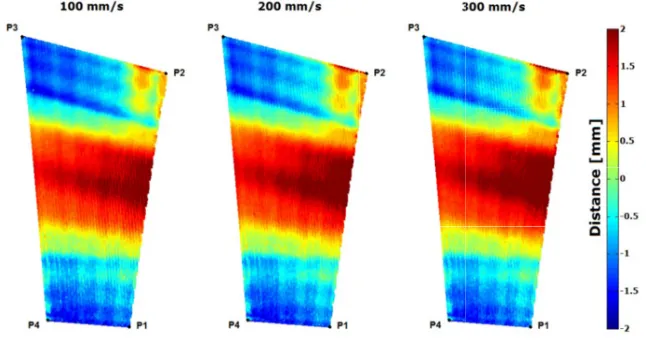
is common to many manufacturers. The prevalence of complex curved surfaces in the industry provides significant motivation for the use of 6 axis robots for deployment of NDT probes in these inspections. A new system for robot deployed ultrasonic inspection of composite aerospace components is presented. The key novelty of the approach is through the accommodation of flexible robotic trajectory planning, coordinated with the NDT data acquisition. Using a flexible approach in MATLAB, the authors have developed a high level custom toolbox that utilizes external control of an industrial 6 axis manipulator to achieve complex path planning and provide synchronization of the employed ultrasonic phase array inspection system. The developed software maintains a high level approach to the robot programming, in order to ease the programming complexity for an NDT inspection operator. Crucially the approach provides a pathway for a conditional programming approach and the capability for multiple robot control (a significant limitation in many current off-line programming applications). Ultrasonic and experimental data has been collected for the validation of the inspection technique. The path trajectory generation for a large, curved carbon-fiber-reinforced polymer (CFRP) aerofoil component has been proven and is presented. The path error relative to a raster-scan tool-path, suitable for ultrasonic phased array inspection, has been measured to be within ± 2mm over the 1.6 m2 area of the component surface.
INTRODUCTION
In civil aerospace manufacturing, the increasing deployment of composite materials demands a high integrity and traceability of NDT measurements. Modern components increasingly present challenging shapes and geometries for inspection. Using traditional manual inspection approaches produces a time-consuming bottleneck in industrial
production environments [1] and hence provides the fundamental motivation for increased automation.
The combined use of Modern Computer-Aided Design (CAD) and Computer-Aided Manufacturing (CAM) now allows large items to be produced easily from one piece of raw material (either through traditional subtractive
approaches, or with more recent additive manufacturing processes [2]). As a result, large components with complex
geometries are becoming very common in modern structures, and the aerospace industry is a typical field, where wide complex shaped parts are very frequently used. Moreover the use of composite materials, which are notoriously challenging to inspect [3], is becoming widespread in the construction of new generations of civilian aircraft. To cope with future demand projections for these operations, it is therefore essential to overcome the current NDT bottleneck.
suffer from inherent but different part to part spring-back out of the mould. This presents a significant challenge for precision NDT measurement deployment which must be flexible to accommodate these manufacturing issues. For these reasons, NDT inspection is often performed manually by technicians who typically have to move appropriate probes over the contour of the sample surfaces. Manual scanning requires trained technicians and results in a very slow inspection process for large samples. The repeatability of a test can be challenging in structures where complex setups are necessary to perform the inspection (e.g. orientation of the probe, constant standoff, etc.) [4]. While manual scanning may remain a valid approach around the edges of a structure, or the edges of holes in a structure, developing reliable automated solutions has become an industry priority to drive down inspection times. The fundamental aim of automation within the inspection process is to minimize downtimes due to the higher achievable speed, and in parallel to carry out 100% inspection coverage of the sample, including all edge areas.
Semi-automated inspection systems have been developed to overcome some of the shortcomings with manual inspection techniques, using both mobile and fixed robotic platforms. The use of linear manipulators and bridge designs has for a number of years provided the most stable conditions in terms of positioning accuracy [5, 6]. The use of these systems to inspect parts with noncomplex shapes (plates, cylinders or cones) is widespread; typically, they are specific machines which are used to inspect identically shaped and/or sized parts.
More recently, many manufacturers of industrial robots have produced robotic manipulators with excellent positional accuracy and repeatability. In the spectrum of robot manipulators, some modern robots have suitable attributes to develop automated NDT systems and cope with the challenging situations sought by the aerospace industry [7]. They present precise mechanical systems, the possibility to accurately calibrate each joint, and the ability to export positional data at frequencies up to 500Hz.
Some applications of 6-axis robotic arms in the NDT field have been published during the last few years and there is a growing interest in using such automation solutions with many manufacturers within the aerospace sector [1, 7-10]. Despite these previous efforts, there remain challenges to be addressed before fully automated NDT inspection of composite parts becomes commonplace. The key challenges include generation and in-process modification of the robot tool-path, high speed NDT data collection, integration of surface metrology measurements, and overall visualization of measurement results in a user friendly fashion. Collaborations driving this vision include the IntACom project, developed by TWI Technology Centre (Wales) on behalf of their sponsors over a period of 3 years. The project objective has been to achieve a fourfold increase in the throughput of aerospace components [1].
Additionally the UK RCNDE consortium conducts research into integration of metrology with NDT inspection [11, 12]. Both these consortia have identified the requirement for optimal tool path generation over complex curved surfaces. The current paper describes a novel approach to flexible robotic toolpath generation using a purposely developed MATLAB based path-planning software platform.
INVESTIGATED PATH PLANNING APPROACHES FOR NDT APPLICATIONS
Traditional Approach
Six-axis robotic arms have traditionally been used in production lines to move the robot end-effector from one position to a new position for repetitive assembly and welding operations. In this scenario, where the exact trajectory between two points in the space is not too important, the teach pendant of a robot is used to manually move the end-effector to the desired position and orientation at each stage of the robot task. Relevant robot configurations are recorded by the robot controller and a robot program is then written to command the robot to move through the recorded end-effector postures. More recently, accurate mechanical joints and control units have made industrial
robotic arms flexible and precise enough for finishing tasks in manufacturing operations [13]. Robotic manipulators
are highly complex systems and the trajectory accuracy of a machining tool has a huge impact on the quality and tolerances of the finished surfaces. As a result, many software environments have been developed by non-robot manufacturers, academic researchers and also by the robot manufacturers themselves, in order to help technicians
and engineers to program complex robot tasks [14]. The use of such software platforms to program robot movements
IntACom project using commercial robotic simulation and programming software. The chosen software was CENIT-Fast
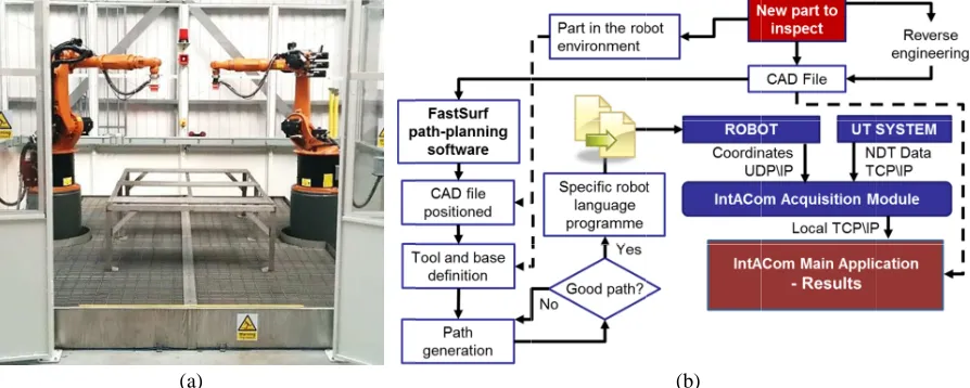
Figure 1 shows the IntACom inspection procedure
strong potential to give a great deal of flexibility for fast and eff However
instrument controller.
developed in the C# programming language, controls the GUI and behaves as a server application. The C++ language was chosen to write the
acquisition algorithms
through a local TCP/IP connection. The acquisition module connects Ethernet connection and to the
FastSurf ha achievement of the possible to list a series of
1.
Path-robot programming draws its origin from the need to use the advantageous flexibility of general Path-robotic manipulators to
result, many commercial software applications for off
incorporating lots of unnecessary functions for CAD/CAM purp abundance of functions, a tool
to some amendments, before fulfilling all the requirements for an effective NDT inspection. A number of problems are often present in the original path, being generated by software functions expressly developed for machining and production operations rather than for NDT tasks.
2. Significant complications exist when two or more robotic arms need to be synchronized
specific NDT ins
transducers: one emitter and one receiver; the receiver being placed on the opposite side of the component and facing the transmittin
not offer support for co
start or end points of complex paths) path, required for the UTT technique.
IntACom project using commercial robotic simulation and programming software. The chosen software was FastSurf [15], based on
Figure 1 shows the IntACom inspection procedure.
strong potential to give a great deal of flexibility for fast and eff it was necessary to develop
instruments, through encodin controller. The IntACom software
developed in the C# programming language, controls the GUI and behaves as a server application. The C++ language was chosen to write the
acquisition algorithms
through a local TCP/IP connection. The acquisition module connects Ethernet connection and to the
[image:3.595.74.521.275.454.2](a)
FIGURE 1. IntACom robot cell
FastSurf has supported the development of the IntACom robotic inspection system prototype and the achievement of the project
possible to list a series of
-planning for automated NDT inspections is a very specific
robot programming draws its origin from the need to use the advantageous flexibility of general robotic manipulators to replace the more traditional and usual machining tools (milling machines, lathes, etc.). As a result, many commercial software applications for off
incorporating lots of unnecessary functions for CAD/CAM purp abundance of functions, a tool
to some amendments, before fulfilling all the requirements for an effective NDT inspection. A number of blems are often present in the original path, being generated by software functions expressly developed for machining and production operations rather than for NDT tasks.
Significant complications exist when two or more robotic arms need to be synchronized specific NDT inspection. The Ultrasonic Through
transducers: one emitter and one receiver; the receiver being placed on the opposite side of the component and facing the transmittin
not offer support for co
start or end points of complex paths) path, required for the UTT technique.
IntACom project using commercial robotic simulation and programming software. The chosen software was , based on the Delmia platform
Figure 1 shows the IntACom robot cell and the Robot manipula
strong potential to give a great deal of flexibility for fast and eff t was necessary to develop
h encoding the ultrasound signals he IntACom software has a fundamental role
developed in the C# programming language, controls the GUI and behaves as a server application. The C++ language was chosen to write the
that run in a reliable manner.
through a local TCP/IP connection. The acquisition module connects Ethernet connection and to the UT instrument
(a)
IntACom robot cell
supported the development of the IntACom robotic inspection system prototype and the project objectives
possible to list a series of limitations
planning for automated NDT inspections is a very specific
robot programming draws its origin from the need to use the advantageous flexibility of general robotic replace the more traditional and usual machining tools (milling machines, lathes, etc.). As a result, many commercial software applications for off
incorporating lots of unnecessary functions for CAD/CAM purp
abundance of functions, a tool-path generated via a CAD/CAM commercial software usually has to be subjected to some amendments, before fulfilling all the requirements for an effective NDT inspection. A number of blems are often present in the original path, being generated by software functions expressly developed for machining and production operations rather than for NDT tasks.
Significant complications exist when two or more robotic arms need to be synchronized specific NDT inspection. The Ultrasonic Through
transducers: one emitter and one receiver; the receiver being placed on the opposite side of the component and facing the transmitting probe. Currently, m
not offer support for co-operating robots. FastS start or end points of complex paths)
path, required for the UTT technique.
IntACom project using commercial robotic simulation and programming software. The chosen software was Delmia platform
robot cell and the ipulators and modern U strong potential to give a great deal of flexibility for fast and eff
t was necessary to develop suitable software g the ultrasound signals
has a fundamental role
developed in the C# programming language, controls the GUI and behaves as a server application. The C++ language was chosen to write the acquisition module. Unlike C#, C++ is suitable to develop real
that run in a reliable manner.
through a local TCP/IP connection. The acquisition module connects UT instrument with a TCP/IP connection
IntACom robot cell (a) and schematic representation of the robotic inspection procedure
supported the development of the IntACom robotic inspection system prototype and the objectives. However, it has been noticed that there is
of current OLP software
planning for automated NDT inspections is a very specific
robot programming draws its origin from the need to use the advantageous flexibility of general robotic replace the more traditional and usual machining tools (milling machines, lathes, etc.). As a result, many commercial software applications for off
incorporating lots of unnecessary functions for CAD/CAM purp
path generated via a CAD/CAM commercial software usually has to be subjected to some amendments, before fulfilling all the requirements for an effective NDT inspection. A number of blems are often present in the original path, being generated by software functions expressly developed for machining and production operations rather than for NDT tasks.
Significant complications exist when two or more robotic arms need to be synchronized pection. The Ultrasonic Through
transducers: one emitter and one receiver; the receiver being placed on the opposite side of the component and Currently, many commercial pieces of software (e.g. Delcam and Mastercam) do operating robots. FastS
start or end points of complex paths), using digital I/O path, required for the UTT technique.
IntACom project using commercial robotic simulation and programming software. The chosen software was Delmia platform (Dassault Systems)
robot cell and the schematic representation of the modern Ultrasound
strong potential to give a great deal of flexibility for fast and eff software to integrate
g the ultrasound signals with the positional information coming has a fundamental role within the inspection procedure.
developed in the C# programming language, controls the GUI and behaves as a server application. The C++ acquisition module. Unlike C#, C++ is suitable to develop real
that run in a reliable manner. The main application receives data from the acquisition module through a local TCP/IP connection. The acquisition module connects
with a TCP/IP connection
chematic representation of the robotic inspection procedure
supported the development of the IntACom robotic inspection system prototype and the . However, it has been noticed that there is
of current OLP software:
planning for automated NDT inspections is a very specific
robot programming draws its origin from the need to use the advantageous flexibility of general robotic replace the more traditional and usual machining tools (milling machines, lathes, etc.). As a result, many commercial software applications for
off-incorporating lots of unnecessary functions for CAD/CAM purp
path generated via a CAD/CAM commercial software usually has to be subjected to some amendments, before fulfilling all the requirements for an effective NDT inspection. A number of blems are often present in the original path, being generated by software functions expressly developed for machining and production operations rather than for NDT tasks.
Significant complications exist when two or more robotic arms need to be synchronized
pection. The Ultrasonic Through-Transmission (UTT) technique, for example, uses two transducers: one emitter and one receiver; the receiver being placed on the opposite side of the component and any commercial pieces of software (e.g. Delcam and Mastercam) do operating robots. FastSurf allows partial synchronization of robotic movements
using digital I/O signals,
IntACom project using commercial robotic simulation and programming software. The chosen software was (Dassault Systems) [16].
schematic representation of the ltrasound Testing (UT)
strong potential to give a great deal of flexibility for fast and effective NDT inspections of large curved s to integrate the robot manipulators and the ultrasound with the positional information coming
within the inspection procedure.
developed in the C# programming language, controls the GUI and behaves as a server application. The C++ acquisition module. Unlike C#, C++ is suitable to develop real
The main application receives data from the acquisition module through a local TCP/IP connection. The acquisition module connects to the robot control
with a TCP/IP connection.
chematic representation of the robotic inspection procedure
supported the development of the IntACom robotic inspection system prototype and the . However, it has been noticed that there is
planning for automated NDT inspections is a very specific task. M
robot programming draws its origin from the need to use the advantageous flexibility of general robotic replace the more traditional and usual machining tools (milling machines, lathes, etc.). As a -line programming of robots are expensive tools, incorporating lots of unnecessary functions for CAD/CAM purposes and machining features. Despite the path generated via a CAD/CAM commercial software usually has to be subjected to some amendments, before fulfilling all the requirements for an effective NDT inspection. A number of blems are often present in the original path, being generated by software functions expressly developed for machining and production operations rather than for NDT tasks.
Significant complications exist when two or more robotic arms need to be synchronized
Transmission (UTT) technique, for example, uses two transducers: one emitter and one receiver; the receiver being placed on the opposite side of the component and any commercial pieces of software (e.g. Delcam and Mastercam) do
allows partial synchronization of robotic movements signals, but not full synchronisation over the complete IntACom project using commercial robotic simulation and programming software. The chosen software was
schematic representation of the originally developed Testing (UT) acquisition instruments ective NDT inspections of large curved s
the robot manipulators and the ultrasound with the positional information coming
within the inspection procedure.
developed in the C# programming language, controls the GUI and behaves as a server application. The C++ acquisition module. Unlike C#, C++ is suitable to develop real
The main application receives data from the acquisition module to the robot control
(b)
chematic representation of the robotic inspection procedure
supported the development of the IntACom robotic inspection system prototype and the . However, it has been noticed that there is still room for
task. Much commercial software for off robot programming draws its origin from the need to use the advantageous flexibility of general robotic
replace the more traditional and usual machining tools (milling machines, lathes, etc.). As a line programming of robots are expensive tools, oses and machining features. Despite the path generated via a CAD/CAM commercial software usually has to be subjected to some amendments, before fulfilling all the requirements for an effective NDT inspection. A number of blems are often present in the original path, being generated by software functions expressly developed for
Significant complications exist when two or more robotic arms need to be synchronized
Transmission (UTT) technique, for example, uses two transducers: one emitter and one receiver; the receiver being placed on the opposite side of the component and any commercial pieces of software (e.g. Delcam and Mastercam) do
allows partial synchronization of robotic movements but not full synchronisation over the complete IntACom project using commercial robotic simulation and programming software. The chosen software was
originally developed acquisition instruments ective NDT inspections of large curved s
the robot manipulators and the ultrasound with the positional information coming from th
within the inspection procedure. The main application, developed in the C# programming language, controls the GUI and behaves as a server application. The C++
acquisition module. Unlike C#, C++ is suitable to develop real
The main application receives data from the acquisition module to the robot controller through a
chematic representation of the robotic inspection procedure (b)
supported the development of the IntACom robotic inspection system prototype and the room for improvements
uch commercial software for off robot programming draws its origin from the need to use the advantageous flexibility of general robotic
replace the more traditional and usual machining tools (milling machines, lathes, etc.). As a line programming of robots are expensive tools, oses and machining features. Despite the path generated via a CAD/CAM commercial software usually has to be subjected to some amendments, before fulfilling all the requirements for an effective NDT inspection. A number of blems are often present in the original path, being generated by software functions expressly developed for
Significant complications exist when two or more robotic arms need to be synchronized in order to perform a Transmission (UTT) technique, for example, uses two transducers: one emitter and one receiver; the receiver being placed on the opposite side of the component and any commercial pieces of software (e.g. Delcam and Mastercam) do
allows partial synchronization of robotic movements but not full synchronisation over the complete IntACom project using commercial robotic simulation and programming software. The chosen software was
originally developed robotic acquisition instruments have a ective NDT inspections of large curved samples. the robot manipulators and the ultrasound from the robot The main application, developed in the C# programming language, controls the GUI and behaves as a server application. The C++ acquisition module. Unlike C#, C++ is suitable to develop real-time data The main application receives data from the acquisition module ler through a UDP/IP
(b).
supported the development of the IntACom robotic inspection system prototype and the improvements. It is
uch commercial software for off-line robot programming draws its origin from the need to use the advantageous flexibility of general robotic replace the more traditional and usual machining tools (milling machines, lathes, etc.). As a line programming of robots are expensive tools, oses and machining features. Despite the path generated via a CAD/CAM commercial software usually has to be subjected to some amendments, before fulfilling all the requirements for an effective NDT inspection. A number of blems are often present in the original path, being generated by software functions expressly developed for
3. Current OLP software lacks fundamental capability in conditional programming. Typically very specific code is generated for each toolpath, and changes to this pa
downloading a complete new path to the robot controller. NDT inspection often requires re particular area of interest of a sample in order to carry out more detailed investigation after an
This requirement places an additional demand of a more adaptive approach to the path planning that has the provision for conditional modification in response to externally measured data.
In summary, OLP is geared towards manufacturing a component.
transducers, and stored
position of acquisition; in other words, it is necessary to record the current position of the robot throughout the whole inspection time in order to encode the NDT data
encoders monitoring the position of each joint; they can inform about their position at regular time intervals lasting some milliseconds. The captured positions can be further interpolated to extrapolate t
collection time of each piece of NDT information. An external computer (separate to the robot controller) is generally required to process the robot positional data and perform
data.
New MATLAB
specifically address the current needs of robotic NDT overcomes
software is being developed around the specific needs of NDT inspections. this task is
through an feedback, it is c
piece of software capable of off control of robot movements. planning approach.
Using the MATLAB based path
creating specific robot language programs and be sent to the robot controller.
Current OLP software lacks fundamental capability in conditional programming. Typically very specific code is generated for each toolpath, and changes to this pa
downloading a complete new path to the robot controller. NDT inspection often requires re particular area of interest of a sample in order to carry out more detailed investigation after an
This requirement places an additional demand of a more adaptive approach to the path planning that has the provision for conditional modification in response to externally measured data.
In summary, OLP is geared towards manufacturing a
component. The result of an automated NDT inspection is a collection of digital data coming from one or more transducers, and stored
position of acquisition; in other words, it is necessary to record the current position of the robot throughout the whole inspection time in order to encode the NDT data
encoders monitoring the position of each joint; they can inform about their position at regular time intervals lasting some milliseconds. The captured positions can be further interpolated to extrapolate t
collection time of each piece of NDT information. An external computer (separate to the robot controller) is generally required to process the robot positional data and perform
D
ew MATLAB based path
specifically address the current needs of robotic NDT overcomes the deficiencies of existing off
software is being developed around the specific needs of NDT inspections. is the possibility to co
through an Ethernet connection. If the same computer is feedback, it is clear that a flexible and adaptive
piece of software capable of off control of robot movements. planning approach.
Using the MATLAB based path
creating specific robot language programs and be sent to the robot controller.
Current OLP software lacks fundamental capability in conditional programming. Typically very specific code is generated for each toolpath, and changes to this pa
downloading a complete new path to the robot controller. NDT inspection often requires re particular area of interest of a sample in order to carry out more detailed investigation after an
This requirement places an additional demand of a more adaptive approach to the path planning that has the provision for conditional modification in response to externally measured data.
In summary, OLP is geared towards manufacturing a
he result of an automated NDT inspection is a collection of digital data coming from one or more transducers, and stored in convenient ways
position of acquisition; in other words, it is necessary to record the current position of the robot throughout the whole inspection time in order to encode the NDT data
encoders monitoring the position of each joint; they can inform about their position at regular time intervals lasting some milliseconds. The captured positions can be further interpolated to extrapolate t
collection time of each piece of NDT information. An external computer (separate to the robot controller) is generally required to process the robot positional data and perform
Development of
based path-planning software specifically address the current needs of robotic NDT
the deficiencies of existing off
software is being developed around the specific needs of NDT inspections. the possibility to control industrial robots by
Ethernet connection. If the same computer is lear that a flexible and adaptive
[image:4.595.118.482.441.664.2]piece of software capable of off-line path planning and of outputting command coordinates suitable for external control of robot movements. Figure 2 shows t
FIGURE 2. Improved
Using the MATLAB based
path-creating specific robot language programs and be sent to the robot controller. The
Current OLP software lacks fundamental capability in conditional programming. Typically very specific code is generated for each toolpath, and changes to this pa
downloading a complete new path to the robot controller. NDT inspection often requires re particular area of interest of a sample in order to carry out more detailed investigation after an
This requirement places an additional demand of a more adaptive approach to the path planning that has the provision for conditional modification in response to externally measured data.
In summary, OLP is geared towards manufacturing a
he result of an automated NDT inspection is a collection of digital data coming from one or more in convenient ways. These data results are only meaningful when
position of acquisition; in other words, it is necessary to record the current position of the robot throughout the whole inspection time in order to encode the NDT data
encoders monitoring the position of each joint; they can inform about their position at regular time intervals lasting some milliseconds. The captured positions can be further interpolated to extrapolate t
collection time of each piece of NDT information. An external computer (separate to the robot controller) is generally required to process the robot positional data and perform
evelopment of MATLAB
planning software specifically address the current needs of robotic NDT
the deficiencies of existing off-line programming
software is being developed around the specific needs of NDT inspections. ntrol industrial robots by
Ethernet connection. If the same computer is
lear that a flexible and adaptive approach to path generation can
line path planning and of outputting command coordinates suitable for external Figure 2 shows the improved
Improved inspection procedure enabled by RoboNDT software.
-planning application instead of commercial software creating specific robot language programs and allows
The previously used
Current OLP software lacks fundamental capability in conditional programming. Typically very specific code is generated for each toolpath, and changes to this path due to changing operation conditions requires re downloading a complete new path to the robot controller. NDT inspection often requires re
particular area of interest of a sample in order to carry out more detailed investigation after an
This requirement places an additional demand of a more adaptive approach to the path planning that has the provision for conditional modification in response to externally measured data.
In summary, OLP is geared towards manufacturing applications where the task is the production of a specific he result of an automated NDT inspection is a collection of digital data coming from one or more
. These data results are only meaningful when
position of acquisition; in other words, it is necessary to record the current position of the robot throughout the whole inspection time in order to encode the NDT data [6]. Modern industrial robotic arms are equipped with encoders monitoring the position of each joint; they can inform about their position at regular time intervals lasting some milliseconds. The captured positions can be further interpolated to extrapolate t
collection time of each piece of NDT information. An external computer (separate to the robot controller) is generally required to process the robot positional data and perform
MATLAB Based
(herewith referred to as specifically address the current needs of robotic NDT. The aim is to obtain
ne programming.
software is being developed around the specific needs of NDT inspections.
ntrol industrial robots by an external computer communicating to the robot controllers Ethernet connection. If the same computer is used for controlling the robot path and receiving positional
approach to path generation can
line path planning and of outputting command coordinates suitable for external improved inspection procedure enabled by pursuing the new path
inspection procedure enabled by RoboNDT software.
planning application instead of commercial software
allows the generation of packets of command coordinates, suitable to previously used one-way UDP/IP communication between the acquisition Current OLP software lacks fundamental capability in conditional programming. Typically very specific code is th due to changing operation conditions requires re downloading a complete new path to the robot controller. NDT inspection often requires re
particular area of interest of a sample in order to carry out more detailed investigation after an
This requirement places an additional demand of a more adaptive approach to the path planning that has the provision for conditional modification in response to externally measured data.
pplications where the task is the production of a specific he result of an automated NDT inspection is a collection of digital data coming from one or more
. These data results are only meaningful when
position of acquisition; in other words, it is necessary to record the current position of the robot throughout the . Modern industrial robotic arms are equipped with encoders monitoring the position of each joint; they can inform about their position at regular time intervals lasting some milliseconds. The captured positions can be further interpolated to extrapolate t
collection time of each piece of NDT information. An external computer (separate to the robot controller) is generally required to process the robot positional data and perform synchronisation
ased Path-Planning
herewith referred to as RoboNDT . The aim is to obtain
. Unlike current commercial applications, the new software is being developed around the specific needs of NDT inspections.
an external computer communicating to the robot controllers used for controlling the robot path and receiving positional approach to path generation can
line path planning and of outputting command coordinates suitable for external inspection procedure enabled by pursuing the new path
inspection procedure enabled by RoboNDT software.
planning application instead of commercial software
the generation of packets of command coordinates, suitable to way UDP/IP communication between the acquisition Current OLP software lacks fundamental capability in conditional programming. Typically very specific code is th due to changing operation conditions requires re downloading a complete new path to the robot controller. NDT inspection often requires re
particular area of interest of a sample in order to carry out more detailed investigation after an
This requirement places an additional demand of a more adaptive approach to the path planning that has the provision for conditional modification in response to externally measured data.
pplications where the task is the production of a specific he result of an automated NDT inspection is a collection of digital data coming from one or more
. These data results are only meaningful when
position of acquisition; in other words, it is necessary to record the current position of the robot throughout the . Modern industrial robotic arms are equipped with encoders monitoring the position of each joint; they can inform about their position at regular time intervals lasting some milliseconds. The captured positions can be further interpolated to extrapolate the probe’s location at the collection time of each piece of NDT information. An external computer (separate to the robot controller) is synchronisation to the externally measured NDT
lanning Software
RoboNDT) was developed from scratch
. The aim is to obtain effective tool
Unlike current commercial applications, the new software is being developed around the specific needs of NDT inspections. The fundamental key point supporting
an external computer communicating to the robot controllers used for controlling the robot path and receiving positional approach to path generation can be achieved.
line path planning and of outputting command coordinates suitable for external inspection procedure enabled by pursuing the new path
inspection procedure enabled by RoboNDT software.
planning application instead of commercial software
the generation of packets of command coordinates, suitable to way UDP/IP communication between the acquisition Current OLP software lacks fundamental capability in conditional programming. Typically very specific code is th due to changing operation conditions requires re downloading a complete new path to the robot controller. NDT inspection often requires re-inspection of a particular area of interest of a sample in order to carry out more detailed investigation after an initial screening. This requirement places an additional demand of a more adaptive approach to the path planning that has the
pplications where the task is the production of a specific he result of an automated NDT inspection is a collection of digital data coming from one or more . These data results are only meaningful when merged with the precise position of acquisition; in other words, it is necessary to record the current position of the robot throughout the . Modern industrial robotic arms are equipped with encoders monitoring the position of each joint; they can inform about their position at regular time intervals lasting he probe’s location at the collection time of each piece of NDT information. An external computer (separate to the robot controller) is e externally measured NDT
oftware
was developed from scratch effective tool-path generation Unlike current commercial applications, the new
The fundamental key point supporting an external computer communicating to the robot controllers
used for controlling the robot path and receiving positional be achieved. RoboNDT aims to be a line path planning and of outputting command coordinates suitable for external inspection procedure enabled by pursuing the new path
inspection procedure enabled by RoboNDT software.
planning application instead of commercial software removes the necessity of the generation of packets of command coordinates, suitable to way UDP/IP communication between the acquisition Current OLP software lacks fundamental capability in conditional programming. Typically very specific code is th due to changing operation conditions requires
re-inspection of a initial screening. This requirement places an additional demand of a more adaptive approach to the path planning that has the
pplications where the task is the production of a specific he result of an automated NDT inspection is a collection of digital data coming from one or more merged with the precise position of acquisition; in other words, it is necessary to record the current position of the robot throughout the . Modern industrial robotic arms are equipped with encoders monitoring the position of each joint; they can inform about their position at regular time intervals lasting he probe’s location at the collection time of each piece of NDT information. An external computer (separate to the robot controller) is e externally measured NDT
was developed from scratch to path generation that Unlike current commercial applications, the new The fundamental key point supporting an external computer communicating to the robot controllers used for controlling the robot path and receiving positional RoboNDT aims to be a line path planning and of outputting command coordinates suitable for external inspection procedure enabled by pursuing the new
module and the robot manipulator is replaced by a two coordinates
acquisition module manages both the robot external control and the reception of feedback coordinates, it paves the way to the integration of metrology. Metrology sensors can easily be interfaced with the software platform
meaningful data for position error monitoring and/or real
between metrology sensors and the acquisition software can provide a viable pathway towards automatic recognition of the part to inspect a
RoboNDT software has been organized according to a modular architecture based on four modules: start path-planning, evaluation and output modu
user can import all the samples and parts of interest into the mounted to the robot manipulator can be set into the robot cells, complete
and the robot models. Any changes made to the robot models in the
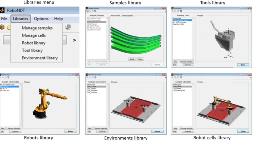
[image:5.595.86.512.300.538.2]Environments Library
Figure 3 shows screenshots of each one of the developed libraries.
The start
software can import Standard Tessellation Language (STL) CAD files
supported by the majority of the existing software packages; it is widely used for rapid prototyping and computer aided manufacturing.
selected robot cell. The calibration is an interactive procedure the part and in
coordinates, reported by
The path inspection tool
raster, segment
flexibility and customization according to the inspection needs module and the robot manipulator is replaced by a two coordinates, thus controlling the robot tool
acquisition module manages both the robot external control and the reception of feedback coordinates, it paves the way to the integration of metrology. Metrology sensors can easily be interfaced with the software platform
meaningful data for position error monitoring and/or real
between metrology sensors and the acquisition software can provide a viable pathway towards automatic recognition of the part to inspect and the assessment of its position within the robot working envelope.
RoboNDT software has been organized according to a modular architecture based on four modules: start planning, evaluation and output modu
user can import all the samples and parts of interest into the mounted to the robot manipulator can be set into the robot cells, complete with
and the robot models. Any changes made to the robot models in the
Environments Library
Figure 3 shows screenshots of each one of the developed libraries.
start-up module
software can import Standard Tessellation Language (STL) CAD files
supported by the majority of the existing software packages; it is widely used for rapid prototyping and computer aided manufacturing. The start
selected robot cell. The calibration is an interactive procedure the part and insert their
coordinates, reported by
path-planning module
inspection tool-path for each given surface of the part of interest. Three main tool
segment and single
flexibility and customization according to the inspection needs module and the robot manipulator is replaced by a two
, thus controlling the robot tool
acquisition module manages both the robot external control and the reception of feedback coordinates, it paves the way to the integration of metrology. Metrology sensors can easily be interfaced with the software platform
meaningful data for position error monitoring and/or real
between metrology sensors and the acquisition software can provide a viable pathway towards automatic recognition nd the assessment of its position within the robot working envelope.
RoboNDT software has been organized according to a modular architecture based on four modules: start planning, evaluation and output modu
user can import all the samples and parts of interest into the mounted to the robot manipulator can be set into the
with environment
and the robot models. Any changes made to the robot models in the
are automatically transferred to the assembled robot cells defined in the Figure 3 shows screenshots of each one of the developed libraries.
FIGURE
module of the software is responsible for setting the scene of the path
software can import Standard Tessellation Language (STL) CAD files
supported by the majority of the existing software packages; it is widely used for rapid prototyping and computer The start-up mod
selected robot cell. The calibration is an interactive procedure sert their positions by jogging the rob coordinates, reported by the robot teach pendant
planning module is the core of the software. It contains the necessary algorithms to generate the desired
path for each given surface of the part of interest. Three main tool
single point scan
flexibility and customization according to the inspection needs module and the robot manipulator is replaced by a two
, thus controlling the robot tool-path,
acquisition module manages both the robot external control and the reception of feedback coordinates, it paves the way to the integration of metrology. Metrology sensors can easily be interfaced with the software platform
meaningful data for position error monitoring and/or real
between metrology sensors and the acquisition software can provide a viable pathway towards automatic recognition nd the assessment of its position within the robot working envelope.
RoboNDT software has been organized according to a modular architecture based on four modules: start planning, evaluation and output module. For the sake of flexibility, the sof
user can import all the samples and parts of interest into the mounted to the robot manipulator can be set into the
environment parts and robot manipulators. Separate libraries exist for the environments and the robot models. Any changes made to the robot models in the
are automatically transferred to the assembled robot cells defined in the Figure 3 shows screenshots of each one of the developed libraries.
FIGURE 3. Screenshots of the
of the software is responsible for setting the scene of the path software can import Standard Tessellation Language (STL) CAD files
supported by the majority of the existing software packages; it is widely used for rapid prototyping and computer up module allows the calibration of the part of interest within the
selected robot cell. The calibration is an interactive procedure by jogging the rob
robot teach pendant, are transferred into the start
the core of the software. It contains the necessary algorithms to generate the desired path for each given surface of the part of interest. Three main tool
point scan. Each path t
flexibility and customization according to the inspection needs
module and the robot manipulator is replaced by a two-way connection that allows streaming of the command path, and reception of
acquisition module manages both the robot external control and the reception of feedback coordinates, it paves the way to the integration of metrology. Metrology sensors can easily be interfaced with the software platform
meaningful data for position error monitoring and/or real-time path correction.
between metrology sensors and the acquisition software can provide a viable pathway towards automatic recognition nd the assessment of its position within the robot working envelope.
RoboNDT software has been organized according to a modular architecture based on four modules: start le. For the sake of flexibility, the sof
user can import all the samples and parts of interest into the Samples Library mounted to the robot manipulator can be set into the Tools Library
and robot manipulators. Separate libraries exist for the environments and the robot models. Any changes made to the robot models in the
are automatically transferred to the assembled robot cells defined in the Figure 3 shows screenshots of each one of the developed libraries.
Screenshots of the
of the software is responsible for setting the scene of the path software can import Standard Tessellation Language (STL) CAD files
supported by the majority of the existing software packages; it is widely used for rapid prototyping and computer allows the calibration of the part of interest within the
selected robot cell. The calibration is an interactive procedure; t
by jogging the robot Tool Centre Point (TCP) to the real point , are transferred into the start
the core of the software. It contains the necessary algorithms to generate the desired path for each given surface of the part of interest. Three main tool
Each path type has several characteristic settings that allow a good level of flexibility and customization according to the inspection needs (scanning step, speed, offsets, etc…)
way connection that allows streaming of the command and reception of robot positi
acquisition module manages both the robot external control and the reception of feedback coordinates, it paves the way to the integration of metrology. Metrology sensors can easily be interfaced with the software platform
time path correction.
between metrology sensors and the acquisition software can provide a viable pathway towards automatic recognition nd the assessment of its position within the robot working envelope.
RoboNDT software has been organized according to a modular architecture based on four modules: start le. For the sake of flexibility, the sof
Samples Library
Tools Library. The Robot Cell Library
and robot manipulators. Separate libraries exist for the environments and the robot models. Any changes made to the robot models in the Robots Library
are automatically transferred to the assembled robot cells defined in the Figure 3 shows screenshots of each one of the developed libraries.
Screenshots of the developed libraries
of the software is responsible for setting the scene of the path
software can import Standard Tessellation Language (STL) CAD files [17]. The STL format was chosen because it is
supported by the majority of the existing software packages; it is widely used for rapid prototyping and computer allows the calibration of the part of interest within the
; the operator
ot Tool Centre Point (TCP) to the real point , are transferred into the
start-the core of start-the software. It contains start-the necessary algorithms to generate start-the desired path for each given surface of the part of interest. Three main tool
ype has several characteristic settings that allow a good level of (scanning step, speed, offsets, etc…)
way connection that allows streaming of the command positional feedback.
acquisition module manages both the robot external control and the reception of feedback coordinates, it paves the way to the integration of metrology. Metrology sensors can easily be interfaced with the software platform
time path correction. Moreover, the communication between metrology sensors and the acquisition software can provide a viable pathway towards automatic recognition
nd the assessment of its position within the robot working envelope.
RoboNDT software has been organized according to a modular architecture based on four modules: start le. For the sake of flexibility, the software contains five libraries. The
Samples Library. The probes, sensors and tools to be Robot Cell Library
and robot manipulators. Separate libraries exist for the environments
Robots Library or to the environments in the
are automatically transferred to the assembled robot cells defined in the
developed libraries.
of the software is responsible for setting the scene of the path
. The STL format was chosen because it is supported by the majority of the existing software packages; it is widely used for rapid prototyping and computer
allows the calibration of the part of interest within the
can select up to 10 reference points of ot Tool Centre Point (TCP) to the real point
-up module.
the core of the software. It contains the necessary algorithms to generate the desired path for each given surface of the part of interest. Three main tool-path types
ype has several characteristic settings that allow a good level of (scanning step, speed, offsets, etc…)
way connection that allows streaming of the command onal feedback. Since the upgraded acquisition module manages both the robot external control and the reception of feedback coordinates, it paves the way to the integration of metrology. Metrology sensors can easily be interfaced with the software platform
Moreover, the communication between metrology sensors and the acquisition software can provide a viable pathway towards automatic recognition
RoboNDT software has been organized according to a modular architecture based on four modules: start tware contains five libraries. The . The probes, sensors and tools to be
Robot Cell Library can contain mu
and robot manipulators. Separate libraries exist for the environments or to the environments in the are automatically transferred to the assembled robot cells defined in the Robot Cells Library
of the software is responsible for setting the scene of the path-planning project. . The STL format was chosen because it is supported by the majority of the existing software packages; it is widely used for rapid prototyping and computer
allows the calibration of the part of interest within the virtual model of the select up to 10 reference points of ot Tool Centre Point (TCP) to the real points. The relative
the core of the software. It contains the necessary algorithms to generate the desired path types are being implemented: ype has several characteristic settings that allow a good level of
(scanning step, speed, offsets, etc…).
way connection that allows streaming of the command Since the upgraded acquisition module manages both the robot external control and the reception of feedback coordinates, it paves the way to the integration of metrology. Metrology sensors can easily be interfaced with the software platform to obtain Moreover, the communication between metrology sensors and the acquisition software can provide a viable pathway towards automatic recognition
RoboNDT software has been organized according to a modular architecture based on four modules: start-up, tware contains five libraries. The . The probes, sensors and tools to be can contain multiple and robot manipulators. Separate libraries exist for the environments or to the environments in the
Robot Cells Library.
planning project. The . The STL format was chosen because it is supported by the majority of the existing software packages; it is widely used for rapid prototyping and
computer-virtual model of the select up to 10 reference points of s. The relative
The evaluation module other CAD c
robotic arms had initially been based on open by the University
KCT. The open
point within its working envelope unsuitable
kinematics
three snapshots of the recorded simulation video inspection too
of 100 mm/s.
Finally, the output module format are generated for each tool execute the generated tool
approach the starting point of the inspection and
each line merely contains 6 coordinates (x, y, z, A, B, C) to drive the r
control unit, shown by the schema given in Figure 2, imports both files and sends the comman controller.
The new path The insertion
behind multiple robot synchronization. from the same external ser
minimum. The maximum misalignment would interpolation cycle. For
100mm/s, the maximum p
commercial solutions that use digital I/O signals for synchronization purposes.
It is usual for NDT operators to do situations, generating specific tool
would be time consuming and not very practical. A MATLAB based
evaluation module
other CAD components included in the robotic arms had initially been based on open by the University of Siena (Italy) in 2011
The open-source code does not allow t within its working envelope
unsuitable for use in the new software application that has a target kinematics function, based on a geometric approach
three snapshots of the recorded simulation video inspection tool-path for
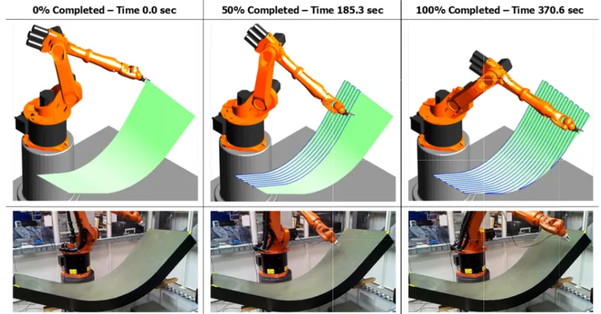
[image:6.595.85.507.240.461.2]of 100 mm/s. The toolpath simulation of RoboNDT allows accurate time approximation of scanning time.
FIGURE 4. Snapshots of
Finally, the output module are generated for each tool execute the generated tool
approach the starting point of the inspection and
each line merely contains 6 coordinates (x, y, z, A, B, C) to drive the r
control unit, shown by the schema given in Figure 2, imports both files and sends the comman controller.
The new path-planning approach paves the way to The insertion of multiple packets
behind multiple robot synchronization. from the same external ser
minimum. The maximum misalignment would interpolation cycle. For
mm/s, the maximum p
commercial solutions that use digital I/O signals for synchronization purposes.
It is usual for NDT operators to do situations, generating specific tool
would be time consuming and not very practical. A MATLAB based
evaluation module provides a full simulation capability of the programmed robot p
omponents included in the robotic arms had initially been based on open
of Siena (Italy) in 2011 source code does not allow t within its working envelope
for use in the new software application that has a target based on a geometric approach
three snapshots of the recorded simulation video path for a given datum surface. The tool
The toolpath simulation of RoboNDT allows accurate time approximation of scanning time.
Snapshots of the simulation video and of the real inspection tool
Finally, the output module has been are generated for each tool-execute the generated tool-path; the
approach the starting point of the inspection and
each line merely contains 6 coordinates (x, y, z, A, B, C) to drive the r
control unit, shown by the schema given in Figure 2, imports both files and sends the comman
planning approach paves the way to of multiple packets of coordinates behind multiple robot synchronization.
from the same external server computer enables the path synchronization mismatch to be maintained minimum. The maximum misalignment would
interpolation cycle. For example, for
mm/s, the maximum path mismatch would be equal to
commercial solutions that use digital I/O signals for synchronization purposes.
It is usual for NDT operators to do
situations, generating specific tool-paths for all the areas of interest through commercial path would be time consuming and not very practical. A MATLAB based
provides a full simulation capability of the programmed robot p omponents included in the robot cell. The
robotic arms had initially been based on open-source MATLAB code, the KUKA Control Toolbox (KCT) produced
of Siena (Italy) in 2011 [18]. However, a fundamental problem was observed with the usage of the
source code does not allow the selection
t within its working envelope in 8 different configurations for use in the new software application that has a target
based on a geometric approach three snapshots of the recorded simulation video
atum surface. The tool
The toolpath simulation of RoboNDT allows accurate time approximation of scanning time.
the simulation video and of the real inspection tool of the example target surface
has been developed to output the result -path. The first
; the second file contain approach the starting point of the inspection and retract from
each line merely contains 6 coordinates (x, y, z, A, B, C) to drive the r
control unit, shown by the schema given in Figure 2, imports both files and sends the comman
planning approach paves the way to of coordinates behind multiple robot synchronization. Sending command
ver computer enables the path synchronization mismatch to be maintained minimum. The maximum misalignment would
for robots running ath mismatch would be equal to
commercial solutions that use digital I/O signals for synchronization purposes.
It is usual for NDT operators to double check some suspect areas of a part, after an initial inspection. For such paths for all the areas of interest through commercial path
would be time consuming and not very practical. A MATLAB based
provides a full simulation capability of the programmed robot p
cell. The implementation of the full inverse kinematic model of the source MATLAB code, the KUKA Control Toolbox (KCT) produced However, a fundamental problem was observed with the usage of the the selection of the robot configuration (a six
in 8 different configurations for use in the new software application that has a target
based on a geometric approach, was therefore
three snapshots of the recorded simulation video acquired from the RoboNDT software atum surface. The tool-path is
The toolpath simulation of RoboNDT allows accurate time approximation of scanning time.
the simulation video and of the real inspection tool of the example target surface
developed to output the result
he first file contains all command coordinates contains the necessary
retract from the endpoint. These two files have very simple syntax; each line merely contains 6 coordinates (x, y, z, A, B, C) to drive the r
control unit, shown by the schema given in Figure 2, imports both files and sends the comman
planning approach paves the way to supporting inspection techniques that require multiple rob in each line of the first command file can be
Sending command coordinates
ver computer enables the path synchronization mismatch to be maintained minimum. The maximum misalignment would remain within the distance covered by the robots in a single
running in a 12
ath mismatch would be equal to 1.2 mm. This worst case scenario is much improved over commercial solutions that use digital I/O signals for synchronization purposes.
uble check some suspect areas of a part, after an initial inspection. For such paths for all the areas of interest through commercial path
would be time consuming and not very practical. A MATLAB based
provides a full simulation capability of the programmed robot p
implementation of the full inverse kinematic model of the source MATLAB code, the KUKA Control Toolbox (KCT) produced However, a fundamental problem was observed with the usage of the
the robot configuration (a six in 8 different configurations). This inconvenience for use in the new software application that has a target to be as flexible as
therefore developed and implemented acquired from the RoboNDT software
path is a raster scan with 50 mm pitch, executed at a speed The toolpath simulation of RoboNDT allows accurate time approximation of scanning time.
the simulation video and of the real inspection tool of the example target surface.
developed to output the results of the computations contains all command coordinates
necessary points to set the initial and final motion to the endpoint. These two files have very simple syntax; each line merely contains 6 coordinates (x, y, z, A, B, C) to drive the robotic arm to a spe
control unit, shown by the schema given in Figure 2, imports both files and sends the comman
supporting inspection techniques that require multiple rob ine of the first command file can be
coordinates simultaneously to multiple robot controllers ver computer enables the path synchronization mismatch to be maintained
within the distance covered by the robots in a single 12 milliseconds in
mm. This worst case scenario is much improved over commercial solutions that use digital I/O signals for synchronization purposes.
uble check some suspect areas of a part, after an initial inspection. For such paths for all the areas of interest through commercial path
would be time consuming and not very practical. A MATLAB based path
provides a full simulation capability of the programmed robot p
implementation of the full inverse kinematic model of the source MATLAB code, the KUKA Control Toolbox (KCT) produced However, a fundamental problem was observed with the usage of the
the robot configuration (a six inconvenience to be as flexible as
oped and implemented acquired from the RoboNDT software
a raster scan with 50 mm pitch, executed at a speed The toolpath simulation of RoboNDT allows accurate time approximation of scanning time.
the simulation video and of the real inspection tool-path, for the datum surfac
f the computations contains all command coordinates
points to set the initial and final motion to the endpoint. These two files have very simple syntax;
obotic arm to a spe control unit, shown by the schema given in Figure 2, imports both files and sends the comman
supporting inspection techniques that require multiple rob ine of the first command file can be
simultaneously to multiple robot controllers ver computer enables the path synchronization mismatch to be maintained
within the distance covered by the robots in a single onds interpolation cycle and moving at mm. This worst case scenario is much improved over commercial solutions that use digital I/O signals for synchronization purposes.
uble check some suspect areas of a part, after an initial inspection. For such paths for all the areas of interest through commercial path
path-planning module has been purposely provides a full simulation capability of the programmed robot path together with any implementation of the full inverse kinematic model of the source MATLAB code, the KUKA Control Toolbox (KCT) produced However, a fundamental problem was observed with the usage of the
the robot configuration (a six-axis robot can reach made the KCT function
possible. A new oped and implemented. Figure
acquired from the RoboNDT software and of the real robot a raster scan with 50 mm pitch, executed at a speed The toolpath simulation of RoboNDT allows accurate time approximation of scanning time.
path, for the datum surface
f the computations. Two text files contains all command coordinates that the robot needs
points to set the initial and final motion to the endpoint. These two files have very simple syntax; obotic arm to a specific pose. The external control unit, shown by the schema given in Figure 2, imports both files and sends the command data to the robot
supporting inspection techniques that require multiple rob ine of the first command file can become the principle
simultaneously to multiple robot controllers ver computer enables the path synchronization mismatch to be maintained
within the distance covered by the robots in a single terpolation cycle and moving at mm. This worst case scenario is much improved over
uble check some suspect areas of a part, after an initial inspection. For such paths for all the areas of interest through commercial path-planning software planning module has been purposely ath together with any implementation of the full inverse kinematic model of the source MATLAB code, the KUKA Control Toolbox (KCT) produced However, a fundamental problem was observed with the usage of the axis robot can reach any made the KCT function new inverse Figure 4 presents and of the real robot a raster scan with 50 mm pitch, executed at a speed The toolpath simulation of RoboNDT allows accurate time approximation of scanning time.
e
text files in ASCII that the robot needs to points to set the initial and final motion to the endpoint. These two files have very simple syntax; cific pose. The external d data to the robot
supporting inspection techniques that require multiple robots. the principle simultaneously to multiple robot controllers ver computer enables the path synchronization mismatch to be maintained to the within the distance covered by the robots in a single terpolation cycle and moving at mm. This worst case scenario is much improved over