Bauer, Ralf R. and Brown, Gordon G. and Lì, Lì L. and Uttamchandani,
Deepak G. (2013) A novel continuously variable angular vertical
comb-drive with application in scanning micromirror. In: 2013 IEEE 26th
International Conference on Micro Electro Mechanical Systems (MEMS).
IEEE, 9781467356558, pp. 528-531. ,
http://dx.doi.org/10.1109/MEMSYS.2013.6474295
This version is available at https://strathprints.strath.ac.uk/46197/
Strathprints is designed to allow users to access the research output of the University of Strathclyde. Unless otherwise explicitly stated on the manuscript, Copyright © and Moral Rights for the papers on this site are retained by the individual authors and/or other copyright owners. Please check the manuscript for details of any other licences that may have been applied. You may not engage in further distribution of the material for any profitmaking activities or any commercial gain. You may freely distribute both the url (https://strathprints.strath.ac.uk/) and the content of this paper for research or private study, educational, or not-for-profit purposes without prior permission or charge.
Any correspondence concerning this service should be sent to the Strathprints administrator:
The Strathprints institutional repository (https://strathprints.strath.ac.uk) is a digital archive of University of Strathclyde research outputs. It has been developed to disseminate open access research outputs, expose data about those outputs, and enable the
A NOVEL CONTINUOUSLY VARIABLE ANGULAR VERTICAL
COMB-DRIVE WITH APPLICATION IN SCANNING MICROMIRROR
Ralf Bauer, Gordon Brown, Li Li, and Deepak Uttamchandani
Centre for Microsystems and Photonics, University of Strathclyde, Glasgow, UK
ABSTRACT
An angular vertical comb-drive (AVC) with electrically controllable initial comb-offset is presented in the context of a single crystalline silicon scanning micromirror. The electrothermal actuated control of the variable offset is used to investigate the influence of the initial comb offset on the dynamic resonance behavior of the scanning mirror. With possible maximum vertical comb-offsets between 10 m and 5 m a higher dynamic mirror scan angle at the mechanical resonance frequency of 6 kHz is found for higher initial offsets. The same behavior of higher scan angles for higher offsets is also shown when mechanically controlling the initial comb-offset including negative offset values and offsets close to 0 m.
INTRODUCTION
Electrostatic actuated angular vertical comb-drives (AVCs) have comb-electrodes which do not lie in a single plane, therefore the “fixed” and “moving” combs have a non-zero cross-over angle. In the case of static mirror displacements the theoretical and experimental behavior of AVCs driven by DC voltages has been studied previously investigating amongst others the influence of comb offsets and comb-finger length on the achievable static scan angles [1-5]. Studies of the behavior of AVCs driven by AC voltages without change of the initial comb cross-over angle have also been reported [6, 7], with this type of actuator continuing to be applied, for example in scanning micromirrors [8-10]. We are not aware of any study investigating the influence of the initial comb cross-over angle of an AVC on its dynamic behavior. To investigate this effect we have designed and fabricated a novel hybrid electrode design for AVC actuators combining electrothermal bimorph out-of-plane actuators with the fixed combs of the electrostatic comb-drive. The key feature of the design is the ability to electrically adjust the comb-offset and consequently the cross-over angle of the AVC. This variable angle AVC has been coupled to a micromirror to produce a microscanner operated at its mechanical resonance of around 6 kHz. By analyzing the optical scan pattern, the dynamic characteristics of the AVC for different values of comb-offsets can be measured.
DESIGN AND FABRICATION
The layout of the 700 m diameter microscanner is shown in Figure 1. The 13 comb-pairs of the single-sided AVC used for exciting the scanning movement have a finger overlap length of 153 m with a lateral gap of 6 m. The mirror surface is connected via a 25 m wide frame and two sets of rectangular torsion springs to the substrate, with the longer ones with a length of 744 m and width of 18 m mainly determining the resonance frequency.
Figure 1: Layout of the AVC scanning micromirror
[image:2.595.308.538.154.294.2]including layer structure and comb-offset view
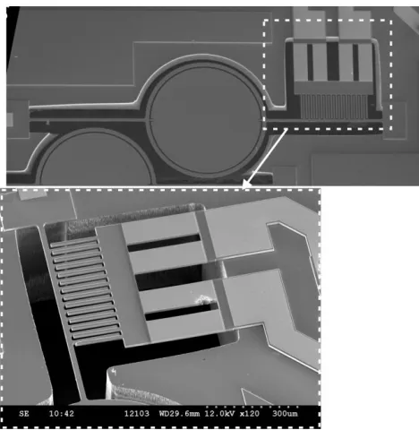
Figure 2: SEM of the scanning mirror device and the AVC actuator structure including the electrothermal actuator connections to the fixed combs
[image:2.595.307.541.348.588.2]and to continuously change the initial comb-offset, four electrothermal bimorph actuators are included in the released anchor connections i.e. the fixed part of the AVC (see Figure 2). The bimorph actuators consist of a 1.1 m gold coating on the doped silicon device layer, and generate a downward bending of the fixed part of the AVC (due to Joule heating) when a DC voltage is applied.
THERMAL
ACTUATOR
SIMULATION
AND CHARACTERIZATION
The initial position and behavior for an applied DC voltage between the two isolated anchors of the fixed comb-structure is simulated using the commercially available FEM software CoventorWare. The simulation layout includes the anchors to the substrate, the bimorph actuators, a cross-connector creating the current path between the 2 sets of parallel bimorph actuators and the fixed comb-fingers. The applied voltage will create an electrical current through the bimorph actuators and cross-connection which leads to Joule heating in these parts. Thermal expansion in the bimorph actuators will lead to a downward bending movement due to higher thermal expansion of the upper gold layer.
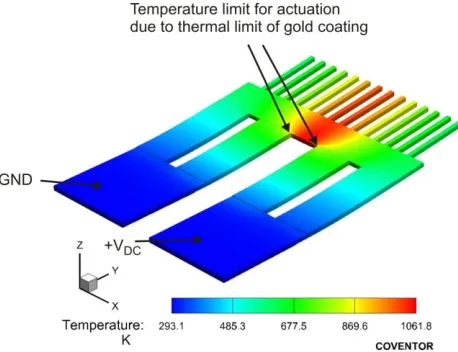
The simulation of the initial position after fabrication shows a maximum vertical offset of the comb-tips of 10.8 m, related to the initial stress in the actuators due to the non-homogeneous doping concentration and inter-layer stresses between the gold and silicon. When applying an electrical DC power from 0 mW to 593 mW the maximum vertical comb-tip offset z1 can be continuously changed from 10.8 m to 5.0 m (see Figure 5). The maximum applied DC voltage is limited by the temperature in the gold layer to avoid thermal damage to the actuators. A simulated maximum temperature of 1062 K leads to the maximum comb-tip offset change of 5.8 m. The simulated temperature distribution in the actuator for this case is shown in Figure 3, with the corresponding vertical displacement of the whole actuator shown in Figure 4.
The comb-offsets of the fixed and moveable combs of the actuators are experimentally characterized after fabrication by using a Veeco NT1100 optical profiler. The offset is controlled by applying a DC voltage between the anchor connections and simultaneously measuring the applied current and voltage over the device. Both the maximum vertical offset at the tip of the fixed combs z1 and the offset at the tip of the moving combs are determined with the results shown in Figure 5. The trend of the experimentally determined change of offsets match the trend of the FEM simulations with a maximum measured offset z1 of 10.4 m without actuation and of 4.9 m when actuated with a DC voltage of 1.5 V, which is equivalent to an applied electrical power of 510 mW. A complete in-plane alignment cannot be achieved with electrical actuation due to the thermal restrictions of the used bimorph actuators.
SCANNER CHARACTERIZATION AND
DEPENDENCY ON INITIAL OFFSET
[image:3.595.308.537.53.229.2]To evaluate the influence of the initial comb-offset on the dynamic behavior of the scanning micromirror, the
Figure 3: FEM simulation of the temperature distribution of the AVC actuator at the maximum position with an applied DC power of 593 mW
Figure 4: FEM simulation of the electrothermal offset change of the AVC actuator at the maximum position with an applied DC power of 593 mW
Figure 5: Simulated and measured initial comb-offset change due to Joule-heating of the bimorph fixed-combs anchors.
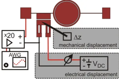
[image:3.595.306.543.286.458.2] [image:3.595.305.542.525.712.2]Figure 6: Actuation diagram for the electrical and mechanical change of the comb-offset including the resonance actuation with an Arbitrary Waveform Generator (AWG)
mirror is actuated at its torsional resonance using a 80 volts offset square-wave signal, while electrically or mechanically changing the initial comb-offset (see Figure 6). For the electrical displacement a DC power supply is connected to the terminals of the fixed combs with the ground path sharing the fixed-comb anchor connection with the ground port of the applied AC square-wave signal.
The AC signal is generated using an arbitrary waveform generator in combination with a x20 amplifier. The whole setup is mounted underneath a Veeco NT1100 white light interferometer profiler to evaluate the initial comb-offset for both the electrical and mechanical displacement before and after the AC actuation. The mechanical displacement is carried out using the vertical displacement of a needle pressing down on the fixed comb-anchors. The displacement is controlled using a vertical micrometer stage with the applied offset being monitored by the Veeco optical profiler. The resulting frequency response curves for actuation around the mechanical torsion resonance frequency are shown in Figure 7 and Figure 8 for the electrical and mechanical offset change respectively. The maximum total optical scan angle (TOSA) without changing the comb-offset is 21° at 6005 Hz which reduces to 14° at 6010 Hz when applying a DC voltage of 1.5 V to the bimorph actuators to reduce the initial maximum comb-offset to 4.9 m. A similar behavior of a reduction of the maximum TOSA with smaller comb-crossover angles occurs for the mechanical offset change. For comb-offsets close to 0 m only a low TOSA of 2° is achieved with again increasing maximum scan angles when the fixed combs are displaced below the moving combs initial position, creating negative offset values. The comb overlap cannot reach a perfect in-plane configuration due to the acting point of the mechanical displacement which leads to a positive z1 and negative z2 offset, which may be the reason for the very limited response of the 0.5 m displacement.
CONCLUSION
In summary, a novel approach for continuously tuning the initial comb-offset (and angle) of an AVC geometry has been experimentally evaluated. Higher initial comb-offsets produce higher scan angles with a lowering
Figure 7: Dynamic frequency response of scanning mirror with electrical change of initial comb-offset
Figure 8: Dynamic frequency response of scanning mirror with mechanical change of initial comb-offset
of the resonance frequency. An increase in the initial maximum comb-offset from 5 m to 10 m resulted in a 50% increase of the angular response for an offset square-wave actuation with 80 Vp-p. A theoretical model for the behavior is currently being built and will be presented alongside the experimental results.
ACKNOWLEDGMENTS
RB acknowledges support from the Scottish Founding Council (SFC)
REFERENCES
[1] Y. Eun, H. Na, J. Choi, J. Lee, and J. Kim, “Angular
vertical comb actuators assembled on-chip using in-plane electrothermal actuators and latching
[image:4.595.72.268.55.186.2] [image:4.595.305.541.303.485.2][2] M. Fujino, P. R. Patterson, H. Nguyen, W.
Piyawattanametha, and M. C. Wu, “Monolithically
Cascaded Micromirror Pair Driven by Angular Vertical Combs for Two-Axis Scanning,” IEEE Journal of Selected Topics in Quantum Electronics, vol. 10, no. 3, pp. 492–497, May 2004.
[3] D. Hah, P. R. Patterson, H. D. Nguyen, H. Toshiyoshi,
and M. C. Wu, “Theory and Experiments of Angular
Vertical Comb-Drive Actuators for Scanning
Micromirrors,” IEEE Journal of Selected Topics in Quantum Electronics, vol. 10, no. 3, pp. 505–513, May 2004.
[4] Y. K. Hong and R. R. a. Syms, “Dynamic Response
Modeling of MEMS Micromirror Corner Cube
Reflectors With Angular Vertical Combdrives,”
Journal of Lightwave Technology, vol. 25, no. 2, pp. 472–480, Feb. 2007.
[5] J. Kim, H. Choo, L. Lin, and R. S. Muller,
“Microfabricated Torsional Actuators Using
Self-Aligned Plastic Deformation of Silicon,” Journal of Microelectromechanical Systems, vol. 15, no. 3, pp. 553–562, Jun. 2006.
[6] J.-I. Lee, S. Park, Y. Eun, B. Jeong, and J. Kim,
“Resonant Frequency Tuning of Torsional
Microscanner by Mechanical Restriction using
MEMS Actuator,” 2009 IEEE 22nd International
Conference on Micro Electro Mechanical Systems, no. c, pp. 164–167, Jan. 2009.
[7] W. Piyawattanametha, P. R. Patterson, D. Hah, H.
Toshiyoshi, and M. C. Wu, “Surface- and bulk- micromachined two-dimensional scanner driven by
angular vertical comb actuators,” Journal of
Microelectromechanical Systems, vol. 14, no. 6, pp. 1329–1338, Dec. 2005.
[8] T. Sandner, D. Jung, D. Kallweit, T. Grasshoff, and H.
Schenk, “Microscanner with vertical out of plane combdrive,” in 16th International Conference on
Optical MEMS and Nanophotonics, 2011, pp. 33–34.
[9] H. Xie, Y. Pan, and G. K. Fedder, “A CMOS-MEMS
mirror with curled-hinge comb drives,” Journal of Microelectromechanical Systems, vol. 12, no. 4, pp. 450–457, Aug. 2003.
[10]J.-L. Yeh, C.-Y. Hui, and N. C. Tien, “Electrostatic model for an asymmetric combdrive,” Journal of Microelectromechanical Systems, vol. 9, no. 1, pp. 126–135, Mar. 2000.
CONTACT
R. Bauer, Tel: +44-141-548-2899; [email protected]