CrN/NbN coatings deposited by HIPIMS techniques: a preliminary study of erosion-corrosion performance.
Y.P. Purandare1, A. P. Ehiasarian1, M.M. Stack2 and P. Eh. Hovsepian1.
1 Materials and Engineering Research Institute,
Sheffield Hallam University, Sheffield, United Kingdom, S1 1WB.
2 Department of Mechanical Engineering,
Strathclyde University, Glasgow, United Kingdom, G1 1XJ.
Abstract
ion to gas ion ratio was approximately 1:4 which is significantly higher compared to DC at 1:30. Characterisation results revealed a high adhesion of Lc80 N, high hardness of 34 GPa and
Young's modulus of 381 GPa. Low friction coefficient (0.46) and dry sliding wear coefficient -Kc
(1.22 x 10⁻¹⁵) were recorded. The effect of superior microstructure (droplet defect and intergranular void free) on erosion-corrosion resistance has been evaluated by subjecting the coatings to a slurry impingement (Na2CO3+ NaHCO3 buffer solution with Al2O3 particles of size
1.0 Introduction:
Combined erosion-corrosion presents a serious issue for engineering components exposed to corrosive slurries. For example pump impellers, valves and nozzles which encounter corrosive solutions with suspended hard particles show catastrophic failures under this combined attack [1]. Erosion-corrosion analysis of the PVD coatings has become more significant with PVD coatings achieving new horizons in the automotive and aerospace sector. CrN/NbN PVD coatings have been developed to achieve high wear and corrosion resistance [2]. These coatings were deposited by the ABSTM technology (Cathodic Arc, (CA) pre-treatment + UBM coating) and were found effective in reducing erosion-corrosion losses more effectively compared with the uncoated substrates [3]. However droplet defects in the coating compromised their effectiveness in resisting erosion-corrosion [4]. The novel High Power Impulse Magnetron Sputtering (HIPIMS) technology has been shown to deposit dense, growth defect free coatings [5]. They have superior corrosion resistance [5,6] and also wear resistance [5,7]. However, their performance under tribo-corrosive conditions has not been analysed to date. This work addresses the issue by concentrating on the analysis of the effect of microstructures on the combined erosion-corrosion resistance of the coatings deposited by HIPIMS and UBM technologies.
2.0 Experimentation: 2.1: Deposition:
of CrN and NbN to form a nanoscale multilayered coating. For the coating step, one chromium target was running in HIPIMS mode whereas other 3 targets were running in UBM mode (henceforth referred as H-H coating). For comparison, substrates pre-treated with HIPIMS and coating deposited by UBM technology (UBM coating) have been analysed. All the coatings were deposited on 1 micron finish high speed steel and stainless steel coupons.
2.2 Characterisation:
Relative concentrations of gas ions (Ar+) and metal ions in the HIPIMS plasma were investigated by an energy-resolved mass spectrometer (PSM003-Hideb Analytical). Time-averaged results were recorded in a Kurt J Lesker CMS-18 sputtering machine equipped with 3 inch cathodes. The surface pre-treatment conditions such as Ar pressure, total pressure, target power and current densities were maintained close to that used in the Hauzer HTC1000-4 machine. Details of the setup can be found elsewhere [9]. Ion current densities at the substrates (Js) during the
pre-treatment were recorded in the Hauzer HTC1000-4 machine with a flat probe.
The coatings were characterised in terms of their structural, mechanical and tribological performance with a number of analytical techniques. These include XRD characterisation [PAN Analytical Instruments], scratch adhesion test (CSM-REVETEST), ball cratering, micro-hardness tests (MITOTOYO Hardness tester) and nano-hardness tests (CSM Nano-hardness tester). The sliding wear coefficients (CSM tribometer) were calculated by subjecting the specimens at a linear velocity of 0.1ms-1 sliding against a 6 mm Al203 ball for a distance of 3769 m (60,000 laps)
instrument. Erosion-corrosion volume loss was measured with a DEKTAK stylus profilometer having a resolution of 33 nm.
2.3 Erosion-corrosion analysis:
Combined erosion-corrosion performance of the coatings was analysed by subjecting the specimens to an impinging jet. The details of the apparatus and the operating principle have been described in the previous publications [3,10]. The impinging jet consisted of a slurry of Na2CO3+NaHCO3 (buffer solution, pH=10) and 500-700 µm irregular shaped Al2O3 particles
(7% mass concentration) with a velocity of 4 ms-1 impacting at an approach angle of 90° to the specimen surface. To analyse the effect of different corrosion conditions on the erosion-corrosion (combined) material loss, experiments were conducted at 3 different electrochemical potentials of -1000 mV (cathodic), +300 mV (passivating) and +700 mV (anodic). The specimens were masked to preferentially expose 3 x 10⁻⁵ m2 area of the specimen.
3.0 Results and discussion:
The novel HIPIMS technology provides an effective way of achieving the desired effects of CA without the droplet defects [5]. HIPIMS plasmas are rich in metal ions which when guided towards the substrates can be used for effective sputter cleaning of the substrates as well as to deposit very dense structures. Hence growth defects such as inter-columnar voids, commonly associated with conventional magnetron sputtering, can be avoided with additional benefits of flat and sharp interfaces in the multilayer structure however at low bias or no bias voltages [12].
3.1Plasma:
Plasma diagnostic studies were performed by operating a Cr target in HIPIMS mode with conditions simulating the pre-treatment step. In these conditions, the plasma was found to be dominated by Cr+1 ions with a relative content of 65%. A significant observation is the presence of Cr2+ and Cr3+ ions, making a combined relative percentage of 15%. Along with Ar1+ ions (23%) Ar2+ ions (1.8%) were also observed. Thus HIPIMS has a high percentage of metal ion-to-gas ion ratio of approximately 3:1 which makes the discharge an effective tool for interface engineering, (etching and low energy ion implantation). During the pre-treatment step a peak substrate current density (Js) of 155 mAcm-2 was recorded which further confirms the efficiency of ion
bombardment. More details on the mass spectroscopy results for the HIPIMS plasma in Ar atmosphere can be found in a previous publication [12].
3.2 Characterisation results:
H-H and the UBM coatings had an overall average thickness in the range of 3.9 µm. Bi-layer period of the H-H coating was found to be 4.5 nm whereas of the UBM coating was 2.4 nm. Coatings deposited by both the technologies exhibited a high adhesion value of Lc=80N. Table 1
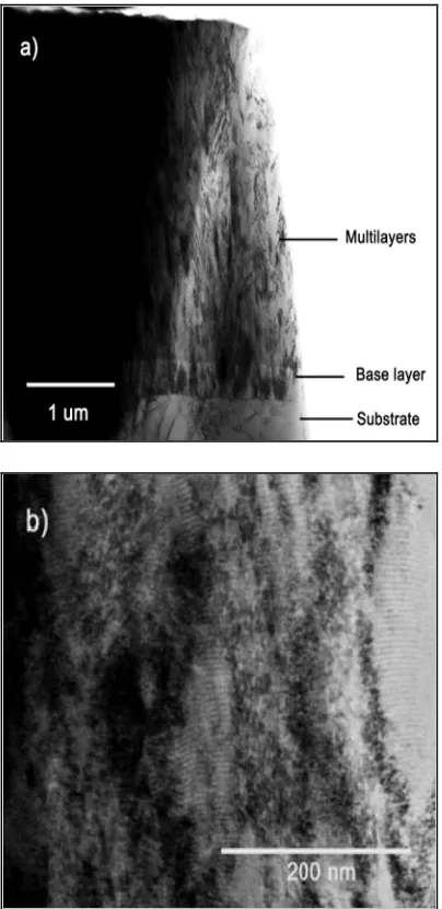
consistent with residual stress measurements. XRD measurements revealed that the coatings were under compressive stress of -4.72 GPa and -1.59 GPa for the H-H and UBM coatings respectively. Lower friction coefficient and sliding wear coefficients lower by a factor of two were measured for H-H coatings as compared to the UBM version. Enhanced hardness and sliding wear resistance in the HIPIMS deposited coatings has been attributed to the flat and sharp interfaces within the multilayer structure and a dense coating without inter-columnar voids obtained as a result of low energy ion bombardment during coating growth in HIPIMS discharge [12]. This improved structure can be seen in Figure 1(a) which is a low magnification image of a TEM cross-section of the CrN/NbN deposited by H-H. The 0.45 m CrN base layer grown on a clean and sharp interface is evident, which is a fingerprint of the HIPIMS pre-treatment [13]. The overall coating structure was found to be dense without inter-columnar voids and with very flat column tops resulting in low surface roughness. Further evidence of the effect of high ion irradiation can be seen in figure 1(b) where the alternating CrN and NbN nanolayers are separated by flat and sharp interfaces and show low layer waviness.
3.3 Erosion-corrosion results:
bombarding ions from the HIPIMS plasma and hence this can explain the near consistent E-corr values obtained under constant particle bombardment.
UBM deposited substrate shows significantly higher corrosion current densities in the electrochemical potential range of -400 mV to + 600 mV. The superior performance of H-H coated substrates in above potential range is notable especially when the coating thicknesses were same. These results also suggest that the coating removal rate, and hence consequently also the corrosion rate, for the H-H coating was lower than the UBM coating. This enhanced tribo-corrosion resistance of H-H coating can be attributed to the superior microstructure (inter-columnar void free) in the above potential range. In the potential range of -300 mV to + 350 mV both the coated substrates show passive behaviour even under particle bombardment suggesting an immediate reformation/ repair of the protective passive layer consisting of oxides and oxynitrides [15] of Chromium and Niobium. For the H-H coated substrates the protective nature of coating/ passive layer is more evident, limiting the current densities to near constant values. Erosion-corrosion is a complex phenomenon with a number of parameters affecting the combined wastage rates [16]. Factors such as particle type, size, shape, velocity, concentration in slurry, impact angle along with the chemical composition of the solution and electrochemical potentials have shown a marked effect on the total wastage rates and mechanisms of material removal [17]. Studies in the past have shown a synergistic effect between erosion and corrosion where corrosion assists mechanical wear in material removal [1,18].
microstructure and hence enhanced corrosion and erosion-corrosion resistance of the coating in these conditions as compared to that obtained from the UBM coating.
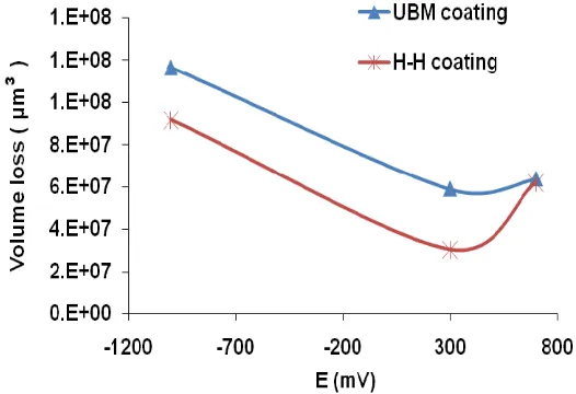
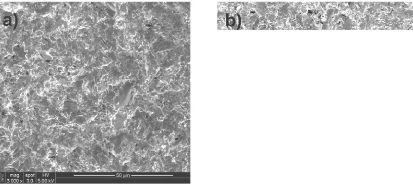
Consistent with the previous studies [3,11] volume loss for the passivating potentials of +300 mV for both coatings was lower than at cathodic potentials of -1000 mV where no corrosion of specimen is expected. The results obtained suggest an antagonistic (negative synergism) effect between erosion and corrosion [18]. The lower mass loss at +300 mV can be attributed to the protective nature of the passive layers of chromium (Cr) and niobium (Nb) formed in the electrochemical potential range of -300 mV and +350 mV [19]. Transport of the reacting species and corrosion reaction rates in the flowing fluid are higher [20]which can lead to the rapid reformation / repair of any passive layer being removed providing a cushioning effect to the incoming particles there by reducing the total mass loss. These results are consistent with the other studies where researchers have found that passive layer removal under solids-free impingement [20,21] and for conditions with suspended particles [22] depends on a critical value of velocity. Scanning electron microscopy images, figure 4 (a-b) revealed that at the end of the experimentation, both the coatings were completely removed rendering the bare substrates with platelet type deformation as observed for erosion, and erosion-corrosion of "ductile" materials [14,23].
thereby limiting the total volume loss [19]. EDX analysis of both the coatings exhibited that Cr concentration in the H-H coating (atomic weight 36%) was higher than the UBM (atomic weight 32%) coating suggesting that the higher synergy in the H-H coating at +700 mV can be attributed to the Chromium rich stochiometry of the coating which undergoes dissolution under erosion-corrosion conditions at such high potentials. It is estimated that this limited synergistic relation between erosion-corrosion for the H-H coating can be reduced by increasing the niobium content in the coating thereby improving its corrosion resistance, hardness and consequently erosion-corrosion resistance of the coating.
3.4: Erosion and corrosion contributions:
The total erosion-corrosion volume loss results obtained from the experiments can be further separated into individual contributions of erosion and corrosion [17],
KEC = KE + KC (i), which further can be divided as:
KE = Keo + Ke (ii)
KC = Kco + Kc (iii)
where:
KEC = Total volume loss due to erosion-corrosion
KE = Volume loss due to erosion
Keo = Volume loss in the absence of corrosion
Ke = Change in erosion contribution due to corrosion
KC = Volume loss due to corrosion
Kco =Volume loss in the absence of erosion (calculated by Faraday's Law).
Table 2 gives the individual contributions of erosion and corrosion for the coated substrates by HIPIMS and UBM coating technologies. As observed, at potentials + 300 mV and + 700 mV, the antagonistic effect of corrosion on erosion is clearly evident (negative Ke values) where the
passive layers lead to the reduced erosive wear of the coating. This effect is more evident in the HIPIMS deposited coating suggesting superior coating microstructure than the UBM deposited coating. At potentials of + 700 mV, this antagonistic effect appears reduced due to the dissolution of Chromium from the coating, a problem which can be addressed by increasing the niobium content of the coating in the future depositions.
4. Conclusions:
Nanoscale CrN/NbN multilayer were successfully deposited by HIPIMS and UBM technologies. Various micro-structural characterisation and erosion-corrosion experiments indicated:
1. HIPIMS deposited (H-H coating) coatings exhibited enhanced wear, erosion, corrosion and hence erosion-corrosion resistance compared with the UBM deposited coatings in these conditions. Volume loss analysis at different corroding conditions, namely (cathodic-1000 mV) and passivating (+300 mV) showed that HIPIMS (H-H) coating outperformed the UBM coating, except at +700 mV (anodic) where the volume loss was approximately similar.
3. Passivating behaviour (+300 mV) of the nanoscale CrN/NbN multilayer coating led to negative synergism (antagonistic effect) between erosion and corrosion. Passivating conditions resulted in lower volume losses than in erosion only conditions.
References
[1] R.J.K. Wood, Wear 261 (9) (2006) 1012.
[2] P.E. Hovsepian, D.B. Lewis, W.-. Münz, Surface and Coatings Technology 133-134 (2000) 166.
[3] M.M. Stack, Y. Purandare, P. Hovsepian, Surface and Coatings Technology, 188-189 (2004) 556.
[4] Y. Purandare, M.M. Stack, P. Hovsepian, Wear, 259 (1-6) (2005) 256.
[5] A.P. Ehiasarian, W.-. Münz, L. Hultman, U. Helmersson, I. Petrov, Surface and Coatings Technology 163-164 (2003) 267.
[6] C. Reinhard, A.P. Ehiasarian, P.E. Hovsepian, Thin Solid Films 515 (7-8) (2007) 3685. [7] Y. P. Purandare, A. P. Ehiasarian and P. Eh. Hovsepian, J. Vac. Sci. Technol. 26 (2) (2008) 288.
[8] Arutiun P. Ehiasarian, P. E. Hovsepian, W.-D. Munz, USA patent, US 10718435, (2005). [9] Arutiun P. Ehiasarian, Yolanda Aranda Gonzalvo, Terry D. Whitmore, Plasma Processes and Polymers 4 (S1) (2007) 309.
[10] J.B. Zu, I.M. Hutchings, G.T. Burstein, Wear 140 (2) (1990) 331.
[11] Y.P. Purandare, M.M. Stack, P.E. Hovsepian, Surface and Coatings Technology, 201 (1-2) (2006) 361.
[12] Papken Eh. Hovsepian , Arutiun P. Ehiasarian , Yashodhan P. Purandare, Reinhold Braun, Ian M. Ross, Plasma Processes and Polymers, DOI- ppap.200930412 (In Press).
[13] A. P. Ehiasarian, J. G. Wen, I. Petrov, J. Apply. Phys. 101 (2007) 054301.
[15] L. Thair, U. Kamachi Mudali, S. Rajagopalan, R. Asokamani, B. Raj, Corrosion Science 45 (9) (2003) 1951.
[16] M.M. Stack, S. Lekatos, F.H. Stott, Tribology International 28 (7) (1995) 445. [17] M.M. Stack, S. Zhou, R.C. Newman, Wear 186-187 (Part 2) (1995) 523. [18] M.M. Stack and N. Pungwiwat, Wear 256 (5) (2004) 565.
[19] Marcel Pourbaix, Atlas of Electrochemical Equilibria in Aqueous Solutions, NACE, [20] B. Poulson, Wear 233-235 (1999) 497.
[21] A. Neville and T. Hodgkiess, Wear 233-235 (1999) 596.
[22] M.M. Stack, N. Corlett, S. Turgoose, Wear 255 (1-6) (2003) 225. [23] A.V. Levy, Wear 108 (1) (1986) 1.
List of figure captions
Figure 1: TEM micrograph in bright field mode (a) low magnification cross-sectional view of the H-H coating showing base layer and through thickness coating (b) Nanoscale multilayer structure within the coating.
Figure 2: Current density curves obtained by polarising the specimens from -1000 mV to +1000 mV at a sweep rate of 1 mVs-1.
Figure 3: Volume loss observed for nanoscale CrN/NbN multilayer coated substrates at different electrochemical potentials.
Figure 2: Current density curves obtained by polarising the specimens from -1000 mV to +1000 mV at a sweep rate of 1 mVs-1.
[image:16.612.187.450.355.535.2]
Figure 4: SEM micrographs of the erosion-corrosion scars (a) +300 mV H-H coated substrate (b) +300 mV UBM coated substrate.
Coating type Bi-layer thickness (nm) Residual Stress (GPa) Micro hardness
[HK0.25N]
E [GPa]
Roughness (Ra)
Friction coeff.
(µ)
Sliding wear [m3N-1m-1]
Nano hardness
[GPa]
H-H 4.51 - 4.72 3393 381±35 0.07 m 0.46 1.22 x 10⁻¹⁵ 34 ± 4.2
[image:17.612.114.532.55.243.2]UBM 2.38 - 1.59 3001 382±59 0.04 µm 0.90 4.06 x 10⁻¹⁵ 31± 6.6
Table 1: Characterisation results obtained from various analytical experiments on the coatings. Coating Technology Corr. Potential (mV)
KEC KE KC Keo Ke
HIPIMS-HIPIMS
-1000 - 9.17 x 10⁷ - 9.17 x 10⁷ -
300 3.04 x 10⁷ 2.99 x 10⁷ 4.47 x 10⁵ 9.17 x 10⁷ -6.18 x 10⁷
700 6.20 x 10⁷ 8.33 x 10⁶ 5.37 x 10⁷ 9.17 x 10⁷ -8.34 x 10⁷
HIPIMS-UBM
-1000 - 1.16 x 10⁸ - 1.16 x 10⁸ -
300 5.89 x 10⁷ 5.00 x 10⁷ 8.87 x 10⁶ 1.16 x 10⁸ -6.64 x 10⁷
700 6.36 x 10⁷ 1.84 x 10⁷ 4.52 x 10⁷ 1.16 x 10⁸ -9.80 x 10⁷
[image:17.612.90.547.338.423.2]