Rochester Institute of Technology
RIT Scholar Works
Theses Thesis/Dissertation Collections
2011
Versatile FPGA architecture for skein hashing
algorithm
David Webster
Follow this and additional works at:http://scholarworks.rit.edu/theses
This Thesis is brought to you for free and open access by the Thesis/Dissertation Collections at RIT Scholar Works. It has been accepted for inclusion in Theses by an authorized administrator of RIT Scholar Works. For more information, please [email protected].
Recommended Citation
Versatile FPGA Architecture for Skein Hashing Algorithm
by
David M. Webster
A Thesis Submitted in Partial Fulfillment of the Requirements for the Degree of Master of Science in Computer Engineering
Supervised by
Prof. Marcin Łukowiak
Department of Computer Engineering Kate Gleason College of Engineering
Rochester Institute of Technology Rochester, New York
Approved By:
Prof. Marcin Łukowiak
Department of Computer Engineering
Prof. Stanisław Radziszowski Department of Computer Science
Prof. Roy Melton
Department of Computer Engineering
Prof. Alan Kaminsky
Thesis Release Permission Form
Rochester Institute of Technology
Kate Gleason College of Engineering
Title: Versatile FPGA Architecture for Skein Hashing Algorithm
I, David M. Webster, hereby grant permission to the Wallace Memorial Library to
re-produce my thesis in whole or part.
David M. Webster
Dedication
To family and to my fianc´e
Acknowledgments
Thank you to all of my thesis advisers for their help through this research. Their time and
effort is greatly appreciated. Thanks especially to Dr. Lukowiak for bringing this research
Abstract
Digital communications and data storage are expanding at fast rates, increasing the need
for advanced cryptographic standards to validate and provide privacy for that data. One
of the basic components commonly used in information security systems is cryptographic
hashing. Cryptographic hashing involves the compression of an arbitrary block of data into
a fixed-size string of bits known as the hash value. These functions are designed such that
it is computationally infeasible to determine a message that results in a given hash value.
It should also be infeasible to find two messages with the same hash value and to change
a message without its hash value being changed. Some of the most common uses of these
algorithms are digital signatures, message authentication codes, file identification, and data
integrity.
Due to developments in attacks on the Secure Hash Standard (SHS), which includes
SHA-1 and SHA-2 (SHA-224, SHA-256, SHA-384, SHA-512), the National Institute of
Standards and Technology (NIST) will be selecting a new hashing algorithm to replace
the current standards. In 2008, 64 algorithms were entered into the NIST competition and
in December 2010, five finalists were chosen. The final candidates are BLAKE, Keccak,
Grøstl, JH, and Skein. In 2012, one of these algorithms will be selected for the Secure Hash
Algorithm 3 (SHA-3).
This thesis focuses on the development of a versatile hardware architecture for Skein
that provides both sequential and tree hashing functions of Skein. The performance
hashing of multiple unique messages and reduced area tree hashing implementations.
Ad-ditional result of this thesis is a comprehensive overview of the newly developed
architec-tures and an analysis of their performance in comparison with other software and hardware
Contents
Dedication. . . iii
Acknowledgments . . . iv
Abstract . . . v
1 Introduction. . . 1
1.1 Motivation . . . 1
1.2 Skein . . . 2
2 Skein Specification . . . 3
2.1 Threefish . . . 6
2.1.1 MIX and Permute . . . 7
2.1.2 Subkey Generation . . . 8
2.2 Unique Block Iteration . . . 12
2.2.1 Configuration UBI . . . 13
2.2.2 Message UBI . . . 14
2.2.3 Output UBI . . . 15
2.2.4 Tree Hashing . . . 17
3 Supporting Work . . . 20
3.1 Iterative . . . 20
3.2 Unrolled . . . 22
3.4 Duplicate Cores . . . 27
3.4.1 Subkey Generation . . . 29
4 Design Methodology . . . 32
4.1 Versatile Unrolled and Pipelined Architecture . . . 32
4.1.1 Threefish Architecture . . . 33
4.1.2 Deep Pipelined Architecture . . . 37
4.1.3 Subkey Generator . . . 38
4.1.4 Tree Hashing with Pipelined Core . . . 41
4.1.5 Control . . . 45
5 Testing Methodology . . . 49
5.1 VHDL Simulation . . . 49
5.2 Hardware Verification . . . 52
5.3 Synthesis and Implementation Automation . . . 55
6 Performance Results & Analysis . . . 59
6.1 Sequential Hashing . . . 60
6.2 Multiple Message Hashing . . . 61
6.3 Pipelined Tree Hashing Performance . . . 64
6.3.1 Message Processing Overhead . . . 65
6.3.2 Tree Performance . . . 70
7 Conclusions . . . 82
List of Figures
2.1 Threefish block cipher diagram . . . 3
2.2 Tweak parameters diagram [14] . . . 4
2.3 Threefish block in MMO configuration . . . 5
2.4 First four rounds of Threefish-256 [14] . . . 8
2.5 MIX operation . . . 9
2.6 Generation of the first two subkeys forNW = 4 . . . 11
2.7 UBIs for simple Skein hashing [14] . . . 12
2.8 Message UBI forM with3·Nb bytes . . . 15
2.9 Skein with different size outputs . . . 16
2.10 Example of Skein hash tree [14] . . . 17
2.11 Tree structures with differentYLandYF [1] . . . 19
3.1 Iterative Threefish architecture [11] . . . 21
3.2 Eight-round unrolled Threefish architecture [17] . . . 23
3.3 Dual subkey generator [17] . . . 24
3.4 Pipelined architecture [9] . . . 26
3.5 Pipelined architecture with 4 (left) and 8 (right) pipeline registers . . . 28
3.6 MuxSwitch subkey generator [11] . . . 30
3.7 Shift register key generator [17] . . . 31
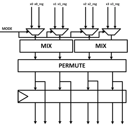
4.1 Versatile Threefish round architecture . . . 34
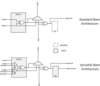
4.2 Multiplexed 64-bit adder using single 6-2 LUT . . . 35
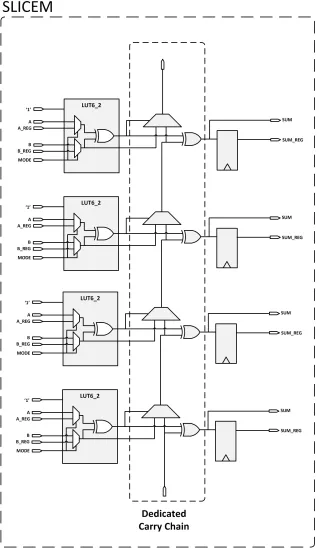
4.3 Four-bit adder in single Xilinx SLICEM . . . 36
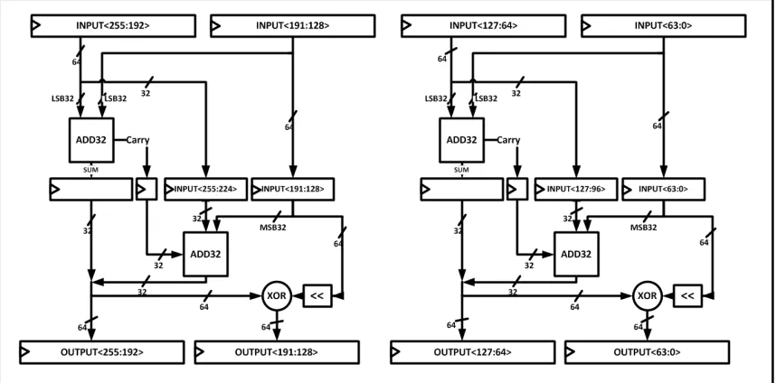
4.4 Deep pipeline MIX architecture . . . 37
4.5 Subkey generator . . . 40
4.6 Pipelined tree hashing,YL= 1,YF = 1, msgBlocks = 16 . . . 42
4.7 Pipelined tree hashing,YL= 2,YF = 2, msgBlocks = 16 . . . 43
4.8 YL= 1,YF = 4, msgBlocks = 16 . . . 44
4.9 YL= 4,YF = 4, msgBlocks = 4096 . . . 45
4.11 Block diagram of complete Skein core . . . 48
5.1 Message storage format . . . 51
5.2 Hardware testing framework . . . 53
5.3 Hardware testing flow . . . 54
5.4 ATHENa results for SHA-3 candidates [8] . . . 56
6.1 Tree structure with differentYLandYF [1] . . . 66
6.2 Message overhead forYF =YL, msgBlocks= 8192 . . . 67
6.3 Skein with different size outputs . . . 68
6.4 Message overhead for tree hashing . . . 69
6.5 YL= 4,YF = 4, msgBlocks = 4096 . . . 73
6.6 Maximum theoretical speedup of pipelined tree hashing . . . 74
6.7 Maximum theoretical speedup of pipelined tree hashingYF =YL . . . 75
6.8 Maximum theoretical speedup of pipelined tree hashingYF =YL . . . 76
6.9 Maximum theoretical efficiency of pipelined tree hashing . . . 77
6.10 Maximum theoretical efficiency of pipelined tree hashingYF =YL . . . 78
6.11 Theoretical execution time . . . 80
List of Tables
2.1 Tweak parameters [14] . . . 4
2.2 Skein type field values . . . 5
2.3 Skein symbol definitions . . . 6
2.4 Threefish variable definitions . . . 7
2.5 MIX rotation values [14] . . . 9
2.6 Permutation values [14] . . . 10
2.7 Skein configuration string [14] . . . 13
2.8 Skein tree hashing symbol definitions . . . 17
3.1 Iterative architecture results . . . 21
3.2 Four round unrolled results . . . 22
3.3 8-round unrolled results . . . 25
3.4 Skein-512 ASIC results (32nm Technology) [9] . . . 27
3.5 Skein-512 pipelined hardware results . . . 27
3.6 Multiple core results [16] . . . 29
3.7 Subkey hardware for Skein-512 [1] . . . 30
4.1 Subkey generator signals for Skein-256 . . . 39
4.2 Skein core inputs/output . . . 47
5.1 Skein-256 - Device : Virtex-5 XC5VLX110-3 . . . 57
5.2 Skein-256 - Device : Virtex-6 XC6VLX240T-1 . . . 57
5.3 Skein-256 - Device : Virtex-6 XC6VLX240T-3 . . . 57
6.1 Variables for evaluating Skein hardware performance . . . 59
6.2 Skein 256 Eight-round unrolled results . . . 63
6.3 Calculating the UBI nodes in a Skein tree [1] . . . 67
6.4 Calculation ofLATL . . . 71
6.5 Calculation ofLATF . . . 72
Chapter 1
Introduction
One of responsibilities of The National Institute of Standards and Technology (NIST) is to
determine standards for securing and maintaining the integrity of digital data. In particular
the Computer Security Division (CSD) of NIST defines a set of secure hashing algorithms
(SHA) in order to accomplish these goals. In 2005 a differential attack on SHA-1 was
announced by Prof. Xiaoyun Wang that would discover a hash collisions with complexity
263rather than the ideal280operations [4]. More recent research has determined differential
paths with complexity 252[3]. With this new discovery in addition to collisions on MD4,
MD5, SHA-0, and collision attacks on SHA-1, NIST initiated a competition to develop a
new hashing algorithm to be named SHA-3 [15]. Since the initial submissions, the field
of candidates has been narrowed to five finalists: Keccak, Grøstl, JH, BLAKE, and Skein.
Each of these algorithms has been carefully scrutinized by the cryptographic community
and NIST for security. The performance of these algorithms with respect to throughput
and area on different platforms will also be a factor when selecting the new algorithm for
SHA-3.
1.1
Motivation
In attempts to achieve higher performance, FPGAs have been utilized as one of the
to provide a tree hashing mode, this work has chosen to focus on developing a novel
archi-tecture for Skein. There are currently a few different FPGA archiarchi-tectures for Skein, each
with its own performance advantages. This flexibility in implementation options makes
Skein a suitable choice for hardware development. In addition to being secure Skein’s uses
basic operations of addition and exclusive OR. These simple operations make FPGAs an
ideal target platform. Multiple FPGA architectures have been developed for Skein, and this
work intends to contribute to Skein hardware development by developing a more versatile
architecture. A detailed evaluation of the performance of this architecture will be provided
to aid other researchers in evaluating this design and other future designs.
1.2
Skein
Although the security of Skein is not a focus of this work, its security makes it a strong
competitor for SHA-3. NIST’s report on the second round candidates stated that the most
severe attacks on Skein include a key-recovery attack on 39 rounds of Threefish-256 and
42 rounds of Threefish-512 as well as a rotational distinguisher on 53 and 57 rounds of the
Skein-256 and Skein-512 compression fucntions, respectively [13]. Skein is also one of the
most flexible SHA-3 candidates. With its multiple internal state sizes and any size out, it
can be used as a direct substitution for any of the current SHA hash functions [14] as well
Chapter 2
Skein Specification
Skein was developed by a team led by Bruce Schneier and Niels Ferguson and was selected
as a finalist for the NIST SHA-3 competition [13]. The base component of Skein is the
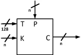
Threefish tweakable block cipher. The Threefish cipher has three inputs, the plaintext, key,
and tweak as shown in Figure 2.1. Using this block cipher allows Skein to operate in a
[image:15.612.244.384.416.510.2]variety of different configurations as well as improve the security of the hashing function.
Figure 2.1: Threefish block cipher diagram
The Threefish function can be represented as T F(K, P, T), with T being the current
tweak value, P the current plaintext input, and K the key input. The Skein family of
hash functions can use multiple internal state sizes as well as multiple output sizes. The
internal state sizes are based off of the internal state size of Threefish. The three standard
state sizes for Threefish are 256, 512, and 1024 bits. The output size can be of any length
and is independent of the state size. The accepted naming convention is
output of 256-bits is referred to as Skein-256-256. Since the output size is independent of
the internal state size, the variants are designated as Skein-256, Skein-512, and Skein-1024
to represent the internal state size only.
The tweak input to Threefish contains multiple parameters that vary depending on the
configuration and message. Figure 2.2 illustrates the tweak value with more detailed
[image:16.612.117.507.287.549.2]de-scriptions in Table 2.1.
Figure 2.2: Tweak parameters diagram [14]
Table 2.1: Tweak parameters [14]
Name Bits Description
Position 0– 95 The number of bytes in the string processed so far (including this block)
reserved 96–111 Reserved for future use, must be zero
TreeLevel 112–118 Level in the hash tree, zero for non-tree computa-tions.
BitPad 119 Set if this block contains the last byte of an input whose length was not an integral number of bytes. 0 otherwise.
Type 120–125 Type of the field (config, message, output, etc.) First 126 Set for the first block of a UBI compression. Final 127 Set for the last block of a UBI compression.
The Threefish block cipher is used in a Matayas-Meyer-Oseas (MMO) construction as
shown in Figure 2.3 [7]. The output of the MMO (Hi) is equal to exclusive OR of the
message block and the output of the Threefish block, which will be described in the Skein
Specification section.
Figure 2.3: Threefish block in MMO configuration
Each UBI is responsible for processing one of the arguments in Table 2.2, each of which
serves a different function. When using multiple arguments, the arguments are processed
in increasing order by value.
Table 2.2: Skein type field values
Symbol Value Range Description
Tkey 0 Key (for MAC and KDF)
Tcf g 4 Configuration block
Tpcs 8 Personalization String
TP K 12 Public key(for digital signature hashing)
Tkdf 16 Key identifier (for KDF)
Tnon 20 Nonce (for stream cipher or randomized hashing)
Tmsg 48 Message
Tout 63 Output
Considering the different sizes and configurations of Skein, several variables are defined
to aid in detailing the algorithm. These variables with their range of values and descriptions
are shown in Table 2.3. Many of these variables are explained in more detail in following
Table 2.3: Skein symbol definitions
Symbol Value Range Description
Nb 32, 64, 128 Internal state size in bytes. No 1 - (264−1) Output size in bits
NM 1 - (296−1) Message size in bytes YL 1 - (28−1) Tree leaf size encoding YF 1 - (28−1) Tree fan-out encoding YM 1 - (28−1) Maximum tree height
M 0 - (299−1) Message of maximum length296−1bytes G 0 - (28−1) Chaining variable from previous UBI ofN
b bytes. Ts See Table 2.1 128-bit initial tweak value
2.1
Threefish
Threefish is the tweakable block cipher used inside each UBI. This block cipher takes three
inputs: the key (K) ofNb bytes, the plaintext message input (P) ofNbbytes, and the tweak
(T) of 128-bits. Threefish operates internally on 64-bit words, and thus all of the inputs
are split into multiple 64-bit words. Each variant of Skein corresponds to the equivalent
variant of Threefish (Skein-256 uses Threefish-256, each withNb= 32). The output (C) of
Threefish is also a Nb-byte value. The basic representation of the Threefish block cipher
was shown in Figure 2.1. From the various inputs, multiple variables can be defined for
Threefish. These variables are described in Table 2.4.
Within the Threefish block cipher are three primary operations: MIX, permute, and
subkey addition. Each of these operations is described in detail in following sections. A set
ofNw/2 MIX operations and a single Permute function constitutes a single Threefish round.
For Skein-256 and Skein-512, the total number of rounds (Nr) is 72, and 80 for
Skein-1024. Before the first round and after every fourth subsequent round, a subkey addition is
Table 2.4: Threefish variable definitions
Variable Definition
Nw number of 64-bit words in each message/key block (8·Nb/64) Nr number of rounds in the block cipher
i word index (0, . . . , Nw−1) j word index (0, . . . , Nw/2−1) d current round (0, . . . , Nr−1) k0, . . . , kNw−1 64-bit words of key input
t0, t1 64-bit words of tweak input
p0, . . . , pNw−1 64-bit words of plaintext input
vd,i ith word of state after d rounds s subkey number
pi 64-bit block of plaintext or message block input ci 64-bit block of ciphertext or output block input
2.1.1
MIX and Permute
Each Threefish round contains a number of MIX operations and a single permute operation.
The MIX operation is comprised of an unsigned 64-bit addition, a rotation (logical shift),
and an exclusive OR. Given two input words (x0,x1), the MIX operation produces outputs
(y0,y1) according to the following equations.
y0 := (x0+x1) mod 264
y1 := (x1≪R(dmod 8),j)⊕y0
A diagram of the MIX function can be seen in Figure 2.5, and Table 2.5 shows the rotation
values for all variants of Skein. The rotation value is dependent upon the word indexj and
round number mod 8 (d mod8). Since two words are processed by each MIX block,Nw/2
MIX blocks are required for each of the Skein variants. For Skein-256, Skein-515, and
Skein-1024,Nw is 4, 8, and 16 respectively, thus requiring 2, 4, and 8 MIX blocks.
After the MIX operation, the 64-bit outputs are reordered before entering the next
Figure 2.4: First four rounds of Threefish-256 [14]
permutations are achieved simply by routing the outputs of one round to the corresponding
inputs of the next round.
2.1.2
Subkey Generation
Before the first MIX and permute and after every fourth subsequent MIX and permute
operation, a subkey is added to the current Threefish state. The Nr/4 + 1 subkeys are
generated using the output of the previous Threefish block (the key), the tweak, and the
subkey number. Both the key (K) and tweak (T) are extended by a single word using
the formulas shown below. C240 is a constant defined as 0x1BD11BDAA9FC1A22. This
Figure 2.5: MIX operation
Table 2.5: MIX rotation values [14]
Nw 4 8 16
j 0 1 0 1 2 3 0 1 2 3 4 5 6 7
0 14 16 46 36 19 37 24 13 8 47 8 17 22 37
1 52 57 33 27 14 42 38 19 10 55 49 18 23 52
2 23 40 17 49 36 39 33 4 51 13 34 41 59 17
d= 3 5 37 44 9 54 56 5 20 48 41 47 28 16 25
4 25 33 39 30 34 24 41 9 37 31 12 47 44 30
5 46 12 13 50 10 17 16 34 56 51 4 53 42 41
6 58 22 25 29 39 43 31 44 47 46 19 42 44 25
7 32 32 8 35 56 22 9 48 35 52 23 31 37 20
how this value was determined can be found in the Skein specification [14].
kNw :=C240⊕
Nw−1
M
i=0
ki
Table 2.6: Permutation values [14]
i=
0 1 2 3 4 5 6 7 8 9 10 11 12 13 14 15
4 0 3 2 1
Nw = 8 2 1 4 7 6 5 0 3
16 0 9 2 13 6 11 4 15 10 7 12 3 14 5 8 1
Using the extended key and tweak, each subkey sks is generated according to the
expres-sions below.
sks,i :=k(s+i) mod (Nw+1) fori= 0, . . . , Nw−4
sks,i :=k(s+i) mod (Nw+1)+tsmod 3 fori=Nw−3
sks,i :=k(s+i) mod (Nw+1)+t(s+1) mod 3 fori=Nw−2
sks,i :=k(s+i) mod (Nw+1)+s fori=Nw−1
This subkey generation can be more easily understood through the illustration in Figure
2.6. This figure shows that after each subkey is generated, the extended key and tweak
are shifted one word to the left, and the additions are performed as before. There are two
standard approaches to implementing the subkey generator in hardware, both of which are
2.2
Unique Block Iteration
Unique Block Iteration is the chaining of multiple Threefish blocks together in order to
compress an arbitrary length input to a fixed size output. Skein uses UBIs to execute the
processing for each of the arguments of Skein shown in Table 2.2. Each UBI has three
inputs and a single output. The inputs to a UBI are the message (M) of arbitrary length
with a maximum length of (296 −1) bytes, an initial chaining variable (G0) ofNb bytes,
and an initial tweak value of 128-bits (Ts). The output of any UBI is also of size Nb
bytes. The UBI for each of these arguments contains a different number of Threefish blocks
depending on the size of the message input. A UBI can be represented by the expression
shown in Equation 2.1. This work focuses on simple Skein hashing, which utilizes only
the Configuration, Message, and Output UBIs as shown in Figure 2.7. The remaining UBI
types are detailed in the Skein specification [14].
Gi =U BI(Gi−1, M, Ts) (2.1)
Within a UBI, multiple Threefish blocks may be chained together. When multiple
blocks are chained together, the fields in the tweak are varied to customize the
particu-lar block ofM being processed.
2.2.1
Configuration UBI
The configuration UBI is the first UBI to be processed for a simple Skein hash and is
re-quired for all methods of Skein hashing. The message input to this UBI is a configuration
string ofNb bytes. The configuration string contains multiple parameters, which are shown
in Table 2.7. Several parameters are variable and define the form of hashing being
per-formed. The remaining parameters are currently fixed values, which include the schema
identified, which is simply the ASCII string “SHA3”, the version number, which is
cur-rently 1, and multiple reserved reserved bytes set to 0. The variable parameters include
No indicating the output length being used, and the tree configuration parameters (YL,YF,
YM), which determine the leaf size, fanout, and maximum height of the constructed tree.
The tree mode parameters are explained in more detail in the Tree Hashing section.
Table 2.7: Skein configuration string [14]
Size in
Offset Bytes Name Description
0 4 Schema identifier The ASCII string “SHA3” = (0x53, 0x48, 0x41, 0x33)
4 2 Version number Currently set to 1
6 2 Reserved, set to 0
8 8 Output length No
16 1 Tree leaf size enc. YL
17 1 Tree fan-out enc. YF
18 1 Max. tree height YM
19 13 Reserved, set to 0
Using the configuration string, one can define the UBI using the following inputs and
the output defined in Equation 2.2.
G:=K0, Output of Key UBI or string ofNbzero bytes
M :=C, Configuration string as defined in Table 2.7
G0 =U BI(K0, C, Tcf g2120) (2.2)
2.2.2
Message UBI
After the configuration UBI, the message to be hashed is processed. In the message UBI
multiple Threefish blocks are used in order to process the entireNM bytes of the message.
Since an entire block ofNbbytes is required for the plaintext input of each Threefish block,
a message that is not an integer multiple of 8 bits must be padded by setting the most
sig-nificant unused bit to “1” and the remaining unused bits to “0” until a multiple ofNb bytes
is achieved. The padded message is split intodNM/Nbemessage blocks (M0, . . . , Mk−1),
and therefore equally as many Threefish blocks are chained together to complete the
mes-sage UBI. For sequential Skein hashing the mesmes-sage UBI is processed using the following
inputs and output defined in Equation 2.3.
G:=G0, Output of Configuration UBI
M :=M, Message to be hashed of lengthNM bytes
TS :=Tmsg, Initial tweak value.
G=U BI(G0, M, Tmsg2120) (2.3)
Figure 2.8 shows an example of a message UBI for a message with exactly3·Nbbytes. The
chaining variable G0 is the output from the configuration UBI. The message input is the
first block (M0) of the message, and the initial tweakT0 has the first block field set to “1”
and the position is set toNb. The key input to the next two Threefish blocks is the output
of the previous Threefish block. ForT1, the first block field is reset to “0” and the position
is set to2·Nb. The last tweakT2 sets the last block field to “1” and the position to3·Nb.
H2would become the chaining variable input for the output UBI. For a message that is not
an integer multiple ofNb bytes before padding, the position field of the last tweak is set to
Figure 2.8: Message UBI forM with3·Nb bytes
2.2.3
Output UBI
The final stage of processing is the Output UBI. This stage takes the chaining variable from
the Message UBI and generates theNobits for the final hash value. IfNois equal to or less
than that of 8*Nb, only one output UBI is required to generate the final output of Skein.
IfNo is greater than 8*Nb, dNo/(8∗Nb)eUBIs are needed to compute the final output of
Skein. The inputs to the Output UBI are defined as follows :
G:=G, Output of Message UBI
M := 0,1,2, . . ., Byte value corresponding to which Output UBI is being processed
TS :=Tout, Initial tweak value.
The final hash output is the firstNobits ofH as defined in Equation 2.4 are used.
H =U BI(G,0, Tout2120)||U BI(G,1, Tout2120)||U BI(G,2, Tout2120)|| · · · (2.4)
Examples of Skein with different output sizes are illustrated in Figures 2.9(a) and 2.9(b).
Figure 2.9(a) shows how the UBIs of Skein are chained together in the case ofNo≤8·Nb,
and thus three Output UBIs are required as illustrated in Figure 2.9(b).
(a) No≤8·Nb (b) 2·Nb·8≤No≤3·Nb·8
2.2.4
Tree Hashing
In sequential Skein, the message is processed in a single UBI. In order to allow for the
ability to speed up the message processing, the designers of Skein included a tree hashing
option. In tree hashing, the message UBI can be split up into multiple UBIs to construct a
tree. A diagram depicting a generic hash tree in shown in Figure 2.10.
Table 2.8: Skein tree hashing symbol definitions
Symbol Description
YL The leaf size encoding. Number of blocks processed by each leaf node is2YL,YL≥1 YF The fan-out encoding. The fan-out of a tree is2YF withYF ≥1
YM The maximum tree height;YM ≥2, 255 if not specified Nl Leaf size,Nb2YL
Nn Node size,Nb2YF
The structure of the tree is defined byYL, YF, and YM. These parameters are defined
along with other important variables for tree hashing as shown in Table 2.8.
Figure 2.10: Example of Skein hash tree [14]
stage of processing, usually the Tcf g stage. Equations 2.5, 2.6, and 2.7, describe the tree
processing of a message (M). The message is initially split into k = dNM/(Nb ·2YL)e
message blocks (M0,0, . . . , M0,k−1) of sizeNb·8·2YL bytes forM0,0 throughM0,k−2 and
less than or equal toNb ·8·2YL bytes for M0,k−1. The outputs of the leaf level UBIs are
concatenated to produce a new messageM1 (Eq. 2.5). This new message is then split into
j blocks of sizeNb·2YF. Each subsequent level is processed (Eq. 2.6) until the root node
is reached . The root node produces the chaining variable to the output UBI (G0) using
Equation 2.7. The tweak for each of the following equations takes into consideration the
tree level, and the position field now indicates how many bytes have been procesed by the
UBIs at the current level.
M1 =kki=0−1 U BI(G, M0,i, T) (2.5)
Ml+1 =kji=0−1 U BI(G, Ml,i, T) (2.6)
Go =U BI(G, MYM−1, T) (2.7)
Varying the parametersYL, YF, and YM produces different tree structures for a given
message. Figure 2.11 illustrates different tree structures for a message of8·Nb bytes. In
each of the examplesYF andYLare varied. ForYL= 1, the leaf level will contain 4 UBIs as
each UBI will process2YL message blocks, and forY
L= 2 each leaf level UBI can process
4 message blocks. Each subsequent level processes2YF outputs from the previous level. If
a maximum tree height (YM) is defined, once the tree reaches this height, the root node will
process all UBI outputs of the previous level. IfYM is undefined, the default maximum tree
Chapter 3
Supporting Work
When designing FPGA architectures for Skein, there are many different factors to consider
such as maximum clock frequency, latency, area, and the resulting throughput. Early
de-signs focused on methods of improving the sequential Skein hashing but recent research has
developed more novel architectures. In [1], Aric Schorr developed a multicore architecture
in order to utilize Skein’s tree hashing mode, while in [9] Walker, Sheikh, Mathew, and
Kr-ishnamurthy developed an application specific integrated circuit (ASIC) capable of hashing
multiple unique messages simultaneously. This work furthers the above mentioned work to
develop flexible and high-performance architectures utilizing unrolled and pipelined
archi-tectures to perform sequential, multiple message, and tree hashing. This is accomplished
without any Configurable Logic Block (CLB) overhead in the primary Threefish
compres-sion function core.
3.1
Iterative
The first FPGA architecture developed for Skein by Men Long was described in [11]. The
main focus of his work was the iterative architecture, which is the most straightforward
design as only one round is implemented in hardware. This round contains the 64-bit
adders and exclusive ORs for the MIX function. The dynamic rotations of Threefish require
multiplexers to switch between the different possible rotations. A set of8·Nb registers is
state of Threefish after each round, the latency of the iterative architecture is 72 clock cycles
for Skein-256 and Skein-512, and 80 cycles for Skein-1024. At the input to the Skein
round hardware is a multiplexer that selects between the message input block or the current
Threefish state. The exclusive OR at the output of the round logic produces the chaining
value or hash output as required by the MMO construction. The last component of the
iterative hardware is the subkey generator. The core iterative architecture used to perform
Skein hashing is shown in Figure 3.1. Although the iterative architecture is not used in this
work, important design considerations regarding subkey generation can be gained from
the work of Long [11] and Schorr [1] in order to achieve the highest performance for the
architecture presented in this work.
Figure 3.1: Iterative Threefish architecture [11]
Table 3.1: Iterative architecture results
Design Device Bits Slices Clk Latency TP
(MHz) (Cycles) (Mbps)
[11] XC5VLX50-3 256 1001 114.9425 72 408.68
[11] XC5VLX50-3 512 1877 114.9425 72 817.37
3.2
Unrolled
Although the iterative approach is the most straightforward, the performance results are
not satisfactory. One of the bottlenecks is the multiplexers required to implement the
dy-namic rotations in the MIX operation. In order to eliminate the delay incurred through the
multiplexers, designers can unroll the hardware to reduce the size or completely eliminate
these multiplexers [17]. To determine how many times to unrolled the hardware, specific
elements of the Skein algorithm are examined. The first option is to unroll the hardware
4 times, since subkeys are added to the Threefish state every 4th round. This architecture
requires 4 full MIX and permute operations to be implemented in hardware, and the subkey
generator remains the same. Although multiplexers are still required to handle the dynamic
shifts, their size is greatly reduced from 8-1 multiplexers to 2-1 multiplexers. Unrolling 4
rounds increases the critical path and thus lowers the maximum achievable clock frequency,
but in turn decreases the latency to 18 clock cycles [11]. Long’s results along with the
re-sults of other 4-round unrolled architectures are shown in Table 3.2. Long’s throughput
is improved through the unrolling, but clearly the his subkey generation architecture still
hinders this design which is discussed in a later section.
Table 3.2: Four round unrolled results
Design Device Bits Slices Clk Latency TP
(MHz) (Mbps)
[11] XC5VLX50-3 512 2662 40.8 18 1161
[5] Virtex-5* 512 1716 119.1 19 3209
[10] XC5VLX30-3 256 854 115.0 21 1482
[2] Virtex-5* 512 1786 83.7 22 1945
* Unspecified Virtex-5 FPGA
Further improving upon the 4-round unrolled approach, Tillich’s 8-round unrolled
de-sign has been the inspiration for most of the recent unrolled dede-signs [17]. By unrolling
8 rounds, all dynamic shifts of the MIX operation are eliminated and these shifts are
additional hardware is required to implement the extra rounds; however the subkey
gener-ator must also be modified. Since a subkey must be added every 4th round, two subkeys
must be generated in each clock cycle. Additional hardware is required to generate both
subkeys each clock cycle. Tillich’s 8-round unrolled architecture and dual subkey generator
are shown in Figures 3.2 and 3.3 respectively.
Once again, the critical path is increased, and the latency is further decreased to 10
clock cycles. The performance of 8 round unrolled architectures has proven to the be the
most efficient solution for sequential hashing on FPGAs. Results for several different 8
round unrolled architectures are shown in Table 3.3.
Table 3.3: 8-round unrolled results
Design Device Bits Slices Clk Latency TP
(MHz) (Cycles) (Mbps)
[17] XC5VLX110-3 256 937 68.4 10 1751.0
[17] XC5VLX110-3 512 1632 69.0 10 3534.8
[17] XC5VLX110-3 1024 2994 68.9 11 6414.0
3.3
Pipelined
A pipeline Skein architecture was first introduced by Walker et al. in [9] shows benefits of
pipelining unrolled architectures through an Application Specific Integrated Circuit (ASIC)
design. When pipelining an unrolled Skein architecture, registers are inserted between each
round. In turn, the critical path is decreased thus increasing the achievable clock frequency.
However, due to data dependencies, hashing a single message with a pipelined design will
see a decrease in performance as a pipelined design increases latency. A pipelined design
allows for multiple unique messages to be hashed simultaneously. This type of architecture
would be especially beneficial in a system where multiple data stream must be processed
at the same time such a network router [9]. This establishes that a pipelined hardware
architecture can be efficiently utilized in certain applications. Figure 3.4 shows the high
level diagram of the pipelined architecture.
Although the most obvious application of a pipelined architecture is to hash multiple
messages simultaneously, it has been proposed in [11] and in [1], that tree hashing could
also benefit from a pipelined architecture. Since tree hashing splits a single message UBI
into multiple UBIs, it would be possible to execute multiple UBIs simultaneously using a
duplicate core model [1].
Figure 3.4: Pipelined architecture [9]
The results for the ASIC design are shown in Table 3.4, and although performance of
this circuit can not directly be compared to FPGA performance, the area overhead
percent-age and speedup for each of the pipelined architectures in [9] can give some insight as to
what to expect in a pipelined architecture on an FPGA. The design with only one pipeline
register is equivalent to an 8 round unrolled architecture. The 2, 4, and 8 pipeline
regis-tered architectures insert a register every fourth, every other, and every round respectively.
Simplified diagrams of the 4 and 8 pipeline registered architectures are show in Figure 3.5.
In [6] several different pipelined Skein FPGA implementations were developed for
Skein-512. These implementations include a 4-round unrolled architecture with two pipeline
ar-results for these designs is shown in Table 3.5
Table 3.4: Skein-512 ASIC results (32nm Technology) [9]
Pipeline Area Clk Latency Throughput Speedup Area
Registers (Gates) (MHz) (Cycles) (Gbps) Overhead
(%)
1 57,931 631.31 10 32.32 1.00 0.00
2 60,395 1126.13 20 57.66 1.78 4.25
4 62,954 1736.11 40 88.89 2.75 8.67
8 70,071 2380.95 80 121.90 3.77 20.96
Table 3.5: Skein-512 pipelined hardware results Design Architecture Slices Throughput
(Mbps)
4/2 [6] Virtex5 2314 5013
4/5 [6] Virtex5 3942 6141
8/10 [6] Virtex5 8831 10973
4/2 [6] Virtex6 1818 5649
4/5 [6] Virtex6 3209 7664
8/10[6] Virtex6 7323 11982
3.4
Duplicate Cores
An additional architecture for Skein is aimed at efficiently processing messages using Skein
tree hashing. This architecture, developed by Aric Shorr [1], uses multiple unrolled cores
to process multiple UBIs of the message stage of Skein simultaneously. Each core is
con-nected to a central controller which assigns each core a particular UBI to process. This
architecture was designed for scalability such that only non-bus signals are added when the
number of cores is increased. Performance results of this archtecture are shown in Table
3.6.
The handling of the message in memory was also carefully examined, and a
Table 3.6: Multiple core results [16]
Device Input block Slices Clk Latency Throughput Number
size (bits) (MHz) (Cycles) (Mbps) of cores
XC5VLX110-3 256 3024 59.3 10 3037 2
XC5VLX155-3 256 5657 54.9 10 5625 4
XC5VLX155-3 512 5454 50.1 10 5129 2
to/from memory. It was also suggested in [1], that a pipelined architecture could be used
for implement tree hashing. This concept is thoroughly explored in this work.
3.4.1
Subkey Generation
There are two different ways to implement the key scheduler. In [11], Long uses a MuxSwitch
approach to perform the “shifting” of key and tweak words by selecting the appropriate key
and tweak words to feed into the subkey adders. The second method uses shift-registers to
shift the key and tweak words while the inputs to the subkey adders remain connected to
the same registers. This method was first introduced by Tillich [17]. It is important to note
that the registered approach also adds an additional cycle to the latency, increasing it to 73
cycles for Skein-256 and Skein-512, or 81 cycles for Skein-1024 for the iterative approach,
or 10 and 11 cycles respectively for the 8-round unrolled design. The performance
ram-ifications of the MuxSwitch approach are that flip-flops are saved, but the look up tables
(LUTs) required to construct the multiplexers introduce significant delays.
In [1], the impact on the throughput and sizing of the iterative architecture due to these
two different subkey generator implementations was analyzed, and the results are shown in
Figure 3.6: MuxSwitch subkey generator [11]
Table 3.7: Subkey hardware for Skein-512 [1]
Design Device Bits Slices Clk (MHz) % Increase
MuxSwitch XC5VLX110-3 512 818 NA
MuxSwitch (Unrolled) XC5VLX110-3 512 1263 NA 54.40
Registered XC5VLX110-3 512 448 1574.8
Chapter 4
Design Methodology
While designing the architecture for this work, many factors were considered such as
la-tency, throughput, and area. The main goal of this work was to create a versatile FPGA
architecture that can hash messages in multiple modes while maintaining high throughput
and small area. Efficient utilization of the FPGA hardware was key when designing the
architecture. Previous design concepts and performance analysis aid in the development
of the proposed architecture. The architecture is designed to be fully autonomous and
as-sumes an ideal memory interface is provided, which will be explained in later sections. For
discussion on non-ideal memory interfaces for Skein hardware see [1]. While the concepts
presented in the following sections can be applied to any of the variants of Skein, this work
focuses only on Skein-256-256.
4.1
Versatile Unrolled and Pipelined Architecture
In order to create an architecture capable of hashing messages in multiple modes, the core
component of Skein, Threefish, must be modified to accommodate these modes. The first
mode that the Threefish core must be capable of operating in is the unrolled sequential
mode as in [1] and [17]. This is the basis for the versatile Skein architecture. The second
mode, a multiple message mode, requires a pipelined Threefish core as seen in [9] that
is capable of hashing multiple messages simultaneously. The last mode, the pipeline tree
control scheme. Merging these unrolled and pipelined Threefish architectures will create
the versatile Threefish compression function.
4.1.1
Threefish Architecture
The hardware developed in this work takes the standard unrolled Threefish hardware
archi-tecture and inserts pipeline registers between each round and after each subkey addition.
This modification creates a pipelined design with 10 pipeline stages. This pipeline differs
slightly from that in [9] in that there are pipeline registers after each subkey addition; thus
no more than one 64-bit addition takes place in a single clock cycle. The insertion of these
additional registers is done in order to increase the speedup achieved through piplelining.
From [1], the iterative model with a critical path containing two 64-bit adders achieves a
maximum clock frequency of 176 MHz, whereas the unrolled model achieves a maximum
clock frequency of 69 MHz. Without adding pipeline registers after each subkey addition,
the maximum speedup achieved through pipelining only would be 2.55. By reducing the
critical path to a single 64-bit adder, a speed up in clock frequency of 4–5 should be
ex-pected. By adding these pipeline stages the latency for the full 72 rounds of Threefish-256
is increased to 91 cycles for the first message being hashed. Additional cycles of latency
are incurred for the additional pipeline stages and and overhead cycles.
By pipelining the Threefish core, it is capable of hashing multiple messages
simul-taneously but reduces the performance of hashing only a single message because of the
increased latency [9]. To maintain the functionality of the standard unrolled Threefish
ar-chitecture, the input to each round/subkey adder is multiplexed between the combinational
and registered outputs of the previous round/subkey. These multiplexers allow the hardware
to switch between registering the internal state after every round/subkey addition or only
registering after the first subkey adder. Figure 4.1 shows the versatile round architecture
for a single round of Threefish-256.
To utilize the FPGA’s hardware efficiently, the multiplexers for the inputs to MIX
Figure 4.1: Versatile Threefish round architecture
in their own LUTs so that no overhead is incurred. Figure 4.2 illustrates how the 6-input
2-output LUTs in the Xilinx Virtex-5 and Virtex-6 FPGAs are used to integrate these
Each slice in a Virtex-5 or Virtex-6 FPGA contains 4 LUTs and a dedicated carry-chain
for fast carry-bit propagation, and thus a single slice can implement 4 bits of addition as
shown in Figure 4.3. The dedicated carry-chain of each slice is connected to the adjacent
slices above and below it in order to create the larger adders.
4.1.2
Deep Pipelined Architecture
In an attempt to reduce the critical path of the architecture further, a “deep-pipelined”
architecture is proposed. This deep-pipelined architecture splits the 64-bit additions into
two 32-bit addition separated by registers. This further pipelines the Threefish compression
function creating a total of 20 pipeline registers. Figure 4.4 illustrates how the adders in
the Threefish round can be split into two 32-bt additions. Although the latency of this new
deep-pipelined architecture is doubled, the increase in maximum clock frequency due to the
decreased adder delay will provide increased performance when hashing many messages
[image:49.612.95.524.411.623.2]simultaenously and in tree mode.
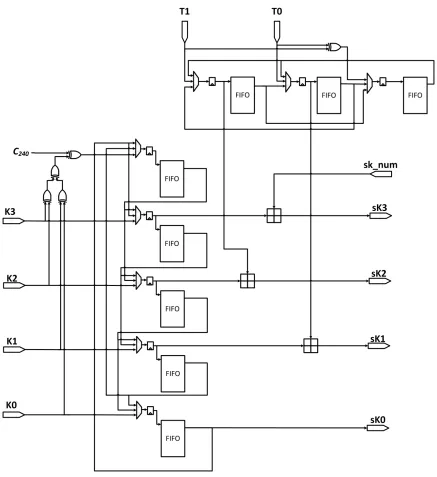
4.1.3
Subkey Generator
The second main component of the Threefish cipher is the subkey generator. As detailed in
the specification section, the subkey generator produces a subkey that is added to the
cur-rent state of Skein before the first round and after every 4th round. In order to accommodate
both the sequential and pipelined Threefish, a specialized subkey generator was developed.
In particular two individual subkey generators are necessary to produce the subkeys for
the unrolled version of Threefish. The pipelined Threefish compression function in this
work contains 10 pipeline registers and thus can hash up to 10 messages simulatenously,
and up to 20 messages for the deep pipelined Threefish core. The subkey generator must
then store the extended key and extended tweak for all 10 messages or 20 messages for
the deep-pipelined architecture. As stated earlier, the highest performing approach to
sub-key generation is to use registers to store the exteded sub-key and extended tweak. For 10
messages, this would require 10·(320 + 192) = 5120 flip flops, which would require a
minimum of 640 slices in a Virtex-6 or 1280 slices in a Virtex-5 as each slice contains 8 or
4 flip-flops respectively for each of the subkey generators [20][19]. Twice the number of
registers would be required for the deep pipelined architecture. Implementing the subkey
generator in this way would be a very area inefficient method to implement the subkey
generator. To save resources, FIFOs are used in place of registers to store the extended key
and extended tweak words. To implement these FIFOs, Xilinx Distributed RAM FIFOs
were used. Distributed RAM utilizes the LUTs as memory, thus reducing resource usage.
There are two main reasons for using distributed RAM. First, the synthesis tools can better
optimize the design and minimize routing delays as the location of the data is not locked
into a particular area of the FPGA. Second, since distributed RAM uses the slice logic,
direct area comparisons can be made to previous work.
Also observing the subkey architecture from [17], unrolling Threefish 8 rounds requires
two subkeys to be generated at the same time for sequential hashing of a single message.
extended key and tweak words by 1 word for pipelined Threefish and by 2 words for
se-quential mode. Descriptions of the inputs and outputs to the subkey generator are shown in
Table 4.1.
Table 4.1: Subkey generator signals for Skein-256
Signal Description
k(255:0) Initial key (chaining value) t(127:0) Initial tweak value
init subkey en Asserted at beginning of new message block to load in key next subkey Asserted to read key and tweak words
from FIFOs and generate next subkey.
Also signifies write shifted words back into FIFO if not last subkey. last subkey Asserted when generating last subkey,
key and tweak works are not written back into FIFOs.
shift two words Tweak and key words are shifted twice when “1” else shifted once.
It is also important to note that in order to improve performance, an additional register
was placed at the input to the FIFO. This register reduces the delay from the output of one
FIFO to the input of another. The extra cycle affects only the generation of the first subkey
adding one cycle to the latency of the pipeline Threefish and no extra cycles to the latency
4.1.4
Tree Hashing with Pipelined Core
The pipelined unrolled core is ideal for hashing multiple messages simultaneouly to
in-crease throughput but there is another advantage to this architecture. Since the pipelined
Threefish compression function can process multiple UBIs concurrently, the tree hashing
mode can be implemented using this same architecture without duplicating the cores. In
[1], multiple sequential cores were utilized to process multiple UBIs for the message at
once. The duplicate cores increase the overall area of the architecture significantly. In
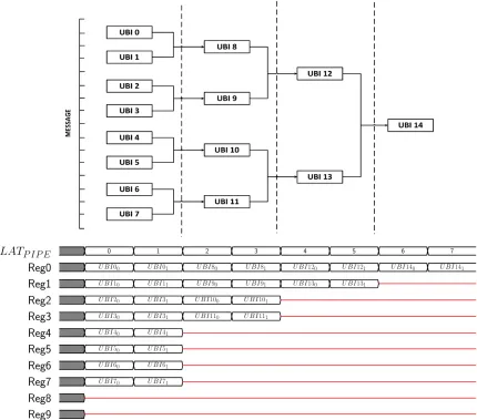
or-der to illustrate how the pipelined architecture can implement tree hashing a few examples
are shown in Figures 4.6, 4.7, 4.8 and 4.8. In the first example shown in 4.6, a message
with 16 blocks and tree parameters of YL = 1 andYF = 1 is hashed in pipeline mode.
In this example all UBIs in the leaf level can be hashed in the latency of two Threefish
blocks orLATP IP E∗2YL = 2∗LATP IP E since the pipelined core is capable of processing
up to 10 independent UBIs simultaneously. The timing diagrams illustrate which UBIs
are processed during a particular Threefish iteration. U BIXi indicates that the Xth UBI
is processing its ith message block. The remaining levels are processed in the same way.
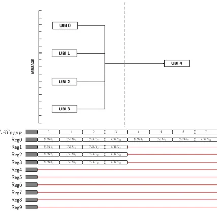
For the same message, the tree parameters are changed to YL = 2and YF = 2 in Figure
4.7. Although the parameters are changed, the total time is not increased since each level
now takes LATP IP E ∗2YL = 4∗LATP IP E cycles but the number of levels was cut in
half. However, in Figure 4.8, YL = 1 and YF = 4, and the total execution time is
in-creased because of the larger tree fanout. For small messages it is apparent that pipelined
tree hashing offers no benefit. However in Figure 4.9, the message size is much large at
4096 blocks. This example shows that all of the pipeline stages are filled much more often
resulting in a significant decrease in processing cycles. Sequentially the message would
take4096·LATSEQ, but with the pipelined tree hashing it only takes464·LATP IP E which
is significantly less time. A detailed analysis of the effect of these parameters on pipeline
tree hashing is presented in the Performance Results and Analysis section. Additionally,
with a pipelined architecture, an entire message block must be delivered to the core every
message block each clock cycle is used in order to achieve the best performance.
Figure 4.9:YL= 4,YF = 4, msgBlocks = 4096
4.1.5
Control
For this architecture to be fully autonomous, a control unit must be developed for the
Three-fish core. The state machine shown in Figure 4.10 is at the heart of the control unit. When
the Skein core receives the coreStart signal indicating that the messages are ready in
mem-ory, the state machine advances from the IDLE state and enters the INIT state. In this state,
the number of blocks, original byte count, and flag indicating the message was padded, for
each of the message(s) is read from memory and stored. The state machine then advances
to one of the three hashing states, SEQ, MULTIPLE MSG, or TREE based on the MODE
input while asserting the ubiStart signal to begin the first UBI. Each of the message(s) is
hashed in this state. If all messages are complete or currently in the last iteration of
Three-fish (Output UBI for sequential and multiple message hashing, or root node message UBI
for tree mode), the state machine advances to the LAST TF state. Once the final Threefish
iteration is complete, the state machine moves to the DONE state, asserts coreDone, and
returns to IDLE.
Additionally in the control unit there are two FIFOs. These FIFOs are used to store the
input message blocks so that they are available at the end of a Threefish operation to XOR
Figure 4.10: Controller state machine
value at the beginning of the next Threefish iteration. A complete block diagram of the
Skein core is shown in Figure 4.11. Table 4.1.5 lists the inputs and outputs to the top level
Table 4.2: Skein core inputs/output
Inputs:
clk, reset wire
coreStart wire Indicates message(s) is/are ready and to start hashing
mode vector(2) Value indicating what mode to operate in (“00” for sequential mode, “01” for multiple message mode, and “11”
for tree hashing mode)
numMessages vector(5) Indicates the number of messages to hash from memory when operating in multiple message mode
msgBlock vector(Nb*8) Message block from memory
Outputs:
msgBlockAddr vector(12) Address to message memory
digestValid vector(pipelineRegs) One-hot vector indicating which messages’ result is ready digestValue vector(Nb*8) Message digest
Chapter 5
Testing Methodology
Due to the complexity of the architecture proposed in this work, multiple testing strategies
were required to verify the architecture. A comprehensive set of behavior and post place
and route simulations were used to model the hardware architecture accurately before
hard-ware verification. The testbenches were designed to resemble the hardhard-ware architecture,
and standardized test vectors were used in both simulations and hardware testing.
5.1
VHDL Simulation
Before testing the design on an FPGA, it had to be fully verified in simulation. The
sim-ulation framework from [1] was modified to accommodate the different modes of hashing
and the new memory storage scheme from this work. Rather than use a simple simulation
variable to store the messages to be hashed, an embedded memory was included in the
testbench in order to act much like the hardware testing framework would. The embedded
memories are dedicated memories on an FPGA designed to store larger amounts of data,
reducing LUT utilization. A memory storage scheme similar to that proposed in [5] was
utilized for both the simulation and hardware verfication of the architectures developed in
this work. Since multiple message hashing is a mode of this hardware architecture, the
em-bedded memory is divided to provide space for multiple messages in a single memory. For
the simulation, the testbench reads the initial chaining value, message bit length, number
from the KAT test vector file. The stimulus file is generated using the JAVA test file
gen-erator from [1]. Using the bit length and number of blocks, the testbench calculates if the
last block was padded or not. If the last block is padded, a “1” is written into the most
significant bit of the first block of a page of memory. Additionally, the number of blocks
(msgBlocks) in the message and total number of message bytes (NM) before padding are
also written to the first block of a page of memory. The message is then written into the
remaining space of memory for that page. Figure 5.1 illustrates the organization of data
in the embedded memory. Since the largest test message used is 134 blocks, the memory
is divided into 256 blocks per page. For the 8-round unrolled and pipelined design, up to
10 messages need to be stored, and thus a 4K deep embedded is needed. For the 8-round
unrolled and deep-piplined architecture, 20 messages must be stored into the memory; an
8K deep embedded is used to accommodate this.
Behavioral simulations tested each mode individually for all 2561 test vectors
gener-ated from the ShortMsgKAT and LongMsgKAT files provided by NIST and the developers
of Skein. Also, simulations were run with dynamic switching between modes as follows: 1
message hashed sequentially, 10 hashed simultaneously, and 1 hashed in tree mode
repeat-ing until all test vectors were completed.
In addtion to the behavioral simulations, post place and route simulations were
exe-cuted. Post place and route simulations are used to simulate the actual propagation delays
in an FPGA. In order for the sequential mode to operate properly, a multicycle path
con-straint is necessary so that synthesis tools are aware that the unpipelined data path registers
are not enabled every clock cycle. All the multiplexers in the Threefish core are connected
to the same control signal, and all select either the registered or unregistered input.
How-ever, the synthesis tools make no assumptions about which input to each multiplexer will
be selected during normal operation. All combinational paths that including those that will
not ever be selected during operation are analyzed bye the synthesizer. To ignore the paths
not used during normal operation, false path constraints must also be added. Due to the
Figure 5.1: Message storage format
capable of processing these constraints in a reasonable amount of time or with a reasonable
amount of memory. The post place and route simulations are used to verify the timing of
the architecture before selecting a clock frequency for the hardware verification. A subset
of test vectors were selected for the post place and route simulations as the execution time
5.2
Hardware Verification
To verify the design in hardware, a testing framework was developed for the Xilinx ML605
development board. This board is based around the Virtex-6 VC6VLT240T-1 FPGA.
Rather than build the hardware testbed from the ground up using VHDL, a soft-processor
was used to provide the Skein core with messages and control signals, as well as to verify
the results from the core. (A soft-processor is a processor that uses the logic on an FPGA
to build a traditional microprocessor.) For this work the Xilinx Microblaze core was used.
Microblaze is a 32-bit reduced instruction set computer (RISC) optimized for Xilinx
FP-GAs [18]. Using the Xilinx Embedded Development Kit (EDK) simplifies the addition of
peripherals, (e.g., I/O, memory, communications, etc). In order to test this design, eight
32-bit wide dual-port BRAMs were added to the Microblaze core to store the messages to
be hashed as well as the results from the Skein core. A simple general purpose input/output
(GPIO) interface was also added to connect the startCore, coreDone, mode, and
numMes-sages signals between Microblaze and the Skein core. Lastly, a Universal Asynchrononus
Receiver Transmitter (UART) peripheral was added to provide a communication link
be-tween the ML605 development board and a PC for debugging and printing the test results.
Figure 5.2: Hardware testing framework
With the Microblaze core constructed, EDK generates the necessary C libraries with
functions that allow access to the processor peripherals. A C program was written to run
the tests similarly to the VHDL testbench. The program first stores the message(s) to be
hashed in the embedded memory, as well as how many blocks each message contains,
whether the message was padded, and how many total bytes were in the original message
before padding. Once this process is complete, Microblaze asserts the correct mode and
numMessages to the core and then asserts startCore. When hashing is complete, the
re-sulting digests are written to the shared embedded memory, and the coreDone signal is
as-serted. Microblaze reads the results from the embedded memory and verifies them against
The basic flow of the hardware testing framework for both the Microblaze processor and
[image:66.612.185.418.137.567.2]the Skein core is shown in Figure 5.3.
5.3
Synthesis and Implementation Automation
In an attempt to synthesize, implement, and test the proposed architectures in this work,
a tool developed at George Mason University was utilized [5]. The Automated Tool for
Hardware EvaluatioN otherwise known as ATHENa is a set of scripts and configuration
files that simplify the process of implementing, optimizing, and verifying the design.
Cur-rently ATHENa supports both Xilinx and Altera FPGAs.
The scripts use the embedded design tools provided by the user (e.g., Xilinx ISE,
Mod-elSim, etc.) for synthesis, implementation, and functional verification (VHDL simulations).
Two main configuration files must be edited by the user to specify how ATHENa will run.
The first file must contain a list of all HDL source files or design files that are required
to synthesize the design. The second configuration file specifies the location of source
files, output directory location for reports and output design files, target devices,
optimiza-tion method, etc. Formulas for the latency and throughput of a particular algorithm can
also be entered in this configuration file, and ATHENa will calculate which design results
in the best throughput, latency, and throughput per area. For this work, multiple target
devices were specified in the configuration file so that ATHENa must run only once for
all target devices, which include Virtex-5 XC5VLX110-3, Virtex-6 XC6VLX240T-1, and
Virtex-6 XC6VLX240T-3. The key advantage to using the ATHENa tool is the
optmiza-tion methods it provides, two of which are focused on. The optimizaoptmiza-tion modes examined
are Frequency Search and GMU Optimization as they are targeted at the frequency
con-straint of the synthesis and implementation tools. Additional optimization algorithms are
provided for reduced area and custom exhaustive search algorithms. The Frequency Search
algorithm is the more primitive of the two algorithms. The user provides a desired frequecy
for each target device in the configuration file. ATHENa then synthesizes and implements
the design and determine if the desired frequency constraint was achieved. If the first
im-plementation achieves this frequency, the frequency constraint for the next iteration will be
increased by a percentage specified in the algorithm. Each time a frequency constraint is
lower percentage. This process is iterated until no frequency improvement is achieved. The
GMU Optimization algorithm is more complicated and modifies many of the parameters of
the tools to achieve better results. The algorithm not only modifies the frequency constraint
but also the effort level of both the mapping and place and route stages. Multiple iterations
with different cost tables are also used. Examples of performance improvements attained
[image:68.612.136.475.232.536.2]for the SHA-3 algorithms through the use of ATHENa are illustrated in Figure 5.4.
Figure 5.4: ATHENa results for SHA-3 candidates [8]
This work experimented with both the Frequency Search and GMU Optimization
op-tions of ATHENa and found that the GMU Optimization method produced the best results
in terms of both maximum clock frequency and overall area for this architecture.
Im-plementations were run for both Virtex-5 and Virtex-6 devices. The results are shown in
architecture (DP). Improvement percentages are measured against implementations with
no optimizations set in the tools.
Table 5.1: Skein-256 - Device : Virtex-5 XC5VLX110-3
Optimization Design Slices CLKSEQ CLKP IP E Number
Method (MHz) (MHz) of runs Frequency Search SP 3278 60.0 260.8 5 GMU Optimization SP 3251 61.1 264.3 62
Frequency Search DP 3847 54.5 282.6 6 GMU Optimization DP 3895 58.3 291.2 65
Table 5.2: Skein-256 - Device : Virtex-6 XC6VLX240T-1
Optimization Design Slices CLKSEQ CLKP IP E Number
Method (MHz) (MHz) of runs Frequency Search SP 2526 48.9 228.3 7 GMU Optimization SP 2547 55.8 246.7 72
Frequency Search DP 3018 49.1 252.4 5 GMU Optimization DP 2972 52.4 269.3 67
Table 5.3: Skein-256 - Device : Virtex-6 XC6VLX240T-3
Optimization Design Slices CLKSEQ CLKP IP E Number
Method (MHz) (MHz) of runs Frequency Search SP 2415 57.8 255.1 6 GMU Optimization SP 2516 71.1 301.9 57
It is important to note that the sequential frequencies were obtained directly from the
post place and route reports, whereas the pipelined frequencies were obtained from reports
generated by the timing analyzer. Timing was also verified in hardware for the
Virtex-6 XCVirtex-6VLX240-1 (MLVirtex-605 Development Board). From these results, it is apparent that
in most cases, ATHENa is able to achieve significant improvements in frequency with
Chapter 6
Performance Results & Analysis
In an effort to compare the architecture designed in this work accurately and fairly to
pre-vious designs, equations must be developed to determine the latency and throughput for
the different modes of hashing supported. The versatile Skein architecture was developed
using many concepts from previous work, and thus some of the metrics used in [1] can be
[image:71.612.110.508.406.650.2]used and/or modified to measure the performance of the versatile Skein architecture.
Table 6.1: Variables for evaluating Skein hardware performance
Variable Description
LATSEQ Number of cycles to process single block of Threefish in sequential mode
LATP IP E Number of cycles to process a single block of
Threefish in multiple message or tree mode
CLKSEQ Maximum clock frequency of sequential data path
CLKP IP E Maximum clock frequency of pipelined data path
msgBlocksi Number of msgBlocks for a given messagei
numM sgs Number of messages to hash in multiple message mode
pipelineRegs Number of pipeline registers (10 for standard pipeline, 20 for deep pipeline)
OHST ART U P Overhead cycles before start of hashing
OHOU T P U T Overhead cycles to complete output UBI of Skein
Nb Number of bytes in a single message block
YL Tree leaf-size encoding
YF Tree fan-out encoding
YM Maximum tree height
U BIL Total number of UBIs at the leaf level in a tree
U BIF Total number of UBIs at all levels except leaf level
LATL Total number of cycles to process leaf level of tree
LATF Total number of cycles to process all levels except leaf level
Before developing the equations to calculate the performance of this architecture for
variable along with some previously defined variables for reference.
6.1
Sequential Hashing
Since the system clock frequency CLKP IP E of the FPGA is used to drive all flip-flops
in the design, when hashing a single message in sequential mode, the internal state
reg-ister is not enabled every clock cycle. Enabling this regreg-ister every CY CLESEN clock
cycles creates a multicycle path. In order to determine CY CLESEN between enabling
the internal state register, the delay of each of the independent paths in the Threefish core
must be considered. From the delay of the sequential (unpipelined) path, the maximum
clock frequency,CLKSEQ, for that path can be determined. Similarly, the maximum clock
frequency for the pipelined path, CLKP IP E, can be determined. Thus the number of
cy-cles between enable pulses when operating in sequential mode is defined by Equation 6.1.
With CY CLESEN defined, the total latency of Threefish in sequential mode, LATSEQ,
is defined by Equation 6.2. Subsequently this latency can be substituted in the throughput
equation for sequential hashing in [1] resulting in Equation 6.3.
CY CLESEN =
CLKP IP E
CLKSEQ
(6.1)
LATSEQ =CY CLESEN ·10 (6.2)
![Figure 2.2: Tweak parameters diagram [14]](https://thumb-us.123doks.com/thumbv2/123dok_us/114311.10903/16.612.117.507.287.549/figure-tweak-parameters-diagram.webp)