Iowa State University Patents
Iowa State University Research Foundation, Inc.
4-11-1995
Magnetostrictive vibration generation system
Alison B. Flatau
Iowa State University
David Hall
Iowa State University
Follow this and additional works at:
http://lib.dr.iastate.edu/patents
Part of the
Aerospace Engineering Commons
This Article is brought to you for free and open access by the Iowa State University Research Foundation, Inc. at Iowa State University Digital Repository. It has been accepted for inclusion in Iowa State University Patents by an authorized administrator of Iowa State University Digital Repository. For more information, please [email protected].
Recommended Citation
Flatau, Alison B. and Hall, David, "Magnetostrictive vibration generation system" (1995).Iowa State University Patents. 92.
Magnetostrictive vibration generation system
Abstract
A shaker with a Terfenol-D rod actuator includes a mass coupled to both ends of the rod through a spring seat,
a spring seat/adjuster and a spring washer. The actuator is mounted inside a cylindrical coil, which in turn is
mounted inside a cylindrical permanent magnet, which in turn is mounted inside a cylindrical housing. An
electrical drive system provides a predetermined excitation signal to the coil to cause the rod to vibrate under
the influence of the magnetic field generated by the coil. One embodiment features a vibrating mass on one
end of the rod. An implantable shaker includes a seal to leak-proof the shaker and a coating of Biomer™. The
implantable shaker can be implanted in an animal to test tissue response to certain vibrations. According to
another embodiment, the Terfenol-D rod actuator is held in place on one end with a pre-stress adjusting
screw, which is threaded into the end of the housing and fixed in place with a jam nut. In all embodiments, a
spring base is seated on one end of the rod actuator and forms an annular coaxial air gap between it and a
spring seat, so that the air gap remains constant when the rod actuator vibrates and the spring base moves
coaxially with respect to the spring seat.
Keywords
Aerospace Engineering
Disciplines
Aerospace Engineering
United States Patent [191
Flatau et a1.
US005406153A
[11]
Patent Number:
[45]
Date of Patent:
5,406,153
Apr. 11, 1995
[54] MAGNETOSTRICI‘IVE VIBRATION
GENERATION SYSTEM
[7 5] Inventors: Alison Flatau; David Hall, both of
~ Ames, Iowa
Iowa State University Research
Foundation, Inc., Ames, Iowa
[21] Appl. No.: 901,534 ~
[73] Assignee:
[22] Filed: Jun. 19, 1992
[51] Int. Cl.6 ... .. H01L 41/12
[52] US. Cl. 310/26
[58] Field of Search ... .. 310/26, 15, 17; 318/118
[56] References Cited
U.S. PATENT DOCUMENTS
4,749,891 6/1988 Sheng ... .. 310/15 5,184,037 2/1993 Kobayashi et a1. ... .. 310/26
OTHER PUBLICATIONS
ABB Seatech AS brochures entitled Low-Frequency
Transducers Based on T erfenol. 4 pages. (undated).
Magespro S.A. brochure entitled Underwater Loud
speaker for Leisure, Sport and ?2r Professionals. 1 page.
(undated).
Sketch of Terfenold-D Vibrator Construction pro
duced by Edge Technologies, Inc., Ames, Iowa, drawn
on Jan. 19, 1994.
Verhoeven, J. D., Gibbons, E. D., and McMasters, O.
D., “The Growth of Single Crystal Terfenol-D Crys
tals,” Metals Transactions, vol. 18A, p. 223, 1987 monthunknown.
Verhoeven, J. D., Gibbons, E. D., McMasters, O. D.,
and Ostenson, J. E., “Directional solidi?cation and Heat Treatment of Terfenol-D Magnetorestrictive Ma
terials,” Metals Transaction, vol. 21A, p. 2249, 1990
month unknown.
Jiles, D. C., “Development and Characterization of
Terfenol-D for Use in Sensors and Actuators,” New
Materials and Their Applications, edited by D. Holland,
Institute of Physics, London, p. 365, 1990 month un known.
Hiller, M. W., Bryant, M. D., and Umegaki, J., “Attenu
ation and Transformation of Vibration Through Active
Control of Magnetostrictive Terfenol,” Journal of
Sound and Vibration, vol. 134, No. 3, pp. 507-519, 1989month unknown.
Miller, C. 6., “High Force, High Strain, Wide Band
XVII/JIM g
W
////////l.
m
__,
width Linear Actuators Using the Magnetostrictive
Material Terfenol-D”, Proceedings on the Conference on Recent Advances in Active Control of Sound and Vibra
tion, Technomic Publishing Co., Inc., Lancaster, Pa.,
1991 month unknown.
Harris, C. M., Shock and Vibration Handbook, third edition, pp. 25-1 to 25-26, McGraw-Hill, New York,
N.Y., 1988 month unknown.
Butler, J. L., “Application Manual for the Design of
Etrema Terfenol-D Magnetostrictive Transducers,”
Etrema Division, Edge Technologies, Inc., 1988 monthunknown.
“Terfenol-D Notes”, vol. 4, No. 1, p. 4, Edge Technol ogies, Jan. 1991.
“Magnetostrictive Actuators”, Edge Technologies,
Etrema Products Division date unknown.
Primary Examiner-Steven L. Stephan
Assistant Examiner—Judson H. Jones
Attorney, Agent, or Firm-Schwegman, Lundberg &
Woessner
[51]
ABSTRACT
A shaker with a Terfenol-D rod actuator includes a mass coupled to both ends of the rod through a spring seat, a spring seat/adjuster and a spring washer. The actuator is mounted inside a cylindrical coil, which in turn is mounted inside a cylindrical permanent magnet, which in turn is mounted inside a cylindrical housing. An electrical drive system provides a predetermined excitation signal to the coil to cause the rod to vibrate
under the in?uence of the magnetic ?eld generated by
the coil. One embodiment features a vibrating mass on one end of the rod. An implantable shaker includes a seal to leak-proof the shaker and a coating of Bi omer'nvi. The implantable shaker can be implanted in an animal to test tissue response to certain vibrations.
According to another embodiment, the Terfenol-D rod
actuator is held in place on one end with a pre-stress adjusting screw, which is threaded into the end of the housing and ?xed in place with a jam nut. In all embodi ments, a spring base is seated on one end of the rod actuator and forms an annular coaxial air gap between it and a spring seat, so that the air gap remains constant when the rod actuator vibrates and the spring base moves coaxially with respect to the spring seat.
27 Claims, 21 Drawing Sheets
IO
US. Patent
Apr. 11, 1995
Sheet 1 0f 21
5,406,153
FIG. 3 i
US. Patent
Apr. 11, 1995
Sheet 2 of 21 _
5,406,153
On
l
1:73.14‘
g?
, If?
m
_u\\\\\\\\\\\\
US. Patent
Apr. 11, 1995
Sheet 6 of 21
5,406,153
FIG. I3
34
:
33
/26
-._-...L
i-rlllll HIIIH
_ ~~22
US. Patent
Apll'. 11, 1995
Sheet 8 of 21
5,406,153
US. Patent
Apr. 11, 1995 '
Sheet 9 of 21
5,406,153
FIG. I8
5s
5!
59
30
US. Patent
Apr. 11, 1995
Sheet 10 of 21
5,406,153
dB EU 0dB=1
/dB
‘lK/DIV
O 0
10
/ DN
'
-80 . . . .
O --- HER'IZ -— 10K
Ch=2l ASPECa
v/ g= 0.0401
A xnucaz /
f: 5.75KHZ
y: -—10.79dB
RMS: 3.849489
FIG. 19A
dBEUOdB=
1
/dB
1K/DN
V=BU(.
2O
|=GRAY
1O
/ DIV
—8O . I . . . . r . .
0 —- HERTZ —— 10K
Ch=3/ASPECOV/VOLT=1
VXDUCIN/
INP
=1/
0 V/ AMP = 0.4-6
IXDUCER /
f: OHz
y: -35.28dB
RMS: 2.55711VOLT
dy: 15.88
y: —51.17dB
RMS: 54.299mAMP
US. Patent
Apr. 11, 1995
Sheet 11 0f 21
5,406,153
VOLT / AMP
/ UN
2K / DIV
IMPEDANCE
360 _ 50 ‘
/ DIV I
O_ —— HERTZ —— 20K
Ch=3/1XFER mV/VOLT=1 VXDUClN/IXDUCER
f: 15.1KHz
y: 319.5VOLT / AMP
FIG. 20A
VOLTS
/ UN
2K / DN
COHERENCE
1
100m
/ DIV
O -— HERTZ —— 20K
Ch=3/1 00H
\IXDUClN/IXDUCER
f: 25Hz
y: 998m
US. Patent
Apr. 11, 1995
Sheet 12 0f 21 ‘
5,406,153
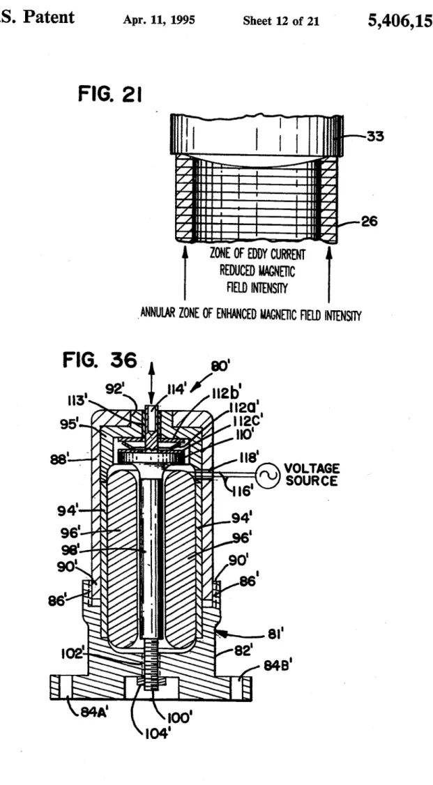
FIG. 2| _
I
33
26
REDUCED NAGNETTC
FIELD INTENSITY
ANNULAR ZONE 0F ENHANCED NACNETIC FIELD TNTENSITY
I ZONE 0F EDDY CURRENT
FIG.
T I
a)‘
92' I
"iv/ugh‘
‘ I
I
95
“x
.
|
/ .
'- ' VOLTAGE
/
"U SOURCE
/ '5' ,
94‘ /
|
94'
962-?‘ a '
9e."
\
90'
\T‘
86'
86l
. a1‘
' . ' 82'
I02
'
848.
E - §~
\84A' k \loo'
US. Patent
Apr. 11, 1995
Sheet 13 of 21
5,406,153
NN
.0: ,
~: .1.
.6538“...
025M
coon
P
coco
_.
coon
o
mm¥<Im I
I: KN imam-t.
WEI-m Ill
__ N
US. Patent
Apr. 11, 1995
Sheet 14 of 21
5,406,153 -
dBEUOdB=1; /dB
20
180
PHASE
6
2G1
MAGNITUDE
|.'..
8%
l IIIIIIII I IIIIIIIw100 —— HERTZ --- 10K
Ch=2l3 XFER b V/ g=0.0407 AXDUCER/V XDUCIN
f: 3.4-6875KH2
y: 6.53MB
y: —6.061 DEGREES
FIG. 23A
VOLTS
/ UN
1 /a_/—
100m:
/D|V -
o I I I I I I I I] I 1 l I I I I 1
100 -- HER'IZ -— IOK
Ch=2/ 3 00H
A XDUCER /V XDUC IN
f: 118.75Hz
y: 922.3m
US. Patent
Apr. 11, 1995
Sheet 16 of 21
5,406,153
'
FIG. 26
so‘
i'
i
< _
M
II
: —
|
\ I
i
62 \ _
626°
—
6'
L34‘
US. Patent
Apr. 11, 1995
Sheet 17 of 21
5,406,153
dB EU 0dB=
2.457002 / dB
Sl-IAKER=BLACK um; VENTRICLE=GRAY um:
x I | IIIIII T l 1 III]
100
--HER1Z-—>
10K
Ch=2/ASPEC0 v/ g=o.o4o7 AXDUCER/V
FILECh=2l
'
c
v/
9=0.0407 AXDUCER/
f: 262.5Hz
y: -15.6dB
RMS: 2.347589
dy: -4-.155
y: -11.44dB
RMS: 2.248139
FIG. 31A
9
UN
10m / DN
SHAKER
24-.57_
5:
/DIV :
_24'.57- I l I l I I I I
—31.99m —— SECONDS —— 47.97m
Ch=2l TIMEi V/
g=0.407
A XDUCER/
t: 3.7890641m8 y: 12.019
US. Patent
Apr. 11, 1995
Sheet 18 of 21
5,406,153
dB EU 0dB=
2.457002 / dB
SHAKER=BLACK UNE VENTRICLE=GRAY UNE
10
/DIV—
I I I Illlll I I I IIIII
100 —- HERTZ —— 10K
Ch=7J ASPECG
V/ q= 0.0407
A XDUCER
FILE Ch=2l
a V/ g= 0.0407
A XDUCER
f: 262.5Hz
y: —15.9dB
RMS: 2.630159
dy: -4.155
y: -11.44dB
RMS: 2.248139
FIG. 32A
9
\
UN
10m / DIV
SHAKER
24-.57q
5 I
/DIV '
l I I I | I I 1
-31.99m —- SECONDS --— 4-7.97m
Ch=2l TlHEi V/
g=0.407
A XDUCER/
u s,1s4os41ms_ y: 12.449